


TD500/TD300
هﺮﮐ ﮓﻧﺎﯿﻧﺎﻫ تﻻﻮﺼﺤﻣ یرﺎﺼﺤﻧا هﺪﻨﯾﺎ ناﻮﯿﺳ ﺖﮐﴍ
021-33989001
www.sivancarno.com
021-33989002
2 Channel Programmable Temperature Controller
MANUAL

Notice
هﺮﮐ ﮓﻧﺎﯿﻧﺎﻫ تﻻﻮﺼﺤﻣ یرﺎﺼﺤﻧا هﺪﻨﯾﺎ ناﻮﯿﺳ ﺖﮐﴍ
021-33989001
www.sivancarno.com
021-33989002
This user guide is protected by copyright and has all the rights related to it. Without prior authorization
from HANYOUNG, this guide and any parts contained in this guide cannot be reproduced, copied, or
translated in another language.
Contents of this guide will be provided in this form and can be edited or changed without prior
noticed.
This guide includes implied guarantee or suitability for a certain purpose, and it does not offer any
guarantee for those that do not limit this matter.
Every programs contained in this product is protected by copyright. Without prior authorization from
HANYOUNG, this product and any parts contained in this product cannot be reproduced, copied, or
translated in another language.
Every title, symbols, figures, service marks, and etc in this guide or the product are legally registered.
HANYOUNG NUX
28, Gilpa-ro 71beon-gil, Nam-gu, Incheon, Korea
TEL : (82-32)876-4697
FAX : (82-32)876-4696
http://www.hynux.net
E-mail. overseas@hynux.com
3

CONTENTS
هﺮﮐ ﮓﻧﺎﯿﻧﺎﻫ تﻻﻮﺼﺤﻣ یرﺎﺼﺤﻧا هﺪﻨﯾﺎ ناﻮﯿﺳ ﺖﮐﴍ
021-33989001
www.sivancarno.com
021-33989002
1 Before starting
2 Installation instruction
3 Setting and operation
4 Display
5 Function setting
1.1 Checking Product
1.2 Safety Information
2.1 Installation place and caution notice
2.2 Installation method
2.3 Suffix code
2.4 Dimensions / Panel cutout and terminal arrangement
2.5 Terminal arrangement method
3.1 Initial screen
3.2 Basic input mehtod
3.3 Name of operation screen
3.4 Fixed control operation
3.5 Program control operation
3.6 Graph indication and setup
3.7 Errors and indicators for various events
4.1 Operation screen
4.2 Setup screen
5.1 Operation setup
5.2 Time/Timer setup
5.3 Program setup
5
6
7
8
9
9
11
15
15
17
26
27
30
31
32
34
35
36
36
6 System setting
7 Specification
6.1 Sensor input setup
6.2 Control/Transmission setup
6.3 Inner signal setup
6.4 Alarm setup
6.5 PID setup
6.6 Inputs at point of contect (DI) setup
6.7 Point of contact output (DO) setup
6.8 Communication setup
6.9 Other setup
7.1 Input sepcification
7.2 Output specification
7.3 Functions
7.4 Communication
7.5 Ratings
7.6 Operation environment
7.7 Condition of transport and storage
40
41
42
43
43
45
46
48
48
49
49
50
51
51
52
52
4

1 Before starting
هﺮﮐ ﮓﻧﺎﯿﻧﺎﻫ تﻻﻮﺼﺤﻣ یرﺎﺼﺤﻧا هﺪﻨﯾﺎ ناﻮﯿﺳ ﺖﮐﴍ
021-33989001
www.sivancarno.com
021-33989002
Thank you for the purchase of HANYOUNG 2 Loop Temperature Controller (Model : TD500).
This manual contains the function of product, install method, caution information and the way of using
this controller. So please read this manual before using it. And also please make this manual to be
delivered to the final user and to be placed where can be found and seen easily
Contents of this user manual can be edited without prior notice for improvement and modification of the
product
1.1 Checking product
After purchasing our product, please check if it is correct item you want. Also please check breakage
on exterior and omission parts.
If it is a different controller which you want or you find omission parts, please contact our sales office.
1.1.1 TD500
Unit body
1.1.2 TD300
I/O Board 1
Resistance 250Ω × 2
Fixing bracket
40p cable
Manual
Unit body
Fixing bracket
Manual
5

1.2 Safety information
هﺮﮐ ﮓﻧﺎﯿﻧﺎﻫ تﻻﻮﺼﺤﻣ یرﺎﺼﺤﻧا هﺪﻨﯾﺎ ناﻮﯿﺳ ﺖﮐﴍ
021-33989001
www.sivancarno.com
021-33989002
1.2.1. Safety notice
●
For safety and security of the system that is connected to the product, please read and follow this
manual carefully.
●
We are not responsible for any damages and safety problems due to disregards of the manual or
lack of care of the product.
●
Please install any extra safety circuitry or other safety materials outside the product for safety of
the program that is connected to the product.
●
Do not disassemble, repair or reconstruct the product. It can cause electric shock, fire, and errors.
●
Do not give impact to products. It can cause of damage or malfunction.
1.2.2 Quality guarantee
●
Unless it is included company's conditions for warrantee, we are not responsible for any
warranties or guarantees.
●
We are not responsible for any damages and indirect loss of the use or third person due to
unpredicted natural disasters.
1.2.3 Quality guarantee conditions of product
●
The warranty for this product is valid for 1 year from purchase, and we will fix any breakdowns
and faults from proper uses as it is mentioned in this manual for free.
●
After the warranty period, repair will be charged according to our standard policies.
●
Under following conditions, repair will be charged even during warranty period.
•
Breakdowns due to user's misuses
•
Breakdowns due to natural disasters
•
Breakdowns due to moving the product after installation
•
Breakdowns due to modification of the product
•
Breakdowns due to power troubles
●
Please call our customer service for A/S due to breakdowns.
6

2 Installation method
هﺮﮐ ﮓﻧﺎﯿﻧﺎﻫ تﻻﻮﺼﺤﻣ یرﺎﺼﺤﻧا هﺪﻨﯾﺎ ناﻮﯿﺳ ﺖﮐﴍ
021-33989001
www.sivancarno.com
021-33989002
This is information for installation place and method of TD500 (2 loop temperature controller). So please
ready it before installation.
2.1 Installation place and caution notice
2.1.1 Installation place
●
To avoid electric shock, please use it after installation to panel
●
Please avoid installing the product for following places where
•
People can touch terminal unconsciously
•
Directly exposed to the mechanical vibration or impact
•
Exposed to the corrosive gas or combustible gas
• It is exposed to mechanical shock or vibration
• Danger of corrosion or combustion of gas exist
• Temperature changes too frequently
• Temperature is either too high or too low
• It is exposed to direct rays
• It is exposed to electromagnetic waves too much
• Humid place
• It has many combustible objects
• It has dusts and salinity
2.1.2 Caution
●
The case of this controller is chrome-zinc plating and Bezel is made by ABS/PC anti-combustion
material but please not install it to the inflammable place. Especially please do not put it on the
inflammable products.
●
Please keep it away from the machine or wires that can be cause of noise.
Especially, please have enough warn-up when you operate it under 10 ℃ temperature.
●
Please install it on horizontally
●
When you wire it, please cut out all of electric power.
●
This controller is operating in 100 - 240 V AC, 50-60 Hz without additional change.
If you use other voltage, it may case of fire and electric shock.
●
Do not operate controller with wet hand, it may cause of electric shock.
●
Please follow Safety Information to prevent any fire, electric shock and any damage.
●
Please follow this manual for install and operation of this controller.
●
When you put to earth, please refer to install method. But do not it earth to gas pipes, phone lines
and lightning rods
●
Please do not turn on power until you install all of parts
●
Please do not block ventilating windows. It may cause of break down.
●
The grade of over voltage is CatalogueⅡ and using environment is DegreeⅡ
7

2.2 Installation method
هﺮﮐ ﮓﻧﺎﯿﻧﺎﻫ تﻻﻮﺼﺤﻣ یرﺎﺼﺤﻧا هﺪﻨﯾﺎ ناﻮﯿﺳ ﺖﮐﴍ
021-33989001
www.sivancarno.com
021-33989002
(1) Please use 1 mm ~ 10 mm thickness of a steel sheet for panel.
(2) In front of panel, please push into TD500 temperature controller
(3) Using fixing bracket, please adhere controller to the panel
(4) If you tighten it up by fixing iron to panel, it can be cause break of case or fixing bracket.
Caution
●
To prevent electric shock, please check 'turn off power'
●
Before turn on power, please connect over the third
class grounding.
●
During retransmission, it may cause electric shock so
please do not touch terminal.
●
Please wire it after turn off main power
●
Please contact around 2A fuse to main electronic power line.
8

2.3 Suffix Code
هﺮﮐ ﮓﻧﺎﯿﻧﺎﻫ تﻻﻮﺼﺤﻣ یرﺎﺼﺤﻧا هﺪﻨﯾﺎ ناﻮﯿﺳ ﺖﮐﴍ
021-33989001
www.sivancarno.com
021-33989002
MODEL CODE DESCRIPTION
TD500 2 LOOP PROGRAMMABLE TEMPERATURE CONTROLLER
N NONE
BODY
(SEPARA TYPE)
1 SEPARATE BODY(RS422/485 + USB)
2 SEPARATE BODY(RS232C + USB)
BODY(UNIT)
I/O BOARD
3 UNIT BODY(RS422/485 + USB), I/O TERMINAL BUILT-IN
4 UNIT BODY(RS232C + USB), I/O TERMINAL BUILT-IN
N NO I/O BOARD
1 SEPARATE TYPE I/O BOARD
2.4 Dimensions / Panel cutout and Terminal arrangement
2.4.1. TD500 Unit body
[unit : mm]
9

2.4.2 TD500 I/O board
هﺮﮐ ﮓﻧﺎﯿﻧﺎﻫ تﻻﻮﺼﺤﻣ یرﺎﺼﺤﻧا هﺪﻨﯾﺎ ناﻮﯿﺳ ﺖﮐﴍ
021-33989001
www.sivancarno.com
021-33989002
2.4.3. TD500 Body terminal arrangement
[unit : mm]
2.4.3. TD500 I/O Board terminal arrangement
10

2.5 Terminal arrangement method
هﺮﮐ ﮓﻧﺎﯿﻧﺎﻫ تﻻﻮﺼﺤﻣ یرﺎﺼﺤﻧا هﺪﻨﯾﺎ ناﻮﯿﺳ ﺖﮐﴍ
021-33989001
www.sivancarno.com
021-33989002
2.5.1 Power
● Grounding needs over 2 mm 2 wire and at least the third
class grounding connection (Grounding resistance below
100Ω). Grounding cable should be within 20 meters.
2.5.2 Sensor Input
Caution
• Please use input wire with shield. And the shield needs to have
1 point grounding.
• Please leave a space for Sensor line against power line or
grounding line.
11

2.5.3 Control output and retransmission arrangement
هﺮﮐ ﮓﻧﺎﯿﻧﺎﻫ تﻻﻮﺼﺤﻣ یرﺎﺼﺤﻧا هﺪﻨﯾﺎ ناﻮﯿﺳ ﺖﮐﴍ
021-33989001
www.sivancarno.com
021-33989002
Caution
•
Please pay attention about output polarity when you wire
•
Please use shield line for output line. And shield needs
1 point ground.
2.5.4 Relay out
12
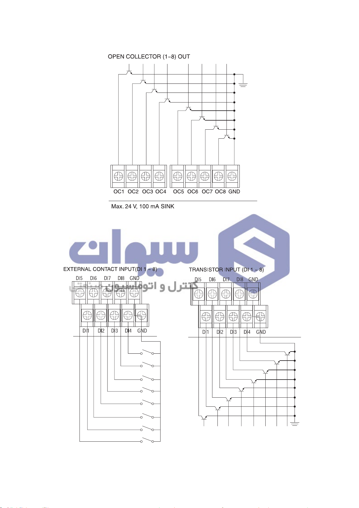
2.5.5 Transistor (O/C) output
هﺮﮐ ﮓﻧﺎﯿﻧﺎﻫ تﻻﻮﺼﺤﻣ یرﺎﺼﺤﻧا هﺪﻨﯾﺎ ناﻮﯿﺳ ﺖﮐﴍ
021-33989001
www.sivancarno.com
021-33989002
2.5.6 Contact input
13

2.5.7 Communication arrangement
هﺮﮐ ﮓﻧﺎﯿﻧﺎﻫ تﻻﻮﺼﺤﻣ یرﺎﺼﺤﻧا هﺪﻨﯾﺎ ناﻮﯿﺳ ﺖﮐﴍ
021-33989001
www.sivancarno.com
021-33989002
•RS422/RS485 arrangement
TD500 can contact maximum 256 machines.
Please contact Terminating Resistance (100 ~ 200 Ω 1/2 W) to the both of ends for
communication lines.
RS485 Connection (2 Wires)
RS422 Connection (4 Wires)
•RS232 arrangement
14

3 Setting and Operation
هﺮﮐ ﮓﻧﺎﯿﻧﺎﻫ تﻻﻮﺼﺤﻣ یرﺎﺼﺤﻧا هﺪﻨﯾﺎ ناﻮﯿﺳ ﺖﮐﴍ
021-33989001
www.sivancarno.com
021-33989002
3.1 Initial screen
When the power is turned on after installation, the logo screen is indicated for 3 seconds, after
which the first operation screen is shown. (Logo screen can be changed by the user through
communication functionality.)
3.2 Basic input method
[Table 1]
Category of Buttons Name Function
Selection
Button
Activation Input
Box
Deactivation
Input Box
Button selected by the need of the users. When pressed,
the button is reversed, and the corresponding operation is
selected while the button is being released.
Window to set various settings needed by the users. When
pressed, the corresponding range of numbers or characters
input window appears, and the needed value is to be pressed.
Although it’s an input window, depending on the current
condition or status, this window is deactivated. When the
condition is met, it is converted to an activated input window.
15

3.2.1 Numerical Input Window
هﺮﮐ ﮓﻧﺎﯿﻧﺎﻫ تﻻﻮﺼﺤﻣ یرﺎﺼﺤﻧا هﺪﻨﯾﺎ ناﻮﯿﺳ ﺖﮐﴍ
021-33989001
www.sivancarno.com
021-33989002
Positive and real numbers can be inputted at the
basic number input window. On the top left, the
`input area'and 'max/min value' are indicated,
and the current input value is indicated on the
number board's indication box. The input number is
inputted when the button is pressed, and if
is pressed beforehand, the current input is
cancelled.
3.2.2 Character Input Window (Korean/English/Numeric Character)
Character input is possible. It is shown when setting the pattern name, contact input (DI) name and
etc. Korean/English/Numeric Character conversion is possible by using the keyboard conversion
button.
16

3.3 Name of operation screen
هﺮﮐ ﮓﻧﺎﯿﻧﺎﻫ تﻻﻮﺼﺤﻣ یرﺎﺼﺤﻧا هﺪﻨﯾﺎ ناﻮﯿﺳ ﺖﮐﴍ
021-33989001
www.sivancarno.com
021-33989002
① ② ③
④
⑦
⑩
⑫ ⑬⑭ ⑯
(1st Screen for Fixed Control Operation, 2 channel simultaneous operation mode)
No. Name No. Name
⑪
⑤
⑥
⑧
⑨
⑮
⑰
①
Current screen information
②
Menu button for function setting
③
Conversion button to next screen
④
CH.1 Process Value(PV) display
⑤
CH.1 Target Set Value(TSV) input box
⑥
CH.1 Current target set value display
⑦
CH.2 Process Value(PV) display
⑧
CH.2 Target Set Value(TSV) input box
⑨
CH.2 Current target set value display
⑩
CH.1 PID zone input box
⑪
CH.2 PID zone input box
⑫
CH.1 A.T button
⑬
CH.2 A.T button
⑭
Current Date / Time display
⑮
Operation progress time
⑯
Operation Start button
⑰
Operation Stop button
17

(1st Screen for Fixed Control Operation, 2 channel separate operation mode)
هﺮﮐ ﮓﻧﺎﯿﻧﺎﻫ تﻻﻮﺼﺤﻣ یرﺎﺼﺤﻧا هﺪﻨﯾﺎ ناﻮﯿﺳ ﺖﮐﴍ
021-33989001
www.sivancarno.com
021-33989002
(1st Screen for Fixed Control Operation, 1 channel operation mode)
18

① ② ③
هﺮﮐ ﮓﻧﺎﯿﻧﺎﻫ تﻻﻮﺼﺤﻣ یرﺎﺼﺤﻧا هﺪﻨﯾﺎ ناﻮﯿﺳ ﺖﮐﴍ
021-33989001
www.sivancarno.com
021-33989002
④
⑧
⑫
⑬
⑱ ⑳
(1st Screen for Program Operation, 2 channel separate operation mode)
No. Name No. Name
⑮⑭ ⑯
⑰
⑤
⑥
⑦
⑨
⑩
⑪
⑲
①
Current screen information
②
Menu button for function setting
Conversion button to next screen
③
(Move to 2nd operation screen)
④
CH.1 Process Value(PV) display
⑤
CH.1 Operation Pattern input box
CH.1 Operation Pattern Segment information
⑥
(Current segment number / Total segment
number of pattern)
⑦
CH.1 Current target set value display
⑧
CH.2 Process Value(PV) display
⑨
CH.2 Operation Pattern input box
CH.1 Operation Pattern Segment information
⑩
(Current segment number / Total segment
number of pattern)
⑪
CH.2 Current target set value display
⑫
CH.1 Operation pattern name
⑬
CH.2 Operation pattern name
⑭
CH.1 Step button
⑮
CH.1 Hold button
⑯
CH.2 Step button
⑰
CH.2 Hold button
⑱
Current Date / Time display
⑲
Operation progress time
⑳
CH.1, CH.2 Operation button
19

(1st Screen for Program Operation, 2 channel simultaneous operation mode)
هﺮﮐ ﮓﻧﺎﯿﻧﺎﻫ تﻻﻮﺼﺤﻣ یرﺎﺼﺤﻧا هﺪﻨﯾﺎ ناﻮﯿﺳ ﺖﮐﴍ
021-33989001
www.sivancarno.com
021-33989002
(1st Screen for Program Operation, 1 channel operation mode)
20

⑤
هﺮﮐ ﮓﻧﺎﯿﻧﺎﻫ تﻻﻮﺼﺤﻣ یرﺎﺼﺤﻧا هﺪﻨﯾﺎ ناﻮﯿﺳ ﺖﮐﴍ
021-33989001
www.sivancarno.com
021-33989002
①
② ③④
⑧
⑨
⑦
⑥
⑫
⑬
⑭
⑮
⑰
(2nd Screen for Fixed Control Operation, 2 channel simultaneous operation mode)
No. Name No. Name
①
Current screen information
②
Menu button for function setting
Conversion button to next screen
③
(Move to 3rd operation screen)
CH.2 Current target set value display and
⑪
Control output value (H.MV, C.MV)
⑫
Time signal status display
⑬
Inner signal status display
⑲⑱⑯
⑪
⑩
④
CH.1 P. I. D zone display
⑤
CH.1 Process Value(PV) display
⑥
CH.1 Target Set Value(TSV) input box
CH.1 Current target set value display and
⑦
Control output value (H.MV,C.MV)
⑧
CH.2 P. I. D zone display
⑨
CH.2 Process Value(PV) display
⑩
CH.2 Target Set Value(TSV) input box
⑭
Contact input status display
⑮
Alarm status display
⑯
Error status display / Confirmation button
⑰
Operation progress time display
⑱
Operation Start button
⑲
Operation Stop button
21

(2nd Screen for Fixed Control Operation, 2 channel separate operation mode)
هﺮﮐ ﮓﻧﺎﯿﻧﺎﻫ تﻻﻮﺼﺤﻣ یرﺎﺼﺤﻧا هﺪﻨﯾﺎ ناﻮﯿﺳ ﺖﮐﴍ
021-33989001
www.sivancarno.com
021-33989002
(2nd Screen for Fixed Control Operation, 1 channel operation mode)
22

⑤
هﺮﮐ ﮓﻧﺎﯿﻧﺎﻫ تﻻﻮﺼﺤﻣ یرﺎﺼﺤﻧا هﺪﻨﯾﺎ ناﻮﯿﺳ ﺖﮐﴍ
021-33989001
www.sivancarno.com
021-33989002
①
② ③④
⑧
⑨
⑦
⑥
⑫
⑬
⑭
⑮
⑰
(2nd Screen for Program Operation, 2 channel simultaneous operation mode)
No. Name No. Name
①
Current screen information
②
Menu button for function setting
Conversion button to next screen
③
(Move to 3rd operation screen)
⑯
⑩
CH.2 Target Set Value(TSV) display
CH.2 Current target set value display and
⑪
Control output value (H.MV, C.MV)
⑫
Time signal status display
⑪
⑩
⑱
④
CH.1 P. I. D zone display
⑤
CH.1 Process Value(PV) display
⑥
CH.1 Target Set Value(TSV) display
CH.1 Current target set value display and
⑦
Control output value (H.MV, C.MV)
⑧
CH.2 P. I. D zone display
⑨
CH.2 Process Value(PV) display
⑬
Inner signal status display
⑭
Contact input status display
⑮
Alarm status display
⑯
Error status display / Confirmation button
⑰
Operation progress time display
Program operation status display for each
⑱
channel
23

(2nd Screen for Program Operation, 2 channel separate operation mode)
هﺮﮐ ﮓﻧﺎﯿﻧﺎﻫ تﻻﻮﺼﺤﻣ یرﺎﺼﺤﻧا هﺪﻨﯾﺎ ناﻮﯿﺳ ﺖﮐﴍ
021-33989001
www.sivancarno.com
021-33989002
(2nd Screen for Program Operation, 1 channel operation mode)
24

① ② ③
هﺮﮐ ﮓﻧﺎﯿﻧﺎﻫ تﻻﻮﺼﺤﻣ یرﺎﺼﺤﻧا هﺪﻨﯾﺎ ناﻮﯿﺳ ﺖﮐﴍ
021-33989001
www.sivancarno.com
021-33989002
⑨
④
⑤
⑬
(3rd Screen for Program Operation, 2 channels operation mode)
No. Name No. Name
①
Current screen information
②
Menu button for function setting
Conversion button to next screen
③
(Move to 1st operation screen)
⑪
⑫
⑩
⑭
⑨
Hidden button for lifting screen
⑩
Hidden button for descending screen
⑪
Hidden button for magnifying screen
⑥
⑦
⑧
⑮
④
CH.1 Process Value(PV) display
⑤
CH.1 Target Set Value(TSV) display
⑥
CH.2 Process Value(PV) display
⑦
CH.2 Target Set Value(TSV) display
⑧
Channel selection button
⑫
Hidden button for reducing screen
⑬
Hidden button for descending screen
⑭
Hidden button for increasing time axis
⑮
Button for moving to graph setting menu
25

(3rd Screen for Program Operation, 1 channels operation mode)
هﺮﮐ ﮓﻧﺎﯿﻧﺎﻫ تﻻﻮﺼﺤﻣ یرﺎﺼﺤﻧا هﺪﻨﯾﺎ ناﻮﯿﺳ ﺖﮐﴍ
021-33989001
www.sivancarno.com
021-33989002
3.4 Fixed Control Operation
Fixed Control Operation controls the temperature at certain set value (SV).
3.4.1 Select Fixed Control Operation
- Start Operation : After inputting the set value (SV) for each channel at Fixed Control
Operation Screen, when [RUN] is pressed, the operation commences after verification.
LED light flashes to indicate that it's in operation at this time. (At the operation mode
of each channel, the RUN button is in toggle form).
- Stop Operation : When [STOP] button is pressed during operation, the operation stops
after verification.
(1st Fixed Control Operation Screen)
26

When selecting the Fixed Control or the program, pressing the [MENU] button (in stop mode) displays
هﺮﮐ ﮓﻧﺎﯿﻧﺎﻫ تﻻﻮﺼﺤﻣ یرﺎﺼﺤﻧا هﺪﻨﯾﺎ ناﻮﯿﺳ ﺖﮐﴍ
021-33989001
www.sivancarno.com
021-33989002
the screen for function setup menu.
Press [RUN SETTIN] button on this screen to move to RUN SETUP1 screen, then make selection in
RUN METHOD.
During fixed control operation, if the set value (SV) is altered, the applied PID GAIN is automatically
adjusted according to the set value. At automatic selection setting, if a certain PID GAIN value needs
to be used, after setting the PID ZONE selection to manual, input the PID ZONE numbers directly.
(When setting up this product for the first time, the PID GAIN must be set for each zone, and in order
to do this, the auto tuning procedure must be performed. At this time, the PID menu must be set, for
A/T button to appear on the screen. Also, the auto tuning is possible only at fixed control operation
mode. When auto tuning is finished for each zone, it is advisable to make adjustment, so A/T button
is not displayed on the operation screen).
3.4.2 screen 2 for Fixed Control Operation
The status for each signal is shown on screen 2 of fixed control operation.
3.5 Program Control Operation
The program control operation is the operation that changes the intended value (SV) with time and
achieving the wanted pattern of operation. The user pre-programs the wanted operation pattern, and
when running, the pattern number is selected, and starts to run at program mode.
27

3.5.1 Select Program Control Operation
هﺮﮐ ﮓﻧﺎﯿﻧﺎﻫ تﻻﻮﺼﺤﻣ یرﺎﺼﺤﻧا هﺪﻨﯾﺎ ناﻮﯿﺳ ﺖﮐﴍ
021-33989001
www.sivancarno.com
021-33989002
In order to run on program control, press [MENU] on the operation screen (while stopped) to enter
the MENU screen. Then press [RUN MODE] to enter the operation selection screen, and select the
operation to [PROGRAM].
3.5.2 Program Setup
28

(When setting operation mode or 1 channel usage mode for each channel)
هﺮﮐ ﮓﻧﺎﯿﻧﺎﻫ تﻻﻮﺼﺤﻣ یرﺎﺼﺤﻧا هﺪﻨﯾﺎ ناﻮﯿﺳ ﺖﮐﴍ
021-33989001
www.sivancarno.com
021-33989002
(When setting simultaneous operation mode for each channel)
Press [PATTERN SETUP] button at program setup menu to move to program pattern setup screen.
Pattern consists of 'segments'. With each segment, various specific settings are carried out. The
maximum number of segments for each pattern is limited to 100, and the maximum number of loops
contained in one pattern is limited to 20. (These limits can be extended by pattern repeats and
repeated operation).
29

The start of the operation in program mode starts from the PV at the time of the start (when PV2 is
هﺮﮐ ﮓﻧﺎﯿﻧﺎﻫ تﻻﻮﺼﺤﻣ یرﺎﺼﺤﻧا هﺪﻨﯾﺎ ناﻮﯿﺳ ﺖﮐﴍ
021-33989001
www.sivancarno.com
021-33989002
set). If wanting to start at particular SV, set the start mode to SSV, input the start value, then run. PV1
is the start fore mostly with slope. That is the number 1 segment time can decrease, based on the
slope between the SSV and the number 1 intended segment value.
The program mode operation is carried out from number 1 segment in order. When the end segment
is set, after corresponding segment is executed, it is forced to exit. The exit mode for program
operation can be selected with the RST or the HOLD.
When the program controlled operation starts, the buttons are indicated as the above figure,
and it controls the segment processing for each channel.
Function
Stop the current segment processing and move onto the next segment.
If in wait/hold status, cancels the corresponding operation, and move one
to the next segment.
Stop the segment processing (time stop) and maintain the current status.
3.6 Graph indication and Setup
The graph indicator screen displays the intended value (SV) and measured value (PV) on graph.
The X-axis is the time and the Y-axis is the temperature range.
Press [SETUP] button on the bottom right hand corner on the screen for specific setup of the graph.
30

3.7 Errors and Indicators for Various Events
هﺮﮐ ﮓﻧﺎﯿﻧﺎﻫ تﻻﻮﺼﺤﻣ یرﺎﺼﺤﻧا هﺪﻨﯾﺎ ناﻮﯿﺳ ﺖﮐﴍ
021-33989001
www.sivancarno.com
021-33989002
The program and fixed control operation screen 2 indicates the specific operation status.
The error caused by sensor disconnection or through input (D/I) on external connection point, can be
checked by pressing the [ERROR] button on the bottom of the operation screen 2 (in case of errors,
automatically goes to this screen). Operations start/end, power input and other events can be also
checked. (Up to 40 events are automatically stored).
31

4 Screen Layouts
هﺮﮐ ﮓﻧﺎﯿﻧﺎﻫ تﻻﻮﺼﺤﻣ یرﺎﺼﺤﻧا هﺪﻨﯾﺎ ناﻮﯿﺳ ﺖﮐﴍ
021-33989001
www.sivancarno.com
021-33989002
The whole screen layout is composed of two parts, the Operation screen and the setup screen.
4.1 Operation Screen
32

When powered up, the logo screen is displayed momentarily, and then the operation screen 1 is
هﺮﮐ ﮓﻧﺎﯿﻧﺎﻫ تﻻﻮﺼﺤﻣ یرﺎﺼﺤﻧا هﺪﻨﯾﺎ ناﻮﯿﺳ ﺖﮐﴍ
021-33989001
www.sivancarno.com
021-33989002
displayed.
When the [SETUP] button at the right hand bottom of the fixed control or the program operation
screen 3 is pressed, the graph setup screen appears. (The graph time axis values, temperature
range and the data storage location etc are setup here).
33

4.2 Setup Screen
هﺮﮐ ﮓﻧﺎﯿﻧﺎﻫ تﻻﻮﺼﺤﻣ یرﺎﺼﺤﻧا هﺪﻨﯾﺎ ناﻮﯿﺳ ﺖﮐﴍ
021-33989001
www.sivancarno.com
021-33989002
When the [MENU] button on the operation screen (at fixed control, and program 1, 2, 3) is pressed,
the setup menu screen is displayed.
34

5 Function Setup
هﺮﮐ ﮓﻧﺎﯿﻧﺎﻫ تﻻﻮﺼﺤﻣ یرﺎﺼﺤﻧا هﺪﻨﯾﺎ ناﻮﯿﺳ ﺖﮐﴍ
021-33989001
www.sivancarno.com
021-33989002
Pressing [MENU] button on the operation screen gets into setup menu where various parameters can
be set.
5.1 Operation Setup
When [OPERATION SETUP] button is pressed on the function setup screen, the operation setup
screen is displayed.
- Operation Type : Program control or fixed control
- Limit SV change rate : used to prevent rapid SV changes during fixed control operation.
- Limit MV change rate : Setup when concerned about problems caused by rapid changes
in controlled output. When it is set, the output rate is limited to 10 % per
second (5 % per 0.5 sec).
- Fixed operation time : if this time is set, when the time expires during fixed control operation,
the operation stops automatically.
- Power-out Handling : If power goes down and recovers, the type of operation is set.
STOP ->Operation stopped state, COLD-> Control from beginning, HOT-> control from the stopped point
- Buzzer Setup : Touch sound, ON/OFF
- Touch Input Lock : When set, only [MENU] and [NEXT] respond. Prevents mistakes.
- Automatic Screen Power Down : To preserve lifespan of LCD and BACK LIGHT, when there are no
inputs for certain period of time, the screen powers down
automatically. {Does not affect the operation}
- Purging : Suppresses over shoot. {Time taken to reach the intended value delays}
35

5.2 Time/ Timer Setup
هﺮﮐ ﮓﻧﺎﯿﻧﺎﻫ تﻻﻮﺼﺤﻣ یرﺎﺼﺤﻧا هﺪﻨﯾﺎ ناﻮﯿﺳ ﺖﮐﴍ
021-33989001
www.sivancarno.com
021-33989002
Setup system date and time. When the timer is set for operation, the [TIMER SET] light comes on (this
light goes off during operation). If stopped when the timer is activated at the set time, the operation
automatically starts. (This does not mean it does
self-power. Power must be on).
5.3 Program Setup
Press [PROGRAM] button on the setup menu screen to enter program setup screen.
5.3.1 Pattern Setup
Press [PATTERN SETUP] button on the program setup screen to enter the detailed segment setup
screen (segments compose the pattern). The program control is performed in accordance to the
content and the order of segment settings made here.
{Independent operation for each channel
or 1 channel operation mode}
{Simultaneous operation of the channels}
36

- Additional segments are generated when empty space is pressed.
هﺮﮐ ﮓﻧﺎﯿﻧﺎﻫ تﻻﻮﺼﺤﻣ یرﺎﺼﺤﻧا هﺪﻨﯾﺎ ناﻮﯿﺳ ﺖﮐﴍ
021-33989001
www.sivancarno.com
021-33989002
- To insert/delete segments, press segment number, it activates the segment and allows insert/delete.
- Press [T/S] button to display time signal setting in detail for each segment.
- Press WAIT box for each segment to activate/deactivate the standby.
- Press T/S box for each segment to enter the time signal setup screen for the
corresponding segment.
- The operation mode of the time signal is divided to 'segment ON/OFF mode' and the
'time operated mode'. Total of 8 time signals can be set.
5.3.2 Start/Exit Setup
- Start Mode : SSM (start set value),
PV1 (Start the directed value, take priority on the slope level),
PV2 (Start the directed value, take priority on time)
- Start SV : Setup value when starting in PV1 or SSV
- Exit Mode : RST (when program is terminated, stop running),
HOLD (when program is terminated, switch to 'hold' status automatically).
- Exit Segment : Segment number that will operate at last.
(if 0, operate until the end of the segment of the corresponding pattern).
37

5.3.3 Repeat Pattern/Connection Setup
هﺮﮐ ﮓﻧﺎﯿﻧﺎﻫ تﻻﻮﺼﺤﻣ یرﺎﺼﺤﻧا هﺪﻨﯾﺎ ناﻮﯿﺳ ﺖﮐﴍ
021-33989001
www.sivancarno.com
021-33989002
Press [REPEAT/CONNECT] button on the program setup screen to enter the REPEAT/CONNECT
setup screen.
- Pattern Repeat : Setup number of pattern
repeats. Default : 1
- Connect Pattern : Number for the pattern
for connection. (If 0, no connect operation)
Basically, although the program executes the segments in the corresponding pattern sequentially, at
times the particular segments are set in the pattern repeatedly. At these times, if the part-repeat
functionality is used, the program input can be minimized. The part-repeat loop in the pattern can be
set at maximum, 20. If part repeat is not set, the segments inputted in the patterns are sequentially
executed, and if the loop is set, then the execution starts at segment 1, until the segment number for
the first loop is encountered, the loop is executed. Afterwards, when the last loop is complete, the
program is executed from the next segment number until the last segment of the pattern.
5.3.4 Standby Mode Setup
Press [STANDBY MODE] in the program setup screen to enter the standby setup screen.
In the case where 'standby' is activated for each
segments of corresponding pattern, the range for
which 'standby' is to be applied and the maximum
time for 'standby' is setup.
When the 'standby' mode is activated, check whether PV had come into the 'standby' range at the
time of segment change, and if the 'standby' range is not entered, it'll wait until the maximum time for
'standby' is expired. When the maximum 'standby' time is expired, it goes over to the next segment by
force. (When 0 is set, 'standby' without time limit).
38

5.3.5 Pattern name setting
هﺮﮐ ﮓﻧﺎﯿﻧﺎﻫ تﻻﻮﺼﺤﻣ یرﺎﺼﺤﻧا هﺪﻨﯾﺎ ناﻮﯿﺳ ﺖﮐﴍ
021-33989001
www.sivancarno.com
021-33989002
5.3.6 Pattern management
39

6 System Setup
هﺮﮐ ﮓﻧﺎﯿﻧﺎﻫ تﻻﻮﺼﺤﻣ یرﺎﺼﺤﻧا هﺪﻨﯾﺎ ناﻮﯿﺳ ﺖﮐﴍ
021-33989001
www.sivancarno.com
021-33989002
CAUTION
Press [MENU] on operation screen, and menu screen is displayed. Press <Function Setup> at the top
on the text. It performs the password verification process and the setup menu is displayed
Care must be taken when changing system setup. System setup is
pre-set by the system installer, it is the basic condition of this
instrument.
6.1 Sensor Input Setup
This product (TD500) supports variety of input types. Therefore, in order to use this instrument, the
input setting must be performed. (Set by the system installer).
Press [SENSOR INPUT SETUP] button in system setup screen to enter sensor input setup screen.
- Sensor type : Select signal input type.
- Specific type : Select specific type for each input type.
- V dc input range : When inputting voltage signal, setup affective range that will be used.
(Restrict to 0 - 10 V ranges)
- Usage Range : Setup temperature range, used during signal input. (SV setup is restricted)
40

- Input Compensation : When the product is shipped, it is adjusted to precision with error margin
هﺮﮐ ﮓﻧﺎﯿﻧﺎﻫ تﻻﻮﺼﺤﻣ یرﺎﺼﺤﻧا هﺪﻨﯾﺎ ناﻮﯿﺳ ﺖﮐﴍ
021-33989001
www.sivancarno.com
021-33989002
within 0.1 %. However, in case of imprecision during simultaneous use
with other instruments, the input temperature can be increased/decreased by
force within the range of ±100 ℃.
- Filter Setup : If severe noise is present in the sensor signal system, and measured values are
inconsistent, then suitable filtering time should be set.
(Higher this value, the prompt control become difficult).
6.2 Control/Transmission Setup
- Control Mode : Heating control, heating/cooling control selection
- Control output type : SCR, SSR, RELAY Selection.
(When relay is selected, relay number selection box is activated).
- Anti Reset Wind-up : Range setup to prevent overloading.
(Setup in P-BAND Percentage)
- Output Frequency : If control ouput type is SSR or RELAY (PID Control), PID control will
be carried out in time ratio. Setup output frequency at this time.
(Shorter the frequency, control performance is better, but can stress relay etc.
Recommend SSR usage)
- ON/OFF Control Irresponsiveness : At ON/OFF control, setup output switch Irresponsiveness. If
irresponsiveness is high, the control performance degrades,
low irresponsiveness stresses the relay etc through frequent
41

ON/OFF switching, and therefore a suitable value must be set.
هﺮﮐ ﮓﻧﺎﯿﻧﺎﻫ تﻻﻮﺼﺤﻣ یرﺎﺼﺤﻧا هﺪﻨﯾﺎ ناﻮﯿﺳ ﺖﮐﴍ
021-33989001
www.sivancarno.com
021-33989002
(If PID GAIN P-BAND value is 0, it operates in ON/OFF control mode).
- Heated Side Output Direction : Setup basic output direction. The heating side is by
default, opposite direction, the cooling side is by default, right
direction. If heat control is done by cooler etc, it could be necessary
to change the output direction.
- Heated Side Output Range : Setup the limit for minimum output, maximum range.
(The control output is automatically scaled to this range)
- Cooling side output direction : Opposite to the heated side output.
- Cooling side output range : Setup the limit for minimum output, maximum range.
(The control output is automatically scaled to this range)
- Transmission Output Type : Setup transmission type for each channel. (PV, SV, H.MV, C.M.V)
- Temperature Output Range for Transmission Output : When outputting 4 - 20 mA of power,
setup corresponding temperature range.
- Sensor Disconnection Output Setting : Setup transmission output value when sensor is
disconnected. {Select 0 mA or 4 mA}.
- Fix Power Output : When the product is shipped, the power output of 4 - 20 mA is set
with precision, however, in case of imprecision during simultaneous use with
other instruments, the power output can adjusted within the range of ±5 %.
6.3 Inner Signal Setup
Time signal is used when certain signal generation is desired in relation to time during program mode
operation. In contrast, inner signal is used when output signal accordance with the PV and SV values
during operation, is desired. Mostly, in constant temperature and humidity, it is used mainly to control
cooler, according to the range setting.
- Target I/S Setup : Select I/S signal originator.
- I/S type setup : Select I/S signal source.
- I/S operation range : Select range for signal generation
- I/S range direction : Select inclusive range and exclusive range.
- I/S Delay Time : Set I/S signal generation delay. If PV2 is the source, irresponsiveness
value at I/S signal OFF. (Prevents frequent ON/OFF in coolers etc).
42

6.4 Alarm Setup
هﺮﮐ ﮓﻧﺎﯿﻧﺎﻫ تﻻﻮﺼﺤﻣ یرﺎﺼﺤﻧا هﺪﻨﯾﺎ ناﻮﯿﺳ ﺖﮐﴍ
021-33989001
www.sivancarno.com
021-33989002
Press [VS, ALARM SETUP] button on the system setup menu, and press [NEXT] button. Then the
alarm setup screen is displayed.
- Select inspect on alarm condition : Select either always inspect or inspect during operation.
- Select alarm occurrence source : Select sources that trigger alarm.
- Select alarm code : Press box to display the screen for selecting alarm code (1-20).
- Alarm SV : Setup alarm setting. (Absolute or varied)
- Alarm irresponsiveness : Setup irresponsive alarm setting. Alarm OFF.
6.5 PID Setup
The PID GAIN for this instrument is divided into 4 areas for each channel. For each area, setup limit is
3, so the optimal PID GAIN can be applied for control. (Is able to select either automatic or manual).
PID GAIN of each area has setup values of P-BAND, I-TIME, and D-TIME. When controlling heating/
cooling, the cooling side attains the above values separately. Also, when controlling heating/cooling
in the setting DEAD BAND, more precise control is possible. When installing the system, divide the
areas that will be in used, and perform auto tuning based on the mid point of each area.
The indication of A/T button is installed only during initial installation. When tuning is complete, to
prevent end user errors, it is not displayed on the operation screen. Recommend auto select even for
PD ZONE.
43

- P-BAND : If compared ratio is large, the control output for deviation is small, therefore the time
هﺮﮐ ﮓﻧﺎﯿﻧﺎﻫ تﻻﻮﺼﺤﻣ یرﺎﺼﺤﻧا هﺪﻨﯾﺎ ناﻮﯿﺳ ﺖﮐﴍ
021-33989001
www.sivancarno.com
021-33989002
taken to reach the set value is delayed. If compared ratio is narrow, then the control
output is large, so the set value is reached faster, but the overshoot increases.
- I-TIME :
To remedy this, the deviation is reduced by integral operation. If integral time is too long,
the reflected ratio gets too small, and if integral time is short, the hunting generation increases.
- D-TIME : Shows the integral time. This is counter action against rapid change. Adjusts in
accordance to the rate of change. Greater the differential time, stronger the adjustments.
- DEAD BAND : During heating/cooling control, setup the size of the output on the intersection of
heating side and the cooling side. In order to improve controllability, it is
recommended to setup so the heating and cooling are slightly overlapped. (Minus)
- A/T GAIN : When controlling using PD GAN value that is auto tuned, according to the user's
preference (whether faster following is wanted, or slight overshoot is wanted in place
of speed), adjust reflection ratio for differential/integral time. If less than 1, then response
gets faster but overshoot increases and hunting gets worse. If greater than 1,
the response is slower, but the overshoot and hunting reduces.
Shows the integral time. Cannot prevent generation of deviation only by ratio control.
Change of control characteristic depend on A/T GAIN (PV)
44

6.6 Inputs at Point of Contact (D/I) Setup
هﺮﮐ ﮓﻧﺎﯿﻧﺎﻫ تﻻﻮﺼﺤﻣ یرﺎﺼﺤﻧا هﺪﻨﯾﺎ ناﻮﯿﺳ ﺖﮐﴍ
021-33989001
www.sivancarno.com
021-33989002
8 point of contact input are provided, when error occurs, by default, operation stops. Also, each point
of contact input has RUN/STOP and STEP, and HOLD functionalities, and each input can set
operation stop, delay time.
- The signal direction of RUN/STOP operation can be setup.
- The name of D/I should be set intuitively.
- To prevent incorrect operation stop due to noise, able to set time for operation stop grace period.
45

6.7 Point of Contact Output (D/O) Setup
هﺮﮐ ﮓﻧﺎﯿﻧﺎﻫ تﻻﻮﺼﺤﻣ یرﺎﺼﺤﻧا هﺪﻨﯾﺎ ناﻮﯿﺳ ﺖﮐﴍ
021-33989001
www.sivancarno.com
021-33989002
Setup for point of contact output is the setup for real relay or the transistor output for various signals
in the system. Only the signals assigned here are outputted through the terminal. The point of contact
assignment can overlap (except for certain special cases), therefore, care must be taken for input.
46

• I/S 1 ~ 8 : Inner Signal Output Setup (Select from Relay 1 ~ 8, O/C 1 ~ 8)
هﺮﮐ ﮓﻧﺎﯿﻧﺎﻫ تﻻﻮﺼﺤﻣ یرﺎﺼﺤﻧا هﺪﻨﯾﺎ ناﻮﯿﺳ ﺖﮐﴍ
021-33989001
www.sivancarno.com
021-33989002
• T/S 1 ~ 8 : Time Signal Output Setup (Select from Relay 1 ~ 8, O/C 1 ~ 8)
• Alarm 1 ~ 4 : System Alarm Output Setup (Select from Relay 1 ~ 8, O/C 1 ~ 8)
• CH1 & CH2 Sensor Disconnection : Output Setup during Sensor Disconnection
(Select from Relay 1 ~ 8, O/C 1 ~ 8)
• CH1 & CH2 Operation : Output Setup for signal during operation
(Select from Relay 1 ~ 8, O/C 1 ~ 8)
• CH1 & CH2 Standby : Output Setup for signal during standby mode
(Select from Relay 1 ~ 8, O/C 1 ~ 8)
• CH1 & CH2 Hold : Output Setup for signal during hold mode
(Select from Relay 1 ~ 8, O/C 1 ~ 8)
• CH1 & CH2 Rise Section : Output Setup for signal when inclining (Select from
Relay 1 ~ 8, O/C 1 ~ 8) Select range for output signal (±, ℃)
• CH1 & CH2 Maintenance Section : Output Setup for signal for maintaining section (Select from
Relay 1 ~ 8, O/C 1 ~ 8) Setup time for signal output (minutes).
• CH1 & CH2 Drop Section : Output Setup for signal when declining (Select from
Relay 1 ~ 8, O/C 1 ~ 8) Select range for output signal (±, ℃)
• D/I Error : Setup output for D/O error input (Select from Relay 1 ~ 8, O/C 1 ~ 8). Setup
maximum time to maintain output. (Second) (When set with maximum, maintain D/O
even when there is touch input).
• CH1 & CH2 Stop program execution : Output Setup for when program execution is stopped
(Select from Relay 1 ~ 8, O/C 1 ~ 8) Setup maximum time to
maintain output. (Second).
• Composite Signal 1 : Output composite signal 1 (Select from Relay 1 ~ 8, O/C 1 ~ 8) Used in
composite conditions for I/S number setup cooler operation checked by
I/S_1 and AND condition has lower SV by certain amount and lower PV
by certain amount.
• Composite Signal 2 : Output composite signal 1 (Select from Relay 1 ~ 8, O/C 1 ~ 8) Setup I/S
number that will be checked by I/S_2 and AND condition.
( Example of Rise / Maintenance / Drop signal output)
47

6.8 Communication Setup
هﺮﮐ ﮓﻧﺎﯿﻧﺎﻫ تﻻﻮﺼﺤﻣ یرﺎﺼﺤﻧا هﺪﻨﯾﺎ ناﻮﯿﺳ ﺖﮐﴍ
021-33989001
www.sivancarno.com
021-33989002
Communication Setup screen is for setting up communication parameters when communicating with
instruments that supports interfaces to the PC or other serial devices. Up/down arrows are used to
change the values. The response delay setup (0 ~ 250 msec) with local device number (1 ~ 255)
can be set by directly selecting the box. When communicating in 2-wire with RS422/485 model, the
product terminal T+ is connected with R+, T- with R-.
The SG pin of the terminal is used when communication performance deteriorates due to the problem
of potential difference. As for response delay, it is used when a converter is used that automatically
controls the communication from the other device by using timing delay. It is a functionality that waits
few msec to prevent data crash. (When 2-wire communication is used).
6.9 Other Setup
- Displayed Language : Select language for the menus. (Currently provides Korean and English)
- Setup for usage of each channel : Select channels that are used.
Control -> use control actions
Observe -> indicate only the instructed value (no control actions)
Not used -> the channel is not used (when channel 2 is disabled, the operation scree changes
to single channel mode).
- Setup password : Password setup for authority to change system setup.
- Setup for simultaneous control mode for each channel, or separate control mode :
When 2 channels are used, setup for simultaneous operation of channels.
48

7 Specification
هﺮﮐ ﮓﻧﺎﯿﻧﺎﻫ تﻻﻮﺼﺤﻣ یرﺎﺼﺤﻧا هﺪﻨﯾﺎ ناﻮﯿﺳ ﺖﮐﴍ
021-33989001
www.sivancarno.com
021-33989002
7.1 Input Specification
Pt100
(IEC751)
TC_K
TC_J
TC_E
Input
(2 channels)
Input Resolution 24 bit
Accuracy of indication 0.1 ℃
Sampling cycle Each channel 500 msec
Input Resistance More than 1
TC_T
TC_R
TC_S
mV
V DC
4 - 20 mA
-200 ~ 640 ℃, ±0.1 % of FS
-200 ~ 1370 ℃, ±0.1 % of FS
-200 ~ 1200 ℃, ±0.1 % of FS
-200 ~ 1000 ℃, ±0.1 % of FS
-200 ~ 400 ℃, ±0.1 % of FS
0 ~ 1700 ℃, ±0.15 % of FS
0 ~ 1700 ℃, ±0.15 % of FS
0 ~ 100 mV or -10 ~ 20 mV (-999.9 ~ 9999.9), ±0.1 % of FS
0 - 10 V (Signal Input Range setup is available, -999.9 ~ 9999.9),
±0.1 % of FS
Use 250 Ω external resistance, V DC Use after setup of V DC 1 - 5 V
㏁
Maximum allowable
resistance of line
RJC ±1.5 ℃
Less than 50 Ω / Line (Resistance of lines is a same condition)
7.2 Output Specification
4 - 20 mA DC(Resistive load : less than 600 Ω)
(SCR)
Control
Output
Transmission Output
(4 - 20 mA)
Transmission Output
Period of outputrenewal
(SSR)
Relay Output
Output Resolution : 16 bit
Accuracy of Output : ±0.1 % of FS
Output Ripple : 0.2 % of FS
24 V DC Pulse (Resistive load : More than 600Ω)
Min. Pulse Range : 10 ms
Cycle Time : Available to select 1 - 1000 s
External Relay by using internal relay or TR output (Max.24 V, 100 mA)
Kind of Internal Relay : N/O -> 250 V AC 5 A / 30 V DC 5 A
N/C -> 250 V AC 2 A / 30 V DC 1 A
Avaliable to select PV/SV/H.MV/C.MV of each channel
Output Accuracy : ±0.1 % of FS
In case of heating/cooling control, if control output of heating is SCR or
SSR, this channel can not use transmission output.
Each channel 500 ms
49

7.3 Functions
هﺮﮐ ﮓﻧﺎﯿﻧﺎﻫ تﻻﻮﺼﺤﻣ یرﺎﺼﺤﻧا هﺪﻨﯾﺎ ناﻮﯿﺳ ﺖﮐﴍ
021-33989001
www.sivancarno.com
021-33989002
Screen 5.7 Inch Color LCD and Interface with Touch Panel
Pattern Max 100 , Available to operate each channel's pattern
Segment Max 2,400 ( Max 100 per segment)
Waiting Mode Setup per pattern and setup of using or not using per segment
Repetition & Connection
PID Group Each channel 4 Zones, Selectable between manual or automatic
Control Method
Auto Tuning
Proportional Band 0.0 ~ 1000.0 ℃ ( If "0" = On/Off control, Not "0" = PID control)
Integral Time 0 ~ 6000 sec ( "0" = No Integral Calculation)
Differential Time 0 ~ 6000 sec ( "0" = No Differential Calculation)
ON/OFF control Available to select Dead zone 0.1 ~ 1000.0 ℃
Event Log Max 40 Event Logs could be saved depend on various situations
LCD protection Back light will be off according to designated time of not using touch panel
Password Password is available to prevent other people from changing system setup
Protection of Over-
Integral and Differential
Fuzzy Function Control overshoot
Available to use Pattern Repetition and Section Repeat Loof Setup
(Max. 20) Free connecting operation among patterns is available
Heating control or Heating/Cooling control in each channel. PID or
ON/OFF control
Optimal PID GAIN is automatically calculated according to Set Value.
It could be operated by each channel
ARW Zone setup ( 50 ~ 200 % of proportional band)
RAMP Available to select SV changing ratio in case of fixing operation
Restrict MV changing ratio Function to control sudden change of MV
Alarm Setup 4 points, High, Low, Deviation etc. 20 kinds
Inner Signal 8 points, object, range and delayed time setup are available
Time Signal 8 points when program mode operation
Graph Function PV, SV of each channel could be display by graph
Fixing Operation Hour Available to set fixing operation hour up
Reservation Operation
Fuction
User Logo Display
Screen Capture Upload is available through communication port
Language Korean and English
Contact Input
Contact Output Output of various signals
Storage in Power Failure Various setting and operation information memory
Available to use reservation operation time by using built in timer.
User logo could be shown for 3 sec after power on. Download through
communication port
RUN/STOP, STEP, HOLD and Error Input
(Stop operation, Delayed/ setup is available)
Return from Power Failure STOP / COLD / HOT return when power failure is restored
50

7.4 Communication
هﺮﮐ ﮓﻧﺎﯿﻧﺎﻫ تﻻﻮﺼﺤﻣ یرﺎﺼﺤﻧا هﺪﻨﯾﺎ ناﻮﯿﺳ ﺖﮐﴍ
021-33989001
www.sivancarno.com
021-33989002
Applied Standard EIA-RS232C, EIA-RS422/485, USB
Max.Connection Number
RS232
RS422/485
RS232
Communication Method
RS422/485
RS232
Synchronous Method
RS422/485
RS232
Communication Distance
RS422/485
RS232
Communication Speed
RS422/485
RS232
Length of Data
RS422/485
RS232
Parity Bit
RS422/485
RS232
Stop Bit
RS422/485
RS232
Communication Protocol
RS422/485
RS232
Delayed Response Time
RS422/485
1 : 1
1 : 256
Full Duplex
4 wired Half Duple, 2 wired Half Duplex
asynchronous
Within approximately 10 m
Within approximately 1.2 Km
2400 ~ 115200
8 bits
NONE
1 bit(s)
PCLINK + CHECK SUM
1 + (0 ~ 250) ms
7.5 Ratings
Rated Voltage 100 - 240 V AC, Valiable Voltage Ratio : ±10 %
Frequecy 50 / 60 Hz
Power Consumption Main Body : Max 16 W, I/O Board : Max 45 W
Insulation resistance
Dielectric strength
Power output 24 V DC, 1 A max.
Between 1st & 2nd Terminal
1st/2nd and Earth Terminal
Between 1st & 2nd Terminal
1st/2nd and Earth Terminal
More than 20 ㏁ /500 V DC
2500 V AC, 50/60 Hz, 1 min.
51

7.6 Operation Environment
هﺮﮐ ﮓﻧﺎﯿﻧﺎﻫ تﻻﻮﺼﺤﻣ یرﺎﺼﺤﻧا هﺪﻨﯾﺎ ناﻮﯿﺳ ﺖﮐﴍ
021-33989001
www.sivancarno.com
021-33989002
Vibration Wide : Bleow 1.2 mm (5 - 14 Hz)
Below 4.9 ㎧ (4 - 150 Hz)
Below 147 ㎧ 11 msec
(Each 6 directions, 3 times)
Installation
Normal Operation
Condition
Effectof surrounding
temperature
Continuous Vibration
Short time Vibration Below 14.7 ㎧ 15 sec(Each 3 directions)
Shock
Surrounding Temperature 0 ~ 50 ℃
Surrounding Humidity 20 ~ 90 % RH (No Condensation)
Magnetic Effect Less than 400 AT/m
Preheating More than 10 minute
Voltage/TC Input ±1 uV / ℃ or ±0.01 % of FS / ℃
RTD Input Less than ±0.05 ℃ / ℃
Analog Output Less than ±0.05 % of FS / ℃
7.7 Condition of Transport and Storage
Temperature -25 ~ 70 ℃
Humidity 5 ~ 95 % RH (No condensation)
Shock Less than 1 m when dropping the packed product
52

هﺮﮐ ﮓﻧﺎﯿﻧﺎﻫ تﻻﻮﺼﺤﻣ یرﺎﺼﺤﻧا هﺪﻨﯾﺎ ناﻮﯿﺳ ﺖﮐﴍ
021-33989001
www.sivancarno.com
021-33989002
28, Gilpa-ro 71beon-gil, Nam-gu, Incheon, Korea
TEL : (82-32)876-4697 FAX : (82-32)876-4696
http://www.hynux.net E-mail. overseas@hynux.com
MA0402E130723
 Loading...