

HANYOUNG NUX NP200 User Manual

User Manual
NP200
PROGRAMMABLE TEMPERATURE CONTROLLER
This user manual intended for use with NP200 VER: 010
or newer controllers. Please check your model number.


3
TABLE OF CONTENTS
1. Safety Cautions
2. Model Code
3. Wiring
4. Dimensions
5. Input & Output
5-1. Input Signal and Measurement Range
5-2. Output Type
6. Part Name and Functions
6-1. Description of LED Display
6-2. Front Panel Key Functions
6-3. LCD Displays
7. Menu Display
8. Setting Guideline
8-1. Program Menu
8-2. Operation Menu
8-3. Function Menu (FUNC)
8-4. Setup Menu
9. Initial Setting Description
9-1.Menu Display
9-2. Setting Example
10. Menu (Group) Setting Description
10-1. Program Menu
10-2. Operation Menu
10-3. Function Menu
10-4. Setting Menu
11. Specification
12. NP200 Communication Map
4
7
7
7
8
8
8
9
9
10
11
16
20
20
22
23
25
27
27
28
35
35
46
53
59
64
68

4
1. Safety Cautions
Alerts declared in the manual are classified to Danger, Warning and Caution by their criticality.
Danger DANGER indicates an imminently hazardous situation which,
if not avoided, will result in death or serious injury
Warning Warning indicates a potentially hazardous situation, which,
if not avoided, could result in death or serious injury.
Caution Caution used without the safety alert symbol indicates a potentially hazardous
situation, which, if not avoided, may result in minor or moderate injury, property damage.
Danger
Warning
Caution
1. The information in this manual is subject to chage without prior notice.
2. Before using the product you have purchased, check to make sure that it is exactly what you ordered.
3. On receipt of goods, please check for any damage or abnormality that have occurred during shipping
4. Envirionmental Conditions : Operating Temperature Range: 0 to 50 °C
Operating and Storage Humidity: 35 to 85% max. RH non-condensing
5. Do not use this product in the presence of TOXIC, CORROSIVE, FLAMMABLE, and OXIDIZING gases.
6. Do not use this product at any place with direct vibration or impact.
7. Do not use this product in the presence of water, oil, medical substances, moisture, dust, salt or iron contents.
(Use at the Pollution Degree 1~2)
8. Do not use organic solvents such as alcohol or benzene for this prodcts.
The bezel should only be cleaned with a soft cloth and neutral PH detergent.
9. Do not use this product at any place with excessive induction lesion, static electricity or magnetic noise.
10. Do not use this product at any place with possible thermal accumulation due to direct sunlight or heat radiation
11. Install this product at place no higher than 2,000m in altitude.
12. Attach the bractets(2pcs) on the holes of the panel and tighten with a screwdriver.
Fixing torque is about 14.7 N·cm (1.5 kg·cm)
1. If there is a possibility of an accident caused by errors or malfunctions of this product,
install external protection circuit to prevent the accident.
2. This product does not contain an electric switch or fuse, so the user needs to install
a separate electric switch or fuse externally. (Fuse rating : 250 V 0.5A)
3. When setting, “Input type selection number” must be selected in the Group Input(G.In) and also
“Output type selection number” must be selected in the Group Output(G.Out) before moving to other group.
If not, data of other group will be changed to the initial stage.
4. To prevent defection or malfunction of this product, supply proper power voltage in accordance with the rating.
5. To prevent electric shock or devise malfunction of this product, do not supply the power until the wiring is completed.
6. Since this product is not designed with explosion-protective structure, do not use it at any place with
flammable or explosive gas.
7. Do not disassemble, modify, revise or repair this product. This may cause malfunction, electric shock or fire.
8. Installation and removal of this product should be done while the power is off. Or it may cause malfunction or electric shock.
9. If the product is used in a manner not specified by the manufacturer, it may cause injuries or property damages.
10. To avoid an electric shock, the controller is intended to be mounted into an enclosed panel during its operation.
Do not touch or contact the input/output terminals, an electric shock may occur.
Danger
Warning
Caution

5
13. In case of water intrusion, the inspection is required to check the possiblity of electric leakage or fire.
14. Use a compensating cable for connecting thermocouples.
15. The lead wire resistance is small for RTD input use and please use the one which has no resistance
difference to 3 wires.
16. To avoid inductive noise to input wires, seperate from the power and output wires.
17. Keep input wires away from output wires, otherwise using shielded wires recommended.
18. Use non-grounded sensor to R.T.D and thermocouple
19. If there is excessive noise from the power supply, using insulating transformer and
noise filter is recommended. The noise filter must be attached to a panel grounded,
and the wire between the filter output side and power supplyterminal must be as short as possible.
20. It is effective to use a twisted cable for power supply against noise
21. If alarm function is not set correctly, alarm output can not be operated at a trouble.
22. When replacing the sensor, please turn OFF the power supply.
23. Use an extra relay when the frequency of operation is rather high. In this case,
SSR output type is recommended.
•Electromagnetic switch : Proportional cycle time is Min. 20 sec
•SSR : Proportional cycle time is Min. 1 sec
•Contact output life : Mechanically Min.10 million times (no load)
Eletrically Min. 100 thousand times (rated load)
•SSR drive pulse voltage, 4 - 20 mA DC are not insulated with internal circuit
24. The instrument has IP65 protection grade. But to guarantee its grade and specification,
make sure to use rubber seals when installing the instrument to panel.
25. Do not connect anything to the unused terminals.
26. After checking polarity of terminal, connect wires at the correct position.
27.
When the product is installed to a panel, use a circuit breaker or switch in conformity with IEC847-1 or IEC947-3.
28. Switches and circuit breakers should be installed nearby the products for prompt and convenient operation.
29. In case of using swtiches and circuit breakers, please display instruction message on the panel e.g.
"Power is disconnected by operating switches or circuit breaker."
30. For the continuous and safe use of this product, the periodical maintenance is recommended.
31. Some parts of this product have limited life span, and others are changed by their usage.
32. The warranty period is 1 year and limited to the product including parts properly and in normal manner used
.
33. The heater power supply and the instrument power supply should be connected using the same power
supply when using heater break alarm.
34. After the power is on, the preparation time for contact output is required.
In case of use for signals of external interlock circuit, use with a delay relay.
35. After replacing into new products, make sure that all parameter settings are same as the previous products.

6
●
NP200 Series Programmable Temperature Controller
Versatility is a key advantage of NP200 Programmable Temperature
Controller. The following features are incorporated into NP200 to
maximize user benefits. NP200 programs 30 patterns with 300
segments (each pattern can have maximum 99 segments). The
high performance CPU allows great accuracy (+/-0.1%) and
sampling time (100ms). Also, NP200 has multiple inputs (19 types),
multiple outputs (3 types), auto-tuning (2 types), time signal (5),
heat & cooling output, level PID calculation and control, and
emergency output functions. Large back-light display clearly
indicates unit monitored, program running, elapsed time,
temperature, and operation mode.
User Output
The User can set a parameter that activates the desired control output up to 10
(From U1 through U10).
User Output includes:
① Alarm (ALARM 1~4) ② Time signal (TS1~TS5) ③ Inner signal (IS1~IS5)
④ Pattern end (PTEND) ⑤ Program run (RUN) ⑥ Fixed control mode (FIX)
⑦ Reset mode (RST) ⑧ Hold (HOLD) ⑨ Wait (WAIT)
⑩ Output during the manual control (MAN) ⑪ Output during the ascending segment
⑫ Output during the descending segment ⑬ Output during the soak segment
(Be sure that U10 is assigned to Cooling Operation Output,
if a controller is the Heating/Cooling model)
Heating/Cooling PID Control
In program control
Heating/Cooling control outputs the PID operational result in two types of signal, that is, for
heating and for cooling. You can choose either PID control or ON/OFF control for the output
of heating side and cooling side. If you set the proportional value(P) of heating side as 〞
0〟 the ON/OFF control is selected for the heating side, while the fixing of the band(Pc) of
cooling side 〞0〟 chooses the ON/OFF control for cooling side. . Moreover, you can choose
one method among heating side output, cooling side output, relay output, voltage pulse
output and current output and apply the controling function with it.
Universal Input/Output
his controller has two types of auto-tuning as STD(standard type) and LOW
(Low PV type is the value 10% lower than the set value)
2 Type of Auto Tuning Mode
(Standard/Low PV)
This controller has two types of auto-tuning as STD(standard type) and LOW
(Low PV type is the value 10% lower than the set value)
Level PID Operation
The input range is divided into four levels and differnt PID group is applied to each level.
If you choose Level function, the PID group is automatically selected by Level irrespective of PID
number or Set Value Number(SVNO). You can apply different PID data to different range to get
an optimum PID value in wide temperatare range.
● Key Features & Benefits

7
[Unit : mm]
● Dimension
● Panel Cutout
Minimum
Model Number Function
NP200-
Programmable Controller (96 X 96 mm)
Control Type
0
Universal Type
1
Heating/Cooling Type
Option
0
None
1
RS422 / 485 (Communication Function)
2
DI 4 Points(External Signal Input)
3
RS422 / 485(Communication Function), DI 4Points
2. Model Code
3. Wiring
4. Dimensions
※ DI 1~3 Standard, DI 4~7 Option

8
※ Display Range : -5 % ~ +105 % of Above Range *1 : 0 ℃bellow : ±0.2 % of FS ±1digit
*2 : 0 ~ 400 ℃의 range : ±5 % of FS ±2digit
5-2. Output Type
5-1. Input Signal and Measurement Range
5. Input & Output
Input Signal Input Code Range (℃) Accuracy
Thermocouple
K *1 K1 -200.0 ~ 1370.0
±0.10 % of FS
±1digit
K *1 K2 -200.0 ~ 1000.0
J *1 J -200.0 ~ 1200.0
E *1 E -200.0 ~ 1000.0
T *1 T -200.0 ~ 400.0
R R 0 ~ 1700
±0.15 % of FS
±1digit
B *2 B 0 ~ 1800
S S 0 ~ 1700
L *1 L -200.0 ~ 900.0 ±0.1 % of FS ±1digit
N N -200.0 ~ 1300.0 ±0.2 % of FS ±1digit
U *1 U -200.0 ~ 400.0
±0.1 % of FS
±1digit
W W 0 ~ 2300
PlatinelⅡ
Platinel2 0.0
~
1300.0
R.T.D
JPt100 JPT100 -200.0 ~ 500.0
Pt100 PT100 -200.0 ~ 640.0
Direct
Voltage (V)
1 - 5 V 1/5 V
Range of Scalling
SL-L ~ SL-H = -2000 ~ 14000
*When using current input, use a resistor
250 Ω 0.1 % on input terminal (between
No.19 and 20) to convert 4~20mV
0 - 10 V 0/10 V
Direct
Voltage (mV)
-10 - 20 mV -10/20 mV
0 - 100 mV 0/100 mV
Direct 4 - 20 mA d.c. 1/5 V**
Classification
Output(OUT)
(Heating/
Cooling side)
OUT1 OUT2
Relay Output
SSR/SCR(Current Output)
U10
SSR/SCR
(Current Output)
Np200 – 0
(Universal)
RLY (Relay) ON-OFF Control
(U 10) (Retransmission)
SSR SSR OutPut
SCR 4 - 20 mA
RLY (Relay) Relay Output
NP200 – 1
(Heating/
Cooling)
SSR / SSR SSR Output
(U 10) SSR Output
SCR / SSR 4 - 20 mA
Relay / SSR Relay Output (Retransmission)
SSR / SCR SSR Output
(U 10) 4 - 20 mA
SCR / SCR 4 - 20 mA
Relay / SCR Relay Output (Retransmission)
SSR / Relay SSR Output
Relay Output (Retransmission)
SCR / Relay 4 - 20 mA
Relay / Relay Relay Output

9
6-1. LED Displays
6. Part Name and Functions
LED Indication Description
① Lamp This display lights during the ascending ramp segment (UP).
② Lamp
This display lights during the soak segment (SOAK).
③ Lamp This display lights during the descending ramp segment (DOWN).
④ U1~U10 Lamp
This display lights when the User Output (U1~U10) is activated by
the prescribed parameter.
⑤ PRG Lamp This display lights during the temperature control program running (Program run).
⑥ RST Lamp This display lights when the controller operation has been paused through RESET.
⑦ FIX Lamp This display lights when the controller operation is controlled through FIX .
⑧ HOLD Lamp This display lights when the program has been paused through HOLD.
⑨ OUT Lamp
This display lights when the Control Output (OUT-1) is activated.
If output is variable, the display lights proportionally.
⑩ MAN/AT Lamp
This display lights during the manual control (MAN).
If a controller is in AUTO control mode, this display lights when an
auto-tuning (AT) is in-process.
지시치(PV)표시기
LCD 화면
LCD Display
LCD Display

10
6-2. Front Panel Key Functions
- Push the key until you feel pressure.
- Do not push sharp objects (such as pencil) on key. Otherwise, it may cause damage or malfunction.
* You may push the key for one second or longer.
Key Descriptions
⑪ (RUN/HOLD)*
• Used to activate selected Pattern Number.
•
Pressing RUN/HOLD key for at least 1 second activates Segment Hold (pausing).
• Pressing RUN/HOLD key for at least 1 second deactivates
Segment Hold (pausing) and resume operation (RUN).
⑫ (SET)
• Used to input Parameter.
• Used to input Control Mode.
•
Used to verify and bypass Parameter settings when in the parameter Group Display.
• Pressing SET key for at least 3 seconds switches between
the Operating Display and Menu Display.
⑬ (RESET)*
• Pressing REST key after a program runs will reset the controller
to STOP mode and end all programs.
• Pressing REST key after a program runs will reset the controller
RESET mode and end all FIXs.
⑭ (FIX)*
• Used to change Operation mode to FIX mode.
•
Pressing FIX key after a program runs/or in Stop will reset the controller to FIX mode.
⑮ (STEP)*
• Pressing STEP key after a program runs will pause the running segment
and activate next segment.
⑯ (DISPLAY)
• Used to change the Operating Display (LCD: Liquid Crystal Display).
• Used to switch menu display (PROG, OPER, FUNC and STUP).
• Used to return back to the previous display.
⑰
(PTN UP/DOWN)
•Pressing PTN key will change pattern number.
•Pressing SHIFT key will change the digit(s) of Set Value.
⑱ (UP /DOWN )
• Used to change the value of digits when setting parameters.
• Used to move between parameter groups.
• Pressing UP/DOWN key activates Key Speed.
⑲ PV DISPLAY
• This display indicates the Process Value (PV) while a program is running.
• Temperature display range
(Below zero (-) comes in first place of five digit number.)
~
지시치(PV)표시기
LCD 화면
지시값(PV)표시기
LCD 화면
CAUTION

11
6-3. LCD Displays
1) Program Run
2) Fixed Control (FIX)
· Operating display consists of five sub-displays.
· Press for display switching.
① SV : This display indicates the set value that currently is
being monitored and programmed.
② ℃ : This display indicates the temperature unit as below
Direct current (d.c. V) : temperature unit of U.UNIT.
Thermocouple or RTD : temperature unit of UNIT.
③ PT
: This display indicates the pattern number.
④ SEGNO :
This display indicates the running segment (Now SEG) and total number of programmed segments (Total SEG).
⑤ TIME
:
This display indicates the remaining time of running segment (hr./Min.:**h** or Min./Sec.:**m**).
⑥ REPEAT : This display indicates the number(s) of repeated and total number of repeats (Now Repeat / Total Repeat).
If Total Repeat is Continue or Now Repeat exceeds 99, the display indicates [∞].
① SV: This display indicates the set value that currently is being monitored and programmed.
② ℃: This display indicates the temperature unit as below:
Direct current (d.c. V): temperature unit of U.UNIT;
Thermocouple or RTD: temperature unit of UNIT.
③ ? : This display blink "?" when SV is changed by pressing key during the FIX mode.
●
Operating Display
●
Set Value (SV) Display
[Heating model: SV Display at Fix Mode] [Heating/Cooling model, SV Display at Fix Mode]

12
1) OUT : This display indicates the output value of Heating model.
2) HEAT OUT : This display indicates the heating output value of Heating/Cooling model.
COOL OUT : This display indicates the cooling output value of Heating/Cooling model.
3) SV : This display indicates the set value that currently being monitored and programed during PROG or FIX Mode.
This display indicates the minimum value of setting range during RESET mode.
4) PID : This display indicates PID GROUP number that currently being controlled.
5) AUTO/MAN : This display indicates the output mode that currently being monitored. Use key to change
the required output mode during manual (MAN) mode.
3) Reset
1) Auto Mode, Heating model
2) Auto Mode, Heating/Cooling model
3) Manual Mode, Heating model 4) Manual Mode, Heating/Cooling model
① SV : This display indicates the minimum value
of setting range.
② ℃ : This display indicates the current temperature unit.
③ PT : This display indicate the current Pattern
(Use key to change the required pattern type)
④ SEGNO : This display indicate total number of programmed
segments and END.SEG of the current pattern. (END.SEG / Total SEG)
※ Total SEG and END.SEG
•If the latest programmed SEG is larger than ENG.SEG, Total SEG displays END.SEG.
•If END.SEG is same to/or larger than the latest SEG, Total SEG displays the latest programmed SEG.
【Ex. 1】 If 10SEGs are programmed while END.SEG is 8SEG, then Total SEG is 8SEG.
【Ex. 2】 If 5SEGs are programmed while END.SEG is 7SEG, then Total SEG is 5SEG.
【Ex. 3】 If 5SEGs are programmed while END.SEG is OFF, Total SEG is 5SEG.
●
Output (OUT) Display
지시치(PV)표시기
LCD 화면
지시값(PV)표시기
LCD 화면

13
1) SV of selected pattern number (on Display-1: setup)
is shown in the graphic image as below.
2) Maximum 9 segments are displayed.
The current segment is indicated in bold-black bar on x-axis.
However, above bold-black bar disappears during the Fixed
Control or Reset Mode.
3) Use key to change the required segment from 1 through 9.
4) P** indicates the pattern number that currently being selected (FIX, RESET) or operated (PROG).
5) S** indicates the segment number that currently being operated. However, S- - presents during the Fixed Control or Reset Mode.
6) 01 indicates the first segment number among others that currently being displayed.
7) indicates the graph that is not currently being displayed( : right, : left, : both).
8) Vertical bar ① indicates END.SEG.
●
Graph Display
1) User Output display indicates programmed parameters from 1 through 10.
2) The current User Output Number is heightened.
For instance, above display shows Pattern End Signal is being generated and User Output 8 is being activated.
3) Programmable User Output Display parameters are as below:
●
User Output Display
•U1 is Inner Signal 1 • U7 is Alarm 3
•U2 is Inner Signal 2 • U8 is Pattern End Signal
• U3 is Time Signal 1 • U9 is Pattern Up Signal
• U4 is Time Signal 2
• U5 is Alarm 1 • U10 is inactive.
• U6 is Alarm 2
【Display below means:】
• OFF : “ ---- ”
• Alarm 1 ~ 4 : “ALM1” ~ “ALM4”
• Time Signal 1 ~ 5 : “TS1” ~ “TS5”
• Inner Signal 1 ~ 5 : “IS1” ~ “IS5”
• Pattern End Signal : “END”
• Pattern Up Signal : “UP”
• Pattern Down Signal : “DOWN”
• Pattern Soak Signal : “SOAK”
• Program Run : “PROG”
• Fix Run : “FIX”
• Reset : “RST”
• Hold : “HOLD”
• Wait : “WAIT”

14
1) uto (AUTO) Output 2) Manual (MAN) Output
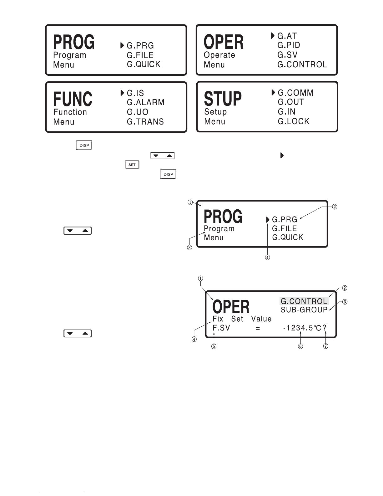
1) Menu displayed on LCD screen consists of groups and sub-groups as blow:
●
Auto & Manual Display
●
Power-On Display
●
Menu Display
① AUTO » MAN indicates that the current output mode is AUTO, MAN » AUTO indicates that the current
output mode is MANUAL.
② If AUTO/MAN is locked, this display is inactive .
※ For instance, if current output mode is AUTO and pressing key will change from output mode to MANUAL
and MAN » AUTO will be displayed.
1) PV Display
D1 D2 D3 D4 D5
2) SV Display
① Characters shown in D1 ~ D3 indicate NP200 model.
② Character show in D4 indicates temperature controller
type (0: Heating; 1: Heating/Cooling)
③ Character show in D5 indicates additional
information of temperature controller
(0: none, 1: Communication,2 : Four Digital Inputs,
3: Communication/Four Digital Inputs)
① Characters in top-left indicate NP200 model,
controller type and additional information.
② Character in bottom indicates Version number.
Menu Group Sub-group
PROG (Program)
G.PRG (Program Group)
G.FILE (File Group)
G.QUICK (Quick Menu Group)
INFORM (Pattern/Segment Information)
PT.EDIT (Pattern Edit)
SEG.EDIT (Segment Edit)
OPER (Operation)
G.AT (Auto-Tuning Group)
G.PID (PID Group)
G.SV (Set-up Group)
G.CONTROL (Control Group)
-
FUNC (Function)
G.IS (Inner Signal)
G.ALARM (Alarm Group)
G.UO (User Output Group)
G.TRANS (Transfer Group)
-
STUP (Set-up)
G.COMM (Communication group)
G.OUT (Output group)
G.IN (Input Group)
G.LOCK (Locking group)
-
15
① Pressing key will alter Menu displays.
② Sub-groups are displayed on left. Use key to change the required sub-group ( indicates the selected
Sub-Group Menu). Pressing key will confirm the selected sub-group.
③ For returning back to Menu display, press key.
2) Menu Display Parameters
3) Group Display Parameters
① This display indicates the Menu name.
② This display indicates the Group name.
③ This display indicates the full name of Menu.
④ Use key to change the required
sub-group.
① This display indicates the Menu name
② This display indicates the Group name.
③ This display indicates the Sub-Group .
④ This display indicates the full name of Parameter.
⑤ This display indicates the Parameter name.
⑥ This display indicates the Parameter value.
⑦
Use key to change the Parameter value.
?-display blinks when the Parameter value is changed.

16
QUICK
1) Operation screen
AT.M
AT ALPHA
PIDSL
ARW SVNO LEVEL
SV1 TIME
SV2
END TIME
SV3 DI
SV4
PWR.MD
1.P 2.P 3.P 4.P
PLDSL=1 PLDSL=2 PLDSL=3 PLDSL=4
1.I 2.I 3.I 4.I
1.D 2.D 3.D 4.D
1.MR 2.MR 3.M 4.MR
1.Pc 2.Pc 3.Pc 4.Pc
1.Ic 2.Ic 3.Ic 4.Ic
1.Dc 2.Dc 3.Dc 4.Dc
1.DB 2.DB 3.DB 4.DB
1.LVL 2.LVL LVLD
b
a
c
k
s
i
d
e
* 5th operation screen
would not be displayed
when LOCK A/M=0.
SV screen
OUT screen
GRAPH screen
USER OUT screen
AUTO/MAN
Power ON
3 s
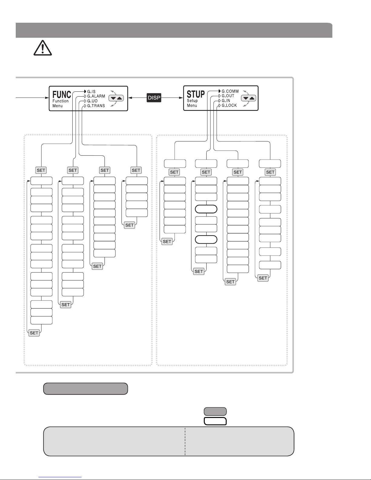
7. Menu Display
2) Menu screen
Caution
Prior to the other group settings, “Input Group (G.IN)”, then “Output
Group (G.OUT)” should be set firstly.
If other groups are set before Input group or Output group setting, the
value should be changed according to the Input / Output setting value.
17
IS.MD AL.MD U1
U4
U7
U2
U5
U8
U3
U6
U9
U10
IS1
IS2
IS3
IS4
IS5
A1TY
A2TY
A3TY
A4TY
TRANS
PWD PWD
OUT
HYS
OL-H
PR-S INP
STP FR-H
RJC
RP.T SL-H
B.OUT
▽/△
PROG
O.ACT
HEO
P.INIT
OL-L
BPS UNIT
DLN FR-L
FILT
PT.NO
OPER
HCT
CCT
CEO
PRI U.UNIT
SL-L
ADR DP-P
BIAS
RUN
FUNC
PWD.C
A/M
PWD PWD
ADJ.H
IS1H
IS2H
IS3H
IS4H
IS5H
A1DB
A2DB
A3DB
A4DB
TRANS.H
ADJ.L
IS1L
IS2L
IS3L
IS4L
IS5L
AL-1
AL-2
A3-3
AL-4
TRANS.L
●Menu Setting Screen
- Menu setting is recommended after program operation is off.
- It is to prevent setting value changed according to a certain set-up parameter setting.
- Some parameter may not indicated due to its mode & additional specification of controller,
control type selection etc.
The controller starts from the same operating mode as
when the device was OFF. But if the device was in
program mode, will follow ST.MD
: OPTION
: H/C TYPE시
• AUTO operation MODE : Starts control from HEO set value
• MAN operation MODE : Starts control from
HEO set value
* : In ON/OFF (OUT=0) control SKIP
In MAN control, AT GROUP is
● When power is ON
CAUTIION
*
*
*
*

18
SV screen
OUT - screen
GRAPH screen
USER OUT screen
AUTO/MAN screen
Power ON
3 s
3 s
1~30
0~99
SEG.NO=0 SEG.NO=1 SEG.NO=2
SEG.NO=99
PT.NO
SEG.NO
WZ 1.PID 2.PID 99.PID
1.ALM 2.ALM
99.ALM
1.SV 2.SV 99.SV
1.TM 2.TM 99.TM
1.TS1 2.TS1 99.TS1
1.TS1 ON 2.TS1 ON 99.TS1 ON
1.TS2 ON 2.TS2 ON 99.TS2 ON
1.TS3 ON 2.TS3 ON 99.TS3 ON
1.TS4 ON 2.TS4 ON 99.TS4 ON
1.TS5 ON 2.TS5 ON 99.TS5 ON
1.TS1 OFF 2.TS1 OFF
99.TS1 OFF
1.TS2 OFF 2.TS2 OFF
99.TS2 OFF
1.TS3 OFF 2.TS3 OFF
99.TS3 OFF
1.TS4 OFF 2.TS4 OFF
99.TS4 OFF
1.TS5 OFF 2.TS5 OFF
99.TS5 OFF
1.TS2 2.TS2 99.TS2
1.TS3 2.TS3 99.TS3
1.TS4 2.TS4 99.TS4
1.TS5 1.TS5 99.TS5
REPEAT
TS.MD
ST.SV
END.SEG
END.MD
END.TM
END.PT
WTM
ST.MD
1) Operation screen
* 5th operation screen
would not be displayed
when LOCK A/M=0.
2) menu screen

19
INFORM PT.EDIT SEG.EDIT
PT.NO
USE
G.PRG
G.FIL
G.AT
G.PID
G.SV
G.CTRL
G.IS
G.ALARM
G.UO
G.TRANS
G.COMM
G.OUT
G.IN
G.LOCK
INSERT
DELETE
COPY S
USED/
TOTAL
Pattern
USED/
TOTAL
Segment
USED
Segment
by Pattern
PT.n
COPY D
DELETE
F.INIT
*1
Starts operation from operation mode before Power off. But in program mode,
operation will be followed by ST.MD.
*If you ON USE menu, display will be
changed as below (Group will be
display only ON menu).
*
● Operation when Power ON
• AUTO operation MODE: Starts from HEO set value
•
MAN operation MODE: Starts from HEO set value
*1 PATTERN number selection (1~3)
by Keys with DIRECT ENTRY

20
8. Setting Guidline
CAUTION
Prior to the other group settings, “Input Group (G.IN)”,
then “Output Group (G.OUT)” should be set firstly.
If other groups are set before Input group or Output group setting, the value should
be changed according to the Input / Output setting value.
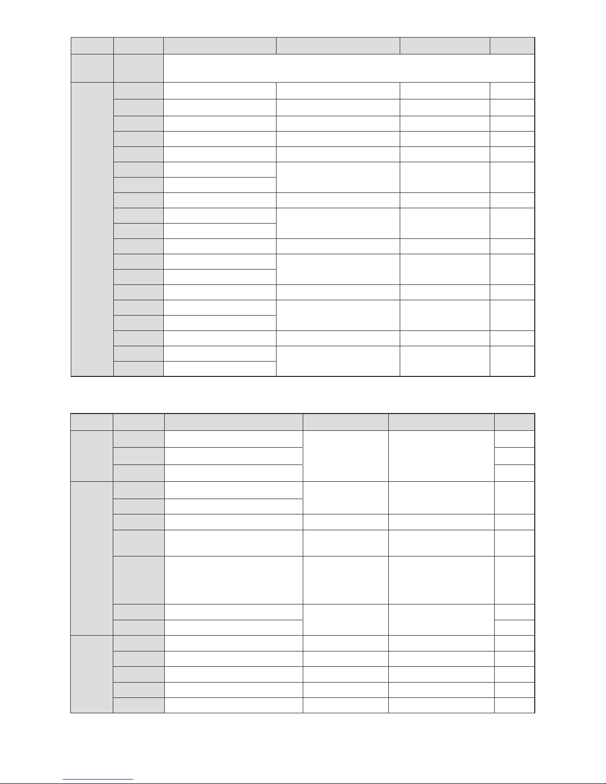
8-1. Program Menu(PROG)
●
Program Group (G.PRG)
Classification
Signal Parameter Set-up range Display Condition Default
Entry
PT.NO Pattern Number Selector 1 ~ 30
Always
1
SEG.NO Segment Number Selector
0 ~ 99 0
WZ Wait Zone
OFF, 0 ~ 10 % (EUS) OFF
WTM Wait Time
OFF, 0.01 ~ 99.59 (TIME) OFF
REPEAT Repeat Set
CONTINUE / 1 ~ 99 1
TS.MD Time Signal Mode NONE, ON/OFF1~5, TIME1~5 ON/OFF1
ST.SV Start Set Value
0 ~ 100 % (EU) EU (0 %)
ST.MD Start Mode
SSV, PV1, PV2 SSV
END.SEG Pattern End Segment
OFF, 1 ~ 99
OFF
END.MD Pattern End Mode
RESET, HOLD, FIX, LINK RESET
END.TM End Signal Time
OFF, 0.01 ~ 99.59 (TIME) OFF
LINK.PT Link Pattern
1 ~ 30
END.MD = LINK 1
01. PID 01. PID NO. Select
1 ~ 4 Always 1
01. ALM 01. ALM NO.Select
OFF, 1 ~ 15 Always OFF
01. SV 01. Set Value
0 ~100 % (EU)
Always
EU (0 %)
01. TM 01. Segment Time
OFF, 0.00 ~ 99.59 (TIME) OFF
01. TS1 Time Signal 1
OFF, ON Always OFF
TS1 ON 01. TS1 on Time
00.00 ~ 99.59 (TIME)
TS.MD = Time
1.TS1 = ON
00.00
TS1 OFF 01. TS1 OFF Time
01. TS2 Time Signal 2
OFF, ON Always OFF
TS2 ON 01. TS2 on Time
00.00 ~ 99.59 (TIME)
TS.MD = Time
1.TS2 = ON
00.00
TS2 OFF 01. TS2 OFF Time
01. TS3 Time Signal 3
OFF, ON Always OFF
TS3 ON 01. TS3 on Time
00.00 ~ 99.59 (TIME)
TS.MD = Time
1.TS3 = ON
00.00
TS3 OFF 01. TS3 OFF Time
01. TS4 Time Signal 4
OFF, ON Always OFF
TS4 ON 01. TS4 on Time
00.00 ~ 99.59 (TIME)
TS.MD = Time
1.TS4 = ON
00.00
TS4 OFF 01. TS4 OFF Time
01. TS5 Time Signal 5
OFF, ON Always OFF
TS5 ON 01. TS5 on Time
00.00 ~ 99.59 (TIME)
TS.MD = Time
1.TS5 = ON
00.00
TS5 OFF 01. TS5 OFF Time
SEG. NO = 0SEG. NO = 1
21
Classification
Signal Parameter Setting range Display condition Default
INFORM
Pattern USED / TOTAL (30)
DISPLAY ONLY Always
0 / 30
Segment USED / TOTAL (300)
0 / 300
PT. n Used Segment by Pattern
0 / 0
PT. EDIT
COPY. S Copy Source
OFF / 1 ~ 30
Pattern
Always
COPY. S ≠ OFF
OFF
COPY. D Copy Destination
RESULT Result of File
– COPY. S = 1 ~ 30 -
DELETE Delete Pattern Number OFF / 1 ~ 30
Pattern
COPY. D = 1 ~ 30 OFF
RESULT Result of File CMD –
COPY. S = 1 ~ 30
COPY. D = 1 ~ 30
DELETE = 1 ~ 30
-
F.INIT File All Initialize
(Program initializing)
NO, YES Always
OFF
CONFIRM Really File Init ?
ON
SEG.
EDIT
PT. NO Pattern Number Select
1 ~ 30 Pattern Always 1
INSERT Insert Segment Number
OFF / 1 ~ 99 seg PT.NO = 1 ~ 30 OFF
RESULT Result of File CMD
- INSERT = 1 ~ 98 -
DELETE Delete Segment Number
OFF / 1 ~ 99 seg Always OFF
RESULT Result of File CMD
– DELETE = 1 ~ 99 -
Classification
Signal Parameter Set-up range Display Condition Default
SEG. NO
= 2~98
99. PID PID NO. Select
1 ~ 4 PID control level=OFF 1
99.ALM ALM NO.Select
OFF, 1~15 Always OFF
99. SV Set Value 1 0 ~ 100 % (EU) Always EU (0 %)
99. TM Segment Time 1 OFF, 0.00 ~ 99.59 (TIME) Always OFF
99. TS1 Time Signal 1 OFF, ON Always OFF
TS1 ON TS1 ON Time
00.00 ~ 99.59 (TIME)
TS.MD = Time
99.TS1 = ON
00.00
TS1 OFF TS1 OFF Time
99. TS2 Time Signal 2 OFF, ON Always OFF
TS2 ON TS2 ON Time
00.00 ~ 99.59 (TIME)
TS.MD = Time
99.TS2 = ON
00.00
TS2 OFF TS2 OFF Time
99. TS3 Time Signal 3 OFF, ON Always OFF
TS3 ON TS3 ON Time
00.00 ~ 99.59 (TIME)
TS.MD = Time
99.TS3 = ON
00.00
TS3 OFF TS3 OFF Time
99. TS4 Time Signal 4 OFF, ON Always OFF
TS4 ON TS4 ON Time
00.00 ~ 99.59 (TIME)
TS.MD = Time
99.TS4 = ON
00.00
TS4 OFF TS4 OFF Time
99. TS5 Time Signal 5 OFF, ON Always OFF
TS5 ON TS5 ON Time
00.00 ~ 99.59 (TIME)
TS.MD = Time
99.TS5 = ON
00.00
TS5 OFF TS5 OFF Time
SEG. NO = 99
●
File Group (G.FILE)

22
Menu
Code
Parameter Setting Range Display Condition
Default
Value
G.QUICK
USE Quick menu use or not
OFF / ON Always
OFF
G.PRG
PRG Group use or not
ON
G.FILE FILE Group use or not
G.AT
AT Group use or not
G.PID
PID Group use or not
G.SV SV Group use or not
G.CTRL CTRL Group use or not
G.IS IS Group use or not
G.ALARM ALARM Group use or not
G.UO UO Group use or not
G.TRANS TRANS Group use or not
G.COMM COMM Group use or not
G.OUT OUT Group use or not
G.IN IN Group use or not
G.LOCK LOCK Group use or not
Menu Code Parameter Setting Range Display Condition
Default
Value
AT. MD Auto Tuning Mode Selection STD, LOW *1 AUTO & PID STD
AT Auto Tuning OFF, ON, Auto (*2) AUTO & PID제어시 OFF
8-2. Operating Menu (OPER)
●
Auto tuning Group (G.AT) : Only display when program operation status
●
PID Group (G.PID)
✽1 ; Low : Auto Tuning Starts as -10% of SV ✽2 Auto is displayed when LEVEL=ON in Control Group
Menu Code Parameter Setting Range
Display
Condition
Default
Value
ARW Anti - Reset Wind up AUTO, 50.0 ~ 200.0 % PID Control 50.0
ALPHA Alpha 0 ~ 100 PID Control 50
PIDSL PID Group Select
0 ~ 4 (Set 1 ~ 4 to move to next parameter
) PID Control 0
n.P Proportional band 0.1 (H/C Type : 0.0) ~ 999.9 % PID Control 5.0 %
n.I Integral time
OFF / 1 ~ 6000 s (Sec.) PID Control
240 s
n.D Derivative time 60 s
n.MR Manual reset -0.5 ~ 105.0 % (%) I = OFF 50.0%
n.Pc
Proportional band of cooling side
0.0 (ON/OFF control) / 0.1 ~ 999.9 %
HC TYPE
5.0 %
n.Ic Integral time of cooling side OFF / 1 ~ 6000 s 240 s
n.Dc
Derivative time of cooling side
OFF / 1 ~ 6000 s 60 s
n.DB
Dead band of Heating-Cooling side
-100.0 ~ 50.0 % 3.0 %
n.LVL PID Level n
EU (0) ≤ 1.LVL ≤ 2.LVL ≤ EU (100 %) (EU)
LEVEL = ON EU (100%)
LVLD Reference DEV OFF / EUS (0 ~ 100 %) (EU) LEVEL = ON EUS (0.5%)
●
Quick Menu Group (G.QUICK)
● Using of Auto Tuning
- Please do not use Auto Tuning as following controls
- Quick response controller such as flow control and press control
- Controller output should not be ON /OFF even for a short time.
- Controller should not have big load to the control part
- Fluctuation of set value gives bad effect on product quality
Caution

23
Menu Code Parameter Setting Range
Display
Condition
Default Value
FIX SV
SVNO Set Value NO, Select 1 ~ 4 Always 1
SV1 Set Value 1
EU (0 ~ 100 %) (EU) Always EU (0 %)
SV2 Set Value 2
SV3 Set Value 3
SV4 Set Value 4
Menu Code Parameter Setting Range
Display
Condition
Default Value
LEVEL Level PID OFF, ON PID OFF
TIME Time Unit HH:MM, MM:SS Always HH.MM
END.TM Time Unit HH:MM, MM:SS Always HH.MM
DI Digital Input Enable OFF / ON DI OPTION시 OFF
PWR. MD Power ON Mode HOT, COOL Always COOL
Menu Code Parameter Setting Range
Display
Condition
Default Value
IS.MD Inner Signal Mode TSV, NSV, PV
Always
TSV
IS1
IS1 Inner Signal 1 OFF, ON OFF
IS1H Inner Signal 1 High IS1L + 1digit + EU (100 %)
IS1 = ON
EU (100 %)
IS1L Inner Signal 1 Low EU (0 %) ~ IS1H - 1digit EU (0 %)
IS2
IS2 Inner Signal 2 OFF, ON Always OFF
IS2H Inner Signal 2 High IS2L + 1digit + EU (100 %)
IS2 = ON
EU (100 %)
IS2L Inner Signal 2 Low EU (0 %) ~ IS2H - 1digit EU (0 %)
IS3
IS3 Inner Signal 3 OFF, ON Always OFF
IS3H Inner Signal 3 High IS3L + 1digit + EU (100 %)
IS3 = ON
EU (100 %)
IS3L Inner Signal 3 Low EU (0 %)~ IS3H - 1digit EU (0 %)
IS4
IS4 Inner Signal 4 OFF, ON Always OFF
IS4H Inner Signal 4 High IS4L + 1digit + EU (100 %)
IS4 = ON
EU (100 %)
IS4L Inner Signal 4 Low EU (0 %) ~ IS4H - 1digit EU (0 %)
IS5
IS5 Inner Signal 5 OFF, ON Always OFF
IS5H Inner Signal 5 High IS5L + 1digit + EU (100 %)
IS5 = ON
EU (100 %)
IS5L Inner Signal 5 Low EU (0 %) ~ IS5H - 1digit EUS (0 %)
●
Set Value Group (G.SV)
●
Control Group (G.CONTROL)
8-3. Function Menu (FUNC)
●
Inner Signal Group (G.IS)
 Loading...