

HANYOUNG NUX ML-D2H, ML-D4, ML-D, ML, ML-E Instruction Manual


ABOUT THIS MANUAL
Thank you very much for purchasing HANYOUN NUX product.
This instruction manual includes details of product functionality, installation method,
cautions, usage, and others. Read and be fully aware of contents before use of product.
Also, provide this manual in order for end user use, and at easily accessible place
anytime.
* Contents of this manual are subject to change without prior notice.
* For questions, and errors regarding contents of this manual,
contact our company or business offices.
* Unpermitted reprinting and duplication of all or part of contents of
this manual are strictly prohibited.
■Services (A/S)
* For A/S request of this company’s product, please contact outlets,
sales office nearby or head office of our company.
* If you like onsite visit service, please send the request after speaking
Multi Loop Controller
with A/S Center personnel on the phone.
* Prior to sending request, please check if questions and answers for the same
problems are posted in the FAQ section of homepage.
HANYOUNG NUX
28, 71Beon-gil, Gilpa-ro, Nam-gu, Incheon, 402-205, Korea
TEL : (032)867-0941 (main phone line)
FAX : (032) 868-5899
URL : http://www.hynux.com
E-mail : sdt@hynux.com

TABLE OF CONTENTS
1. Before starting
2. Installation
3. Run
4. Specifications
1.1. Overview
1.2. Product verification
1.3. Safety cautions
2.1. Installation location and cautions
2.2 Exterior dimensions of product
2.3 Connection diagram 8
2.4 Power supply and communications interface(RS485/RS232C)
2.5 Event output unit connections
3.1 Protocol composition
3.2 Register composition
3.2.1 ML-D2H register composition
3.2.2 ML-D2H register description
3.2.3 ML-D4의 register composition
3.2.4 ML-D4 register description
3.3 Manipulation and working
3.3.1 Input section
3.3.2 Control section
3.3.3 Event section
3.3.4 Status indication and set up
3.3.5 Warning occurrence and handling
11
12
18
18
20
25
27
32
32
34
40
44
47
48
2
Before staring Installation Operation Specifications
2
4
5
6
9
1
1. BEFORE STARTING
1.1 Overview
■ML Series product family
Multi-channel temperature control system (ML-D, ML-D2H), event output (ML-E)
■ Module composition method (Individual product is called “Unit”)
ML Series products can be made up as one module by connecting maximum of 31 units without wiring
work, and only one Unit is connected to power cable and communications line (RS485). Event output
(ML-E) is not included in maximum connection quantity, and only one Unit is connected during module
composition and used.
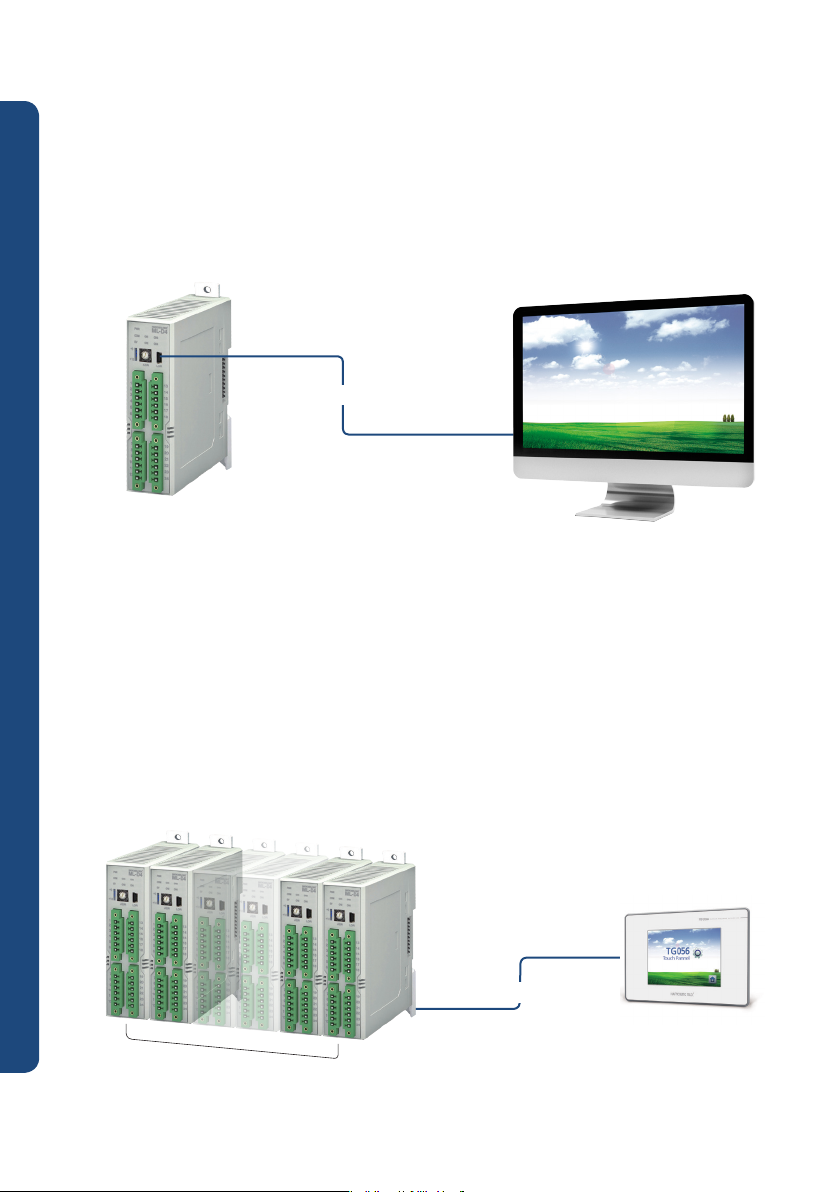
■ Product run through communications connection
For RS232C and RS485 communications method, this product supports PC-Link, PC-Link with SUM,
Modbus, ASCII/RTU protocols. Through individual communication with product, it is operated with
reading/writing of Register address defined based on function. Basic functions such as control and
monitoring can be tested or operated using operating program provided in the computer.
RS485 communications : For use, connect to communications terminal at low part, and this standard is
used when operating multiple units since communications are achieved only
through address set as switch in front side.
RS232C communications : For use, connect to Loader Jack at front part, and only connected unit is
communicated regardless of front side switch setup. It is for unit’s initial setting.
■ Input type
Thermocouple (12 types) : K, J, E, T, R, B, S, L, N, U, W, PL2
RTD (2 types) : Pt100, KPt100
DC voltage (3 types) : 0 – 10 V, 1 -5 V, 0 – 100 mV
Direct current (4 – 20 mA) : Set input type as direct current (1 -5 V), attach 250 Ω of electric resistance
at both ends of input terminal
Current Transformer (CT) : 2 channel, AC 1 – 50A (primary current measuring range), apply only to ML-D2H
■ Control output type
Depending on output type of model composition, fixed in one among REALY, voltage pulse (SSR), and
Multi Loop Controller
current output (SCR).
■ Control method
2 DOF (Degree of Freedom) PID control (auto tuning support), ON/OFF control
ML-D2H: 2 Channel, Universal control (Selectable Heating or cooling control) or Heating/Cooling
simultaneous controlling
ML-D4: 4 Channel, Universal control (Selectable Heating or cooling control)
■ Installation
Can attach onto panel by fixing in DIN 35 mm standard rail or using screw
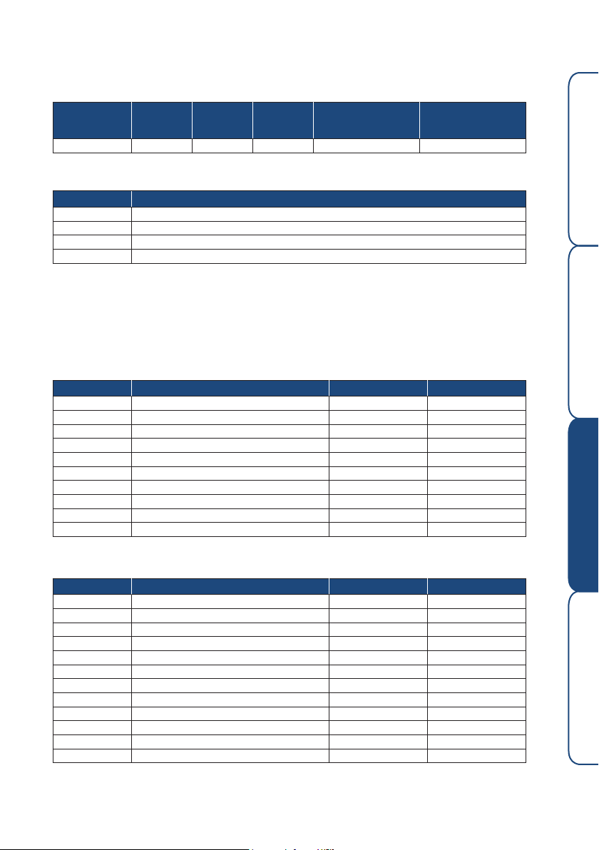
1.2 Product verification
For product purchase, please first verify desired specifications, and then damages in exterior and parts
insufficiency. And contact sales department of this company if found different specifications, exterior damage, or
parts insufficiency.
ML - SERIES
Module Type Temperature Control System
INSTRUCTION MANUAL
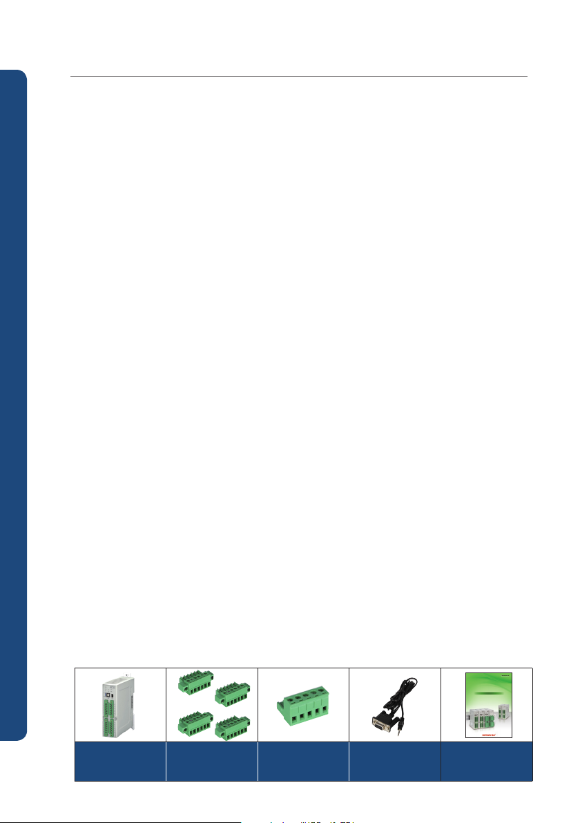
Body
6-pin terminal
4 EA
5-pin terminal
1 EA
2
RS232C
communications cable
(optional)
Instruction manual
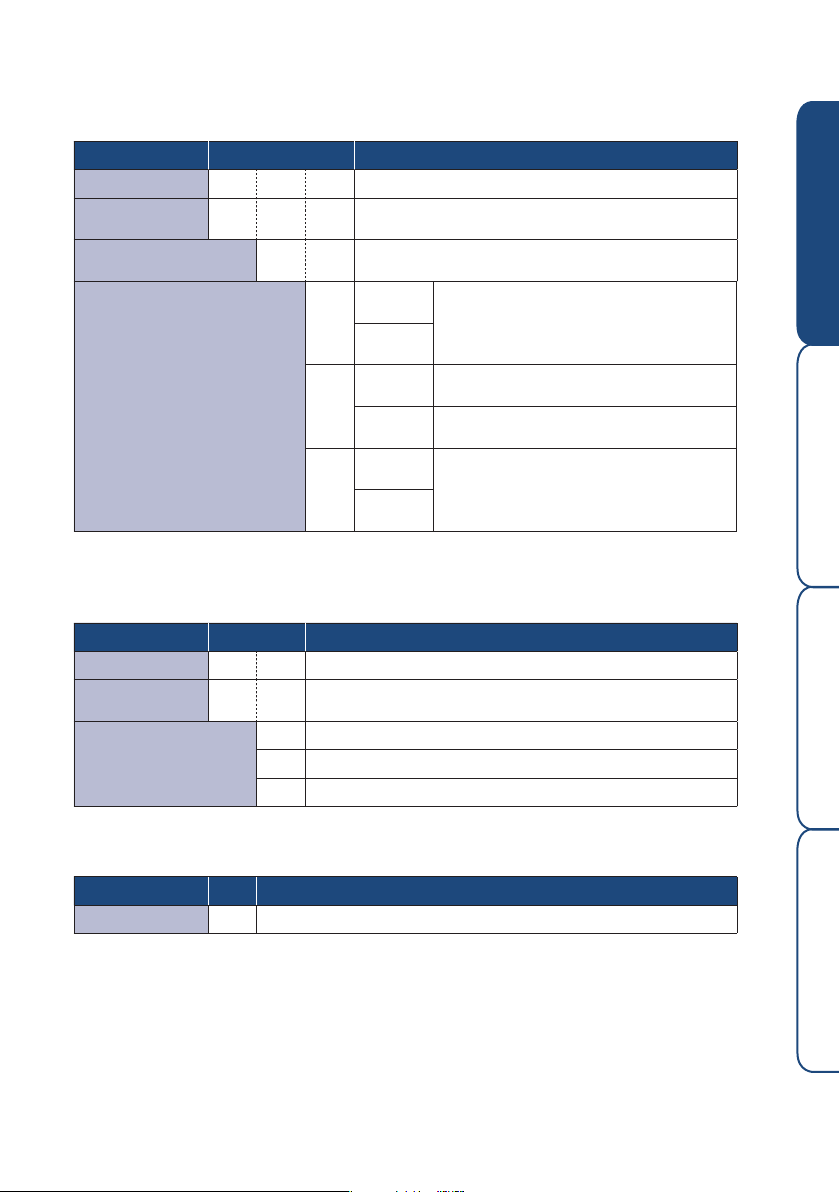
1.2.1 Model composition
■ Module type temperature controller (ML-D2H)
Model Code Details
ML-D 2 H ☐ Module type temperature controller
Number of
channels
Function H
Output type
█ Module type temperature controller (ML-D4)
Model Code Details
ML-D ☐ ☐ Module type temperature control system
Number of
channels
Output type
Ex: Temperature control system 4 channel relay output : ML-D4M
2 2 channel
Heating/cooling control (simultaneous), heater break
alarm (HBA)
OUT1
(heating)
MM
OUT2
(cooling)
OUT1
(heating)
SM
OUT2
(cooling)
OUT1
(heating)
SS
OUT2
(cooling)
4 4 channel
M Relay output
S SSR output (12 V d.c.)
C SCR output (4 -20 mA d.c.)
Relay output
SSR / SCR (4 -20 mA d.c.)
parameter optional output
Relay output
SSR / SCR (4 -20 mA d.c.)
parameter optional output
Before staring Installation Operation Specifications
█ Module type event output (ML-E)
Model Code Details
ML- E Module type event output unit
3

1.3. Safety Cautions
1.3.1 Cautions for safety
● For protection and safety of product and system connected to product,
please use product according to safety instructions of this manual.
● The company will not be held responsible for all safety related issues and loss caused by
carelessness and others, for use or treatment not following directions of instruction manual.
● For protection and safety of product and system connected to product, if required to install
additional safety circuit and others, please make sure to install on external side of this product.
● Do not disassemble, repair, and renovate at self discretion,
as it may cause product damage and malfunctions.
● Do not give shock to product, this can cause product damage or malfunction
1.3.2 Quality assurance
● Unless specified in terms of quality assurance of this company, no guarantee or compensation
will be provided for this product.
● If damage is caused to user or third party due to defects and inevitable accidents that are
impossible to predict by this company, the company, on any occasion, will not be responsible
for loss, indirect damages, and others
1.3.3 About quality assurance terms of this product
● Product warranty period is one year from purchase date of this product, and for breakdowns
occurred during normal usage according to this instruction manual, free repair service will be
provided for such product only.
● For repair to breakdowns occurred after warranty expiration of this product,
it will be repaired at cost (actual expense), based on company specified guidelines.
● For problems below, repairs will be provided at cost even for breakdown during
Multi Loop Controller
warranty repair period.
- Breakdown due to user’s fault
- Breakdown due to natural disasters
- Breakdown due to transfer and others after product installation
- Breakdown due to improper product modifications or losses
- Breakdown due to power supply problem such as power supply instability
● If A/S is required due to breakdown and others, please contact purchase outlet and
our company sales department.
4

2. Installation
2.1 Installation place and cautions
2.1.1 Installation place
● To avoid risk of electric shock, use after panel penal is installed to this product.
● Do not install product at following places.
- Place that people can come into contact with terminal without awareness.
- Place directly exposed to mechanical vibrations or shocks
- Place exposed to corrosive gas or combustible gas
- Place with large change of temperatures
- Place with overly high temperature or low temperature
- Place exposed with direct sun light
- Place greatly influenced by electronic wave
- Place high in humidity
- Place with combustible items in surroundings in the event of fire
- Place with a lot of dust or salinity
2.1.2 Caution
● In case of wiring, cut off power sources of all instruments before start of wiring work
● This product operates at DC24 V. There is danger of electric shocks and fire if other than
rated power supply is used.
●To use ML Series as one module by connecting several units, connect power to only one unit.
● When connecting DC 24 V power source, use rated power supply by calculating total power
consumption of module to use. Using power supply less than total power consumption of
module can cause abnormal run and malfunction.
● Do not operate with wet hands as there is risk of electric shocks.
● For installation and usage, follow directions specified in instruction manual.
● Do not supply power before connection for devices of this product is completed.
● Do not block heat opening of this product as it can cause breakdown.
● Make sure not to touch terminal when current is flowing as there is risk of electric shock.
Before staring Installation Operation Specifications
100
100
• For module body installation
mm
or separation, please secure
proper interval of over 100 mm
considering communications
terminal connector and others.
mm
5

2.2 Connection diagram
2.2.1 Name of each part
█ ML-D2H
③
④
⑤
⑥
⑨
█ ML-D4
Multi Loop Controller
③
④
⑤
⑥
⑨
No. Name Function
①
① Status indication LED
②
② Loader Jack
③ Unit address switch
⑦
Unit extension
④
address switch
⑤
⑧
※ If unit extension address switch is positioned at “+16” and unit address
switch is positioned at “1,” RS485 communications address is set to “1+16=17.”
CH 1 terminal
⑥
⑦
CH 2 terminal
⑧
Power source and
⑨
communications
termina
Power supply, communication, event, control
output, heater break event indication
RS232C communication input terminal
RS485 communication address setting switch
(0~15)
RS485 communication extension address setting
switch (0 /+16)
Temperature input and current transformer (CT)
input terminal
OUT 1: heating control output terminal
OUT 2: cooling control output terminal
Temperature input and current transformer (CT)
input terminal
OUT 1: heating control output terminal
OUT 2: cooling control output terminal
RS485 communications and 24 V d.c. input
terminal
①
No. Name Function
②
① Status indication LED
② Loader Jack RS232C communication input terminal
⑦
③ Unit address switch
Unit extension
④
address switch
⑤ CH 1 terminal
⑧
⑥
CH 2 terminal
⑦ CH 3 terminal
⑧ CH 4 terminal
Power supply and
⑨
communications
terminal
※ If unit extension address switch is positioned at “+16” and unit address
switch is positioned at “1,” RS485 communications address is set to “1+16=17.”
Power supply, communication, event,
control output indication
RS485 communication address setting switch
(0~15)
RS485 communication extension address
setting switch (0 /+16)
Input signal (sensor)
Temperature input and control output terminal
RS485 communications and
24 V d.c. input terminal
6
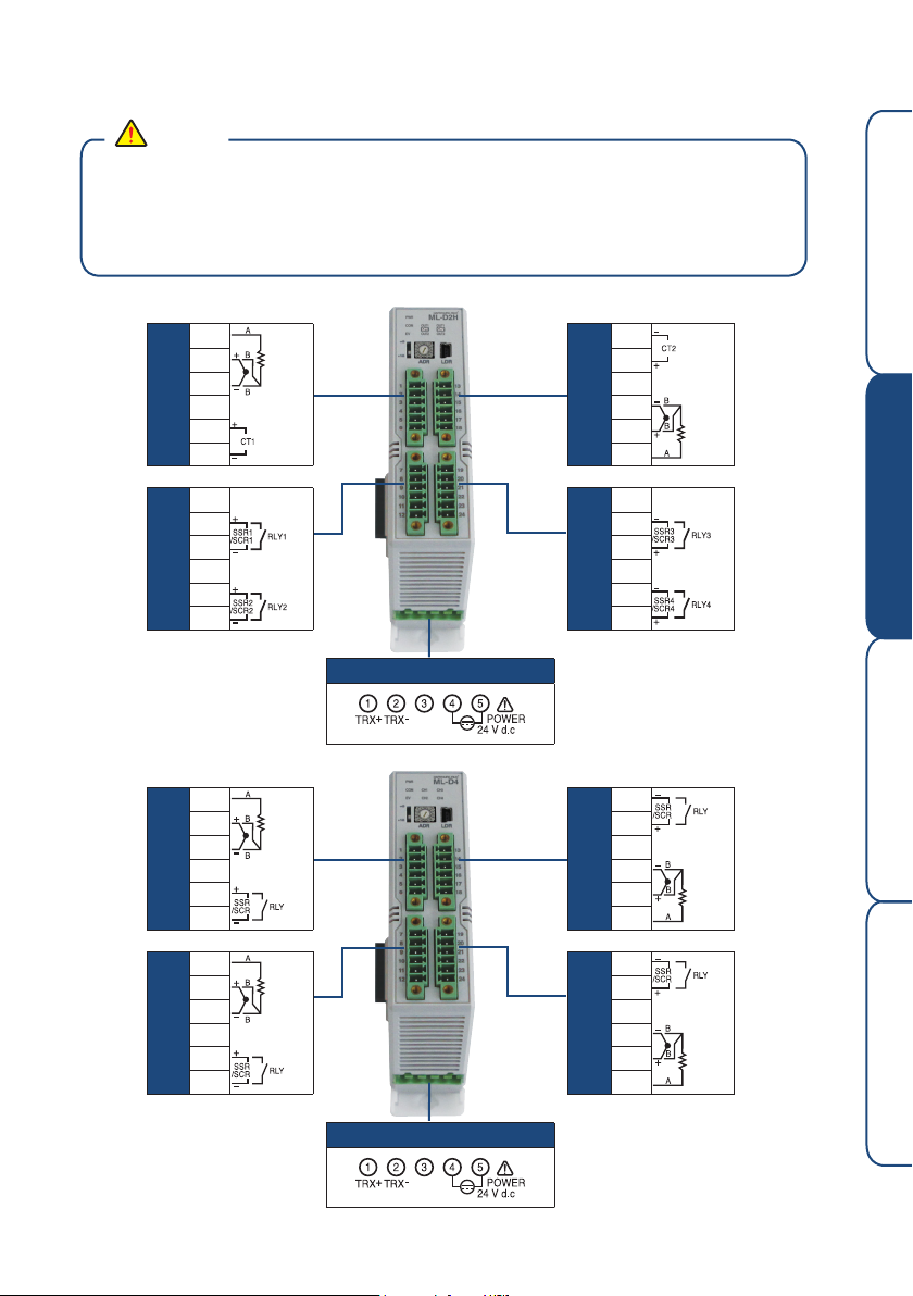
2.2.2 Connection method
Caution
● Before connecting devices, make sure that current is not flowing through connection cable
by cutting off voltage to all instruments to be supplied with power
● As there is danger of electric shock while current is flowing, make sure not to touch terminal.
● Make sure to connect after disconnecting power source voltage.
● For users, do not touch other than above mentioned terminals here.
● ML-D2H
Before staring Installation Operation Specifications
● ML-D4
1 CH
1 CH
1 CH
2 CH
1
2
3
4
5
6
7
OUT1
8
9
10
OUT2
11
12
Power supply section
13
14
15
2 CH
16
17
18
19
OUT2
20
21
2 CH
22
OUT1
23
24
※ 24 V d.c. terminal
has no polarity of (+)
(-) for power supply
connection
1
INPUT
2
3
4
OUT
5
6
7
INPUT
8
9
10
11
OUT
12
3 CH
4 CH
13
14
15
16
17
18
19
20
21
22
23
24
OUT
INPUT
OUT
INPUT
Power supply section
※ 24 V d.c. terminal has
no polarity of (+) (-) for
power supply connection
7
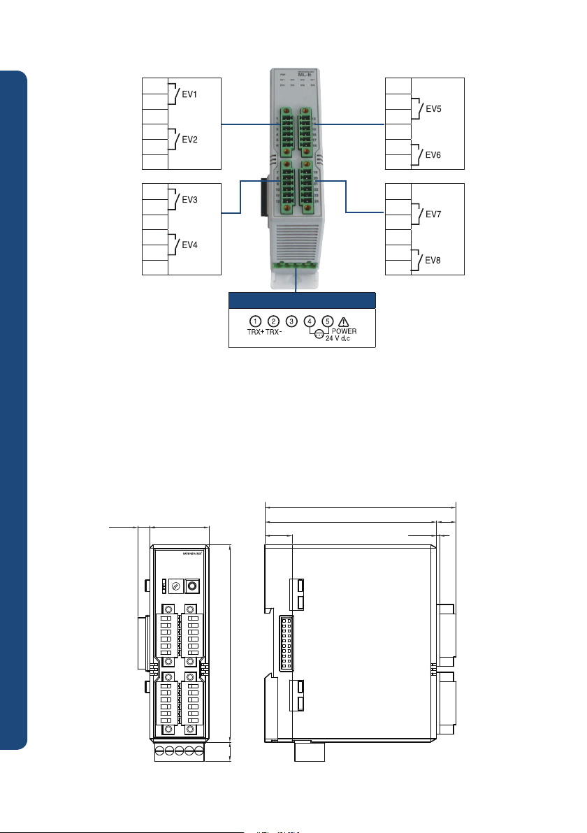
● ML-E
1
2
3
4
5
6
7
8
9
10
11
12
2 . 3 E x t e r i o r d i m e n s i o n
Multi Loop Controller
30.006.00
Power supply section
87.00
13
14
15
16
17
18
19
20
21
22
23
24
※ 24 V d.c. terminal
has no polarity of (+)
(-) for power supply
connection
Unit : ㎜
96.90
9.90
1.5013.75
PWR
ML-D4
COMEVCH1
CH3
CH2
CH4
+0
+16
ADR
LDR
100.009.70
The dimensions of ML-D2H and ML-D4 are same
※
8

2.4 Power supply and communications interface (RS485/RS232C)
Master
TRX+
TRX-
TRX+
TRX-
TRX+
TRX-
TRX+
TRX-
24 V
GND
24 V
GND
24 V
GND
24 V
GND
(24 V DC)
2.4.1 Power supply and communications interface
● When using ML Series as one module by connecting several units, supply power cable and
communications line to only one unit. Required maximum power capacity is 32 units X 7 W= 224 W
when making up 32 unit module. (Refer to power supply specification)
<Example of proper use>
● 2 wire type communication and power source connection
Master
Terminating
resisters
TRX+
TRX-
(24 V DC)
24 V
<Example of incorrect use>
M-D Module
Composition
TRX+
TRX+
TRX+
TRX-
TRX-
TRX-
24 V
24 V
24 V
Terminating
resisters
Before staring Installation Operation Specifications
GND
● 4 wire type communication and power source connection
Terminating
resisters
Master
TX+
TX-
RX+
RX-
(24 V DC)
24 V
GND
GND
※ Dotted line is connected
automatically during module
composition.
TRX+
TRX-
24 V
GND
※ Dotted line is connected
automatically during module
composition.
GND
M-D Module
Composition
TRX+
TRX-
24 V
GND
GND
TRX+
TRX-
24 V
GND
Terminating
resisters
9
2.4.2 RS232C communication
RS232C communication is used to control one Unit, and communicates only with Loader Jack.
For RS232C communication, despite Address setting switch, automatic setup is provided such as
communications Address "1", protocal "PC-LINK", communication speed "9,600bps",
start bit "1 bit", data length "8 bit", parity bit "even number”, stop bit "1 bit." Even with RS232C
communication, remote control and monitoring of connected unit is possible.
2.4.3 RS485 communication
Individual control is also possible using RS485 communication with unit address set as Unit
Address switch. Unit address setting is possible from No. 1 to No. 31. For setting below address
Multi Loop Controller
No. 15, unit address switch is set from No. 1 to No. 15 with unit address extension switch "+0"
and for setting address over No. 15, unit address switch No. 0 to No. 15 is set with unit extension
switch positioned at "+16". If unit extension switch is positioned at "+16" and unit address switch
at "1", RS485 communication address is set as "1+16=17".
RS232C
10
RS485
31 Units
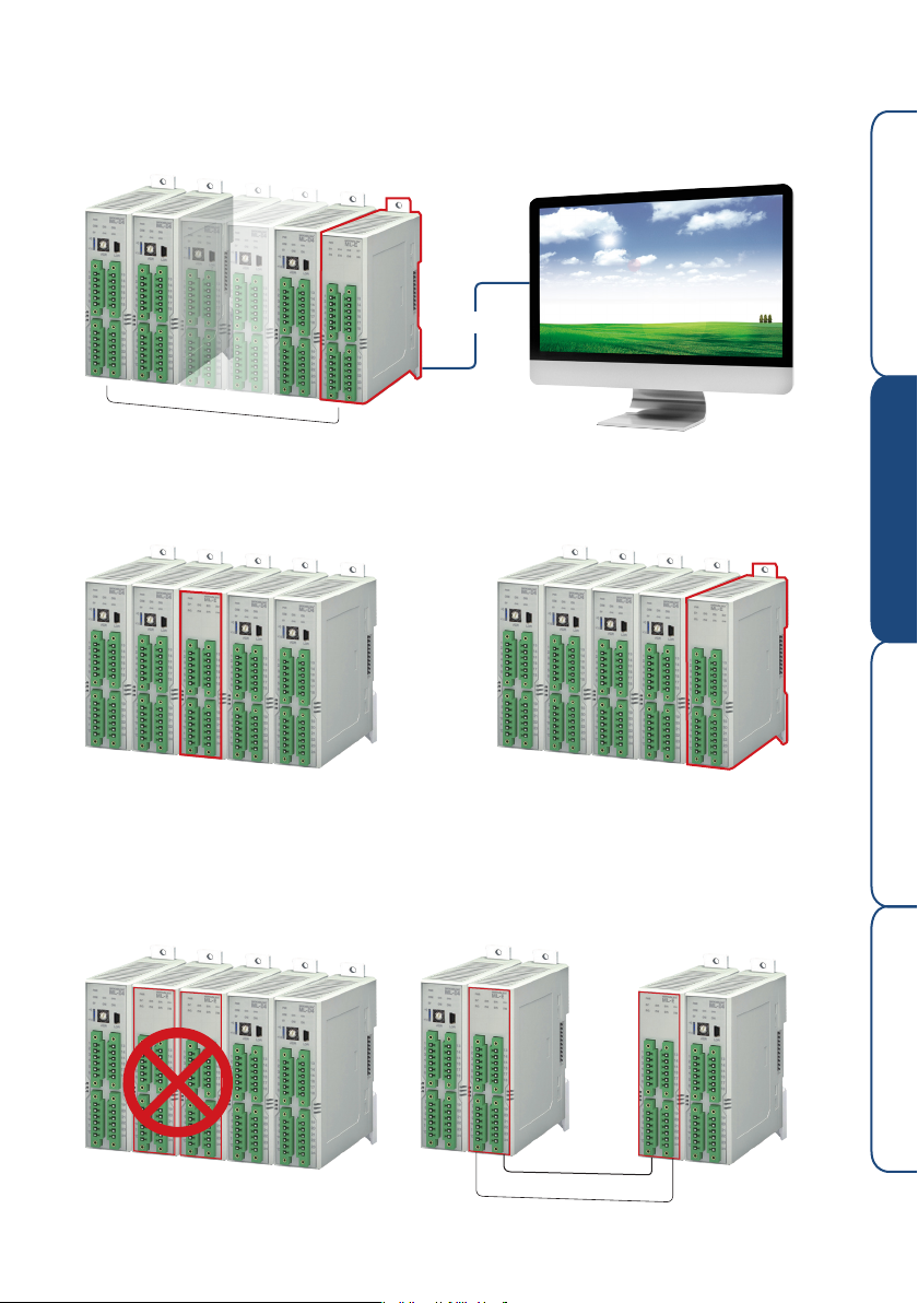
2.5 Event output unit (ML-E) connections
●
ML-E has no communications address, and sends output by receiving signal with side
connector during module composition.
RS485
Before staring Installation Operation Specifications
Mamimum 32 units
(Max. 31: if ML-E not included)
●
ML-E can be located and connected anywhere during module composition.
ML-E
●
When making up as one module, only 1 unit should be connected.
ML-E
ML-E
If several units of ML-E need to be used, it can be achieved by connecting power supply cable
and communication line with wiring method, instead of side connector.
ML-E
Power supply line
Communications cable
11
3. Run
3.1 Protocol composition
● Overview
- This product supports RS232C/485 communications, basic functions can be tested or operated
such as control, monitoring, and others using operating program provided in the computer.
- Protocols supported include PC-Link, PC-Link with SUM, Modbus, ASCII, Modbus RTU.
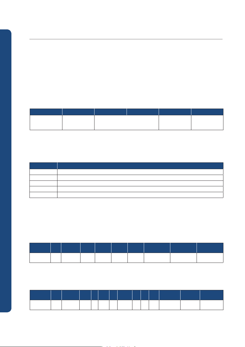
3.1.1 PC-LINK protocol
- Communication of product is performed with ASC II character string, defined Register can be read and written.
<Frame structure>
STX Address Command Data CR LF
STX 01 ~ 99 Refer to each Command 0x0D 0x0A
● Communications command
- This product uses following communication Command.
Command Detail
D R S D Register consecutive reading
D R R D Register random reading
D W S D Register consecutive writing
D W R D Register random writing
W H O Indication of own information
Multi Loop Controller
● Use of communication Command
⑴ DRS Command
- Use when reading value of consecutive D Register
- On frame, enter number of data to be read and D Register number
<Transmission frame>
Byte size
1 2 3 1 2 1 4 1 1
12
Description STX Address DRS
EA : 01~32
D Register : start D Register
<Reception frame>
Byte size
Description STX Address DRS
Data: Hexadecimal number Word data string
1 2 3 1 2 1 4 1 ... 1 4 1 1
,
OK
EA
,
Data(1)
,
D Register CR LF
,
...
,
Data(n) CR LF
,

⑵ DRR Command
- Use when reading random D Register value
- On frame, enter number of data to be read and D Register number on frame
<Transmission frame>
Byte size
1 2 3 1 2 1 4 1 ... 1 4 1 1
Before staring Installation Operation Specifications
Description STX Address DRR
EA : 01~32
EA
,
D Register(1)
,
D Register(n) CR LF
...
,
,
<Reception frame>
Byte size
Description ST X Address DRR
Data: Hexadecimal number Word data string
1 2 3 1 2 1 4 1 ... 1 4 1 1
EA
,
D Register(1)
,
D Register(n) CR LF
...
,
,
⑶ DWS Command
- Use when writing series of D Register values
- On frame, enter number of data to write, D Register number and each data
<Transmission frame>
Byte size
Description STX Address DWS,EA,D Register,Data(1)
EA: 01~15
D Register: start D Register
Data: Hexadecimal number data string
1 2 3 1 2 1 4 1 4 1 ... 1 4 1 1
Data(n) CR LF
...
,
,
<Reception frame>
Byte size
Description ST X Address DWS
1 2 3 1 2 1 1
,
OK CR LF
⑷ DWR Command
- Use when writing random D Register value
- On frame, enter number of data to write and D Register number and each data
<Transmission frame>
Byte size 1 2 3 1 2 1 4 1 4 1 ... 1 4 1 4 1 1
Description
EA: 01~15
Data: Hexadecimal number word data string
STX
Address
DWR,EA,D Register(1),Data(1)
<Reception frame>
Byte size
Description ST X Address DWR
1 2 3 1 2 1 1
D Register(n),Data(n)
...
,
,
,
OK CR LF
CR LF
13
⑸ WHO Command
- Can see product info. with WHO Command
<Transmission frame>
Byte size
Description STX Address WHO CR LFA
1 2 3 1 1
Reception frame
Byte size
1 2 3 1 2 1 - 1 1
Description STX Address WHO
- : Byte size changes depending on model name and version
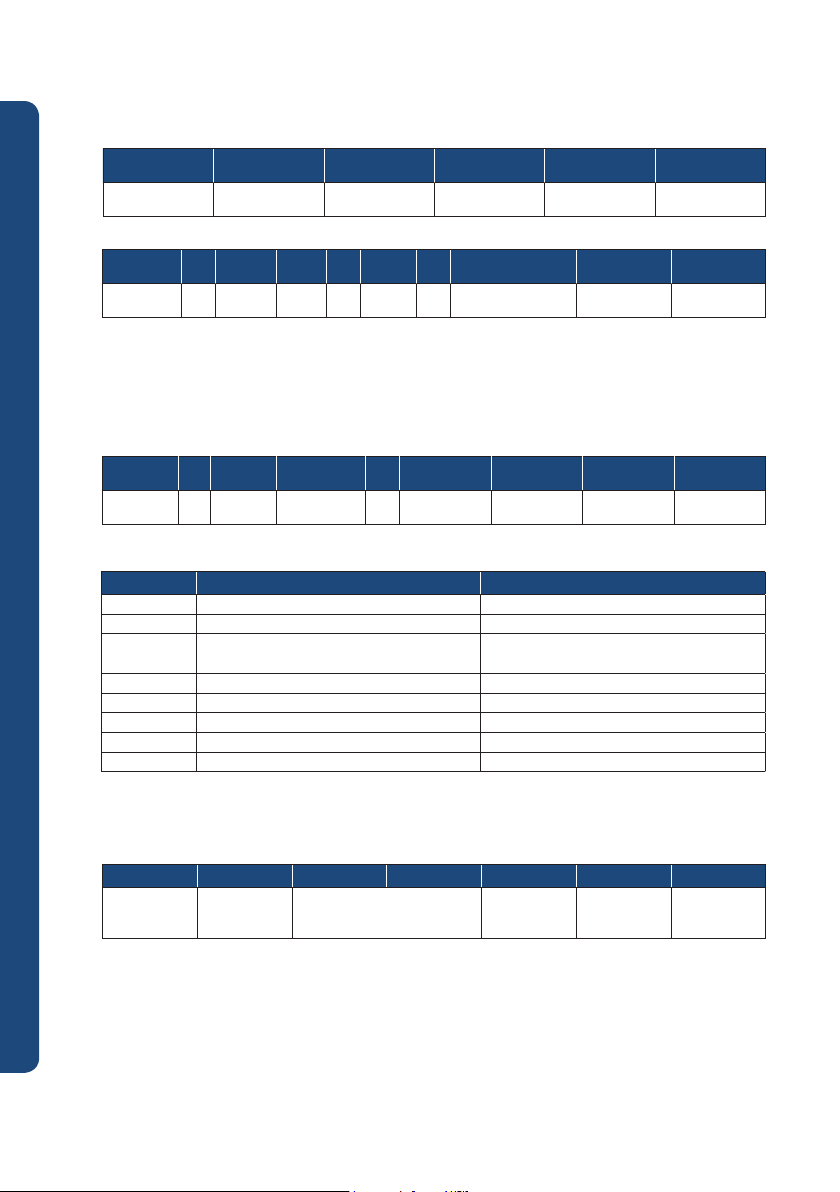
⑹ Reply at error
- When receiving Command, this product transmits reception frame proper to corresponding frame
However, if there is an error in reception Command, following NG Frame is transmitted.
<Transmission frame>
Byte size
Description STX Address Command
- Details of NG Code are as follows
NG Code Name Details
Multi Loop Controller
1 2 3 1 2 2 1 1
0x01 Command Not used Command
0x02 Register Not used Register
0x03 Number
0x04 Data Data is out of Hex (0x0 ~ 0xF)
0x08 Delim Terminating string (CR, LF) error
0x10 SUM Inconsistent SUM value
0x18 Over range Value exceeding provided address scope
0x00 Misc Others
3.1.2 PC-LINK with SUM protocal
- Protocol that CHECK SUM is added to PC-LINK Protocol
<Frame structure>
STX Address Command Data SUM CR LF
STX 01 ~ 99 Refer to each Command
OK
,
,
Name & Version CR LF
,
NG NG Code CR LF
Number of communications and number of
Data do not match
Check
SUM
0x0D
0x0A
14
•
Check Sum is value generated by adding every 1 Byte of string ASCII code until SUM
• Convert generated value into 2 characters of Hexadecimal number
ex) STX 0 1 WH 0 4 F CR LF
Check Sum=4F, Check Sum = “0”(0x30) + “1”(0x31)+”W”(0x57+”H”(0x48)+”O”(0x4F)
=0x30 + 0x31 + 0x57 + 0x48 + 0x4F= 0x14F
As Check Sum is 1byte character, it becomes 0x4F, and then this changes to ASCII Code “4F.”
3.1.3 MODBUS-RTU Protocol
● Frame structure
Frame
heading
character
none 8 bit 8 bit n x 8 bit 16 bit None
CRC : Cyclic Redundancy Check
● Function code
Function code Code detail
03 Register multiple reading (n EA)
06 Register single writing (1 EA)
08 Diagnosis function (LOOP-BACK TEST)
16 Register multiple writing (n EA)
● Function code 03 (READ MULTIPLE REGISTERS)
With function code 03, consecutive register details can be read at once. Number of data to be read at
once varies depending on line condition and transmission speed within the frame. One transmission frame
should be less than 255 bytes.
<Transmission frame>
Serial number Details Size Ex.
0 Frame head character None 1 Device number 8 bit 01 h
2 Function code (03) 8 bit 03 h
3 Reading start register (high) 8 bit 75 h
4 Reading start register (low) 8 bit 36 h
5 Number of data to be read (high) 8 bit 00 h
6 Number of data to be read (low) 8 bit 05 h
7 Frame confirmation CRC (low) 8 bit XX h
8 Frame confirmation CRC (high) 8 bit XX h
9 Frame terminating character None -
Instrument
no.
Function
code
Data
Frame
confirmation CRC
Frame
terminating character
Before staring Installation Operation Specifications
<Reception frame>
Serial number Details Size Ex.
0 Frame head character None 1 Device number 8 bit 01 h
2 Function code (03) 8 bit 06 h
3 Number of data read and transmitted 8 bit dd h
4 Read data 1 (high) 8 bit dd h
5 Read data 1 (low) 8 bit dd h
... ... ... ...
n - 4 Read data n (high) 8 bit dd h
n – 3 Read data n (low) 8 bit dd h
n – 2 Frame confirmation CRC (low) 8 bit XX h
n – 1 Frame confirmation CRC (high) 8 bit XX h
n Frame terminating character None ...
15
 Loading...