

HANYOUNG NUX ML-D, ML-D2H, ML-D4 Instruction Manual
Module type temperature controller
ML-Dseries
MA0617KE161214
INSTRUCTION MANUAL
Thank you for purchasing HANYOUNG product.
Please check whether the product is exactly the same as you ordered.
Before using the product, please read this instruction manual carefully.
Please keep this manual where you can view at any time.
HEAD OFFICE
HANYOUNGNUX CO.,LTD
28, Gilpa-ro 71beon-gil, Nam-gu, Incheon, Korea
TEL : (82-32)876-4697 FAX : (82-32)876-4696
http://www.hynux.com
※ Please refer to the ML-D☐ Instruction Manual for the specific explanation about "Installation and wiring". Also, refer to ML-D☐'s
user Manual in the website for a detailed information.
Safety information
Alerts declared in the manual are classified to Danger, Warning and Caution by their criticality
DANGER
WARNING
CAUTION
•If the user uses the product with methods other than specified by the manufacturer,
it may occur serious injuries or property damages.
• If you are concerned about serious accident due to the malfunction of products,
please install safety circuit outside.
•To prevent from the electric shock and the product's malfunction,
install and assemble it after turning off the power.
•
To protect from electric shock and malfunction of the device, do not turn Power "ON" until all wiring
is finished. Also, check-out if the wiring is correct before turning power "ON" for this product.
DANGER indicates an imminently hazardous situation which, if not avoided, will result in death or serious injury.
WARNING indicates a potentially hazardous situation which, if not avoided, could result in death or serious injury.
CAUTION indicates a potentially hazardous situation which, if not avoided, may result in minor or moderate injury.
WARNING
CAUTION
Suffix code
█ ML-D4
Model Code Information
ML-D ☐ ☐ 4 Channles temperature controller
Output type
█ ML-D2H
Model Code Information
ML D2H ☐ 2 Channels Heating/Cooling control
Output type
M Relay output
S SSR Output (12 V DC)
C SCR Output (4 - 20 ㎃ DC)
MM OUT1 : Relay / OUT2 : Relay
SM OUT1 : SSR / OUT2 : Relay
SS OUT1 : SSR / OUT2 : SSR
CM OUT1 : 4 - 20 mA d.c. / OUT2 : Relay
CS OUT1 : 4 - 20 mA d.c. / OUT2 : SSR
█ Safety
•
For the safety and protection of the product and the system connected to it, please follow the manual and use it.
•We do not have responsibility for all the damages caused by using the products
without following the introductions in the manual or careless use of it.
•For the safety and protection of the product and the system connected to it,
you must install a separate circuit outside the product when you are required.
•
Do not dissemble, repair and remodel it as you pleases. It may cause electric shock, fire and malfunction.
•
Do not give a shock to the product. It may cause damage and malfunction of the product.
•We do not have responsibility and guarantee about the product for any of the contents
other than the terms of our company's quality assurance.
•
When a user or others are harmed by the defection which is unexpected by our company or natural
disaster while using the product, we do not have any responsibility for the loss or indirect damage.
Checking products
Check the following items with the package.
Main body 4 parts for 6 pin terminal 1 part for 5 pin terminal
█ Installation
• Use it after installing the product on panel since there is a risk of electric shock.
• Do not block radiators of the product. It may cause malfunction of the product.
• Do not install it in following places :
· The place for contacting the part while people are unconscious.
· A place where there is a direct electric vibration or shock.
· A place where there is a corrosive gas or a combustional gas.
· A place where there is a high temperature change.
· A place where the temperature is extremely high or low.
· A place where there is a direct sunlight.
· A place where there is a high impact of electromagnetic waves.
· A place where there is a high humidity.
· A place where there are products that are highly flammable in case of fire.
· A place where there is a lot of dust and salt.
█ Wiring
• Wire it after all the powers of the instruments are shut off.
•
It works at 24 V DC. When using a power other than the rating, it may cause an electric shock and fire.
•
When connecting many of ML Series to make one module, connect a power to only one unit.
• When connecting to 24 V DC power, use it in accordance with the rating after calculating total
consumption of electric power. Using a power supply of lower capacity than the total
consumption of electric power of the module may cause malfunction of the product.
• Do not work with wet hand. It may cause electric shock.
• For installation and way of use, use the manual and follow it.
• Refer to the installation method for the content and about the connection. Never connect to
gas pipe, telephone wire, and lighting rod. It may cause explosion and fire.
•Do not supply power before finishing the connections among the parts of this product.
• There is a possibility of electric shock while applying electric current. So, do not come in contacts with any parts.
• For I/O signal line, wire it after separating the instrument's power line and load line to
prevent the impact of induction noise.
•For instrument's power, wire it to avoid a noise impact from the power. We recommend
to use noise filter if it is easy to get impact of the noise.
•For connected module's power supply, supply it to only one module. Power is supplied
among all connected modules.
•For power, select the product in accordance with inrush current when the connected
module's consumption voltage and Power are ON.
█ Loder cable
•Be sure to use the cable supplied by the manufacture. Connecting another cable such as
a general USB cable may cause malfunction.
█ Customer Support
•
The guarantee period is 1 year from the date of purchasing the product. When we would find
any malfunction of the product since you use it normally by the manual, we would repair it for free
•
The cost of repair after the guarantee period will be expensed according to our company's standard.
•
The costs of the repair for malfunction during the guarantee period are expensed as follows :
· Malfunction by user's mistake.
· Malfunction by natural disasters.
· Malfunction by moving after the product is installed.
· Malfunction by a change of the product randomly or damage.
· Malfunction by disorder of power supply due to unstable power supply.
•
Please contact our company's sales team or distributor when you need the A/S for malfunction or etc.
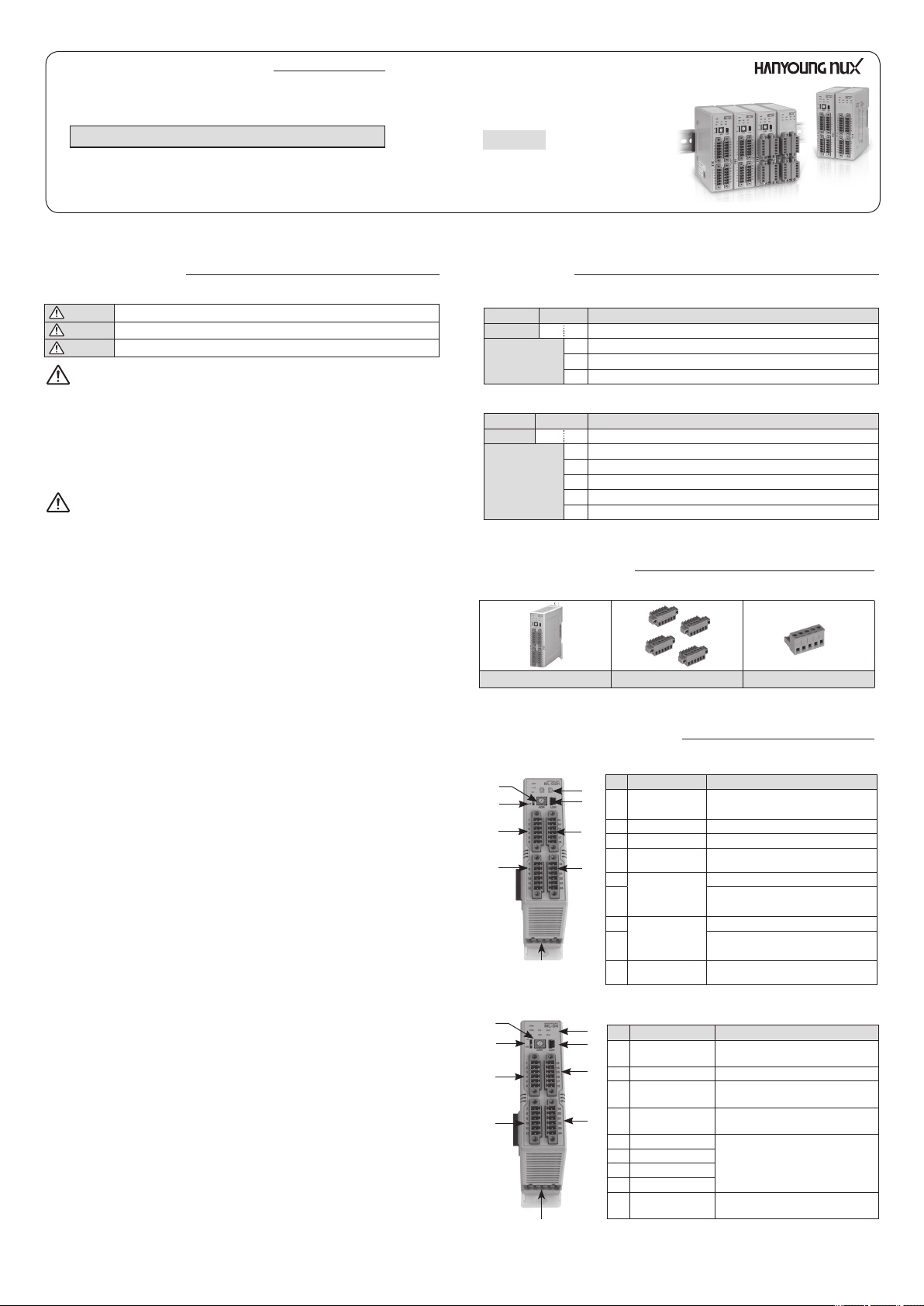
Part names and functions
③
④
⑤
⑥
⑨
③
④
⑤
⑥
.
⑨
3
①
②
⑦
⑧
①
②
⑦
⑧
* When unit expansion address switch is located at +16 and unit address switch
is located at 1 then, RS485 communication address is set up like 1+16=17.
█ ML-D2H
NO Name Function
①
LED status display
②
Loader Jack
③
Unit address switch
Unit expansion
④
address switch
⑤
CH1 Part
⑥
⑦
CH2 Part
⑧
Power and
⑨
communication part
Power, Communication, Event,
Control output display LED
RS232C communication input part
RS485 communication address setting switch (0~15)
RS485 communication expansion address
setting switch (0/+16)*
Temperature input and CT input part
OUT1: Heating control output part
OUT2: Cooling control output part
Temperature input and CT input part
OUT1: Heating control output part
OUT2: Cooling control output part
RS485 communication and 24V DC input part
█ ML-D4
NO Name Function
①
LED status display
②
Loader Jack RS232C communication input part
③
Unit address switch
Unit expansion
④
address switch
⑤
CH1 Part
⑥
CH2 Part
⑦
CH3 Part
⑧
CH4 Part
Power and
⑨
communication part
Power, Communication, Event,
Control output display LED
RS485 communication address
setting switch (0 ~ 15)
RS485 communication expansion address
setting switch (0 / +16)*
Temperature input and
contact output part
RS485 communication and
24 V DC input part
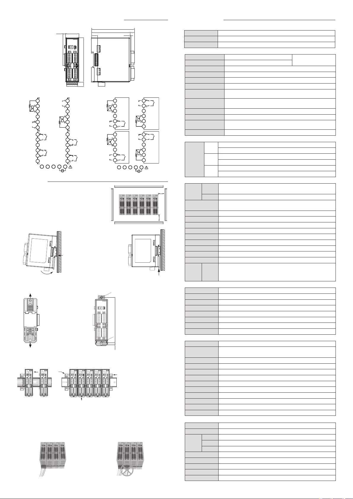
Dimension and connection diagram
96.90
Ø4.20
R2.10
109
ML-D4
PWR
COMEVCH1
CH2
ADR
+0
+16
LDR
CH3
CH4
Ø4.20
30.006.00
PWR
ML-D4
COMEVCH1
CH3
CH2
CH4
+0
+16
ADR
LDR
100.009.70
87.00
█ ML-D2H █ ML-D4
A
1
B
CH1
2
3
B
4
5
CT1
6
7
CH1
SSR1
RLY1
/SCR1
OUT1
8
9
10
CH1
SSR2
RLY2
/SCR2
OUT2
11
12
1
2
+
TRX
TRX-SG
13
CT2
14
15
B
16
B
17
CH2
A
18
19
20
CH2
SSR4
RLY4
/SCR4
OUT2
21
22
23
CH2
SSR3
RLY3
/SCR3
OUT1
24
4 5
3
POWER
24 V d.c.
A
B
B
OUT
A
B
B
OUT
9.90
1.5013.75
1
2
3
CH1
4
RLY
5
SSR
/SCR
6
7
8
9
CH2
10
RLY
11
SSR
/SCR
12
1
2
3
+
TRX
TRX-SG
OUT
B
B
A
OUT
B
B
A
4 5
POWER
13
14
15
16
17
18
19
20
21
22
23
24
24 V d.c
SSR
/SCR
SSR
/SCR
RLY
CH3
RLY
CH4
Installation
•Leave over 100mm space in consideration
of ambient temperature and communication parts'
connector when installing and separating module's
main body.
100
█ Installation by DIN Rail
①
Hang a hook (A) of
the upper back of the
module to the Din Rail
Ⓐ
and install it like (B) by
pressing.
Ⓑ
②
Push mounting
bracket up and check
if it is hanged properly.
█ Installation by screws
①
Find a place for establishment by referring to the size of the left hole
PWR
ML-D4
COMEVCH1
②
Push upper hook and
lower hook on the
bottom of the module to
the outside
CH3
③
CH2
CH4
+0
+16
ADR
LDR
Fix it with M3
screw.
109
R2.10
5.50
█ Installation method of Module
For ML series, it is possible to connect maximum 32 units (including ML-E).
When installing module, install them straight in a vertical orientation.
③
①
Accessing the communication
connector by pushing the
module aside.
②
Confirm that the bottom hook is
locked properly by pressing.
③
Attach stoppers at both ends
of the module in the rail.
█ Power and communication connection
When making one module by connecting many ML series, apply power line and
communication line to only one unit. When making maximum 32 modules, the maximum
necessary power capacity is 224 W (32units X 7W) (Refer to the Power Specification)
<An example of proper way of use> <An example of wrong way of use>
mm
100
Specification
●
Quality
Display range ±0.3% of Input range, ±1 Digit
Insulation resistance Over 500 V DC 20 MΩ (For Power and input part)
Withstand voltage 750 V AC (For power and input part)
●
Input
Thermocouple K, J, E, T, R, B, S, L, N, U, W, PL2
RTD
DC voltage
Pt100Ω, KPt100Ω
0 - 100 mV, 1 - 5 V, 0 - 10 V
Sampling period 50 ms.
Input display resolution
Generally below input range's decimal point
Input impedance Thermocouple and voltage power input : over 1 MΩ
Admissible input
resistance's impact
Admissible input leading
wire resistance
Admissible input voltage
About 0.2 uV/Ω
Thermoresistance
(below 10Ω. but, the resistance of 3 wires should be the same)
within -2 - 5 V (Thermocouple, RTD), within -5 - 12 V (DC voltage)
Input correction ±100% of Input range.
Reference Junction
Complementary Error
Burn-Out Detection
●
Output
RELAY
Control
output
SSR
(ML-D)
SCR
Control
●
ML-D2H
mm
Control
method
ML-D4 2-DOF PID / ON-OFF control
Control operation
±1.5 ℃ (0 ~ 50℃)
105 % of FS (UP-SCALE)
1a contact
250V AC 3A, 30 V DC 3A
Limit to approximately 25mA when shorted more than about 12V (load resistance: over 600Ω)
Time resolution: control period 0.1% or the high part among 10ms
4 - 20 mA DC (Load resistance : lower than 600Ω)
Precision : ±0.1 % of FS (4 - 20 mA range)
PID (Heating/Cooling simultaneous control) /
2 DOF PID (Single control) / ON-OFF control
Selectable between reverse operation (heating) /
direct operation (cooling) (through DR parameter setting)
Proportional band 0 ~ 100 % of FS
Integral time 0 ~ 3,600 Seconds
Derivative time
Cycle time
ON/OFF control
0 ~ 3,600 Seconds
25 ~ 30 seconds (relay control output), 2 ~ 4 seconds (SSR control output)
It is possible to set up when proportional band is 0.
Manual reset It is possible to set up manual reset when integral time is 0 second
Alarm setting range
0 ~ 100% of input range (Absolute alarm), ±100 % of input range (Deviation alarm)
Alarm hysteresis Through EVHY parameter setting
Alarm type Through EVTY parameter setting (18 types)
Heater
Break
Alarm
●
RS232 communication
Communication protocol
Max. communication range
Communication speed
Applicable in ON/OFF control, time proportional control output
(Detection is possible when output ON/OFF time is less than 0.2 seconds.)
ML-D2H
Measuring current: 1 – 5 A AC (resolution: 0.5A ± 5 % of FS ± 1 Digit)
CT model name for Heater break alarm: CT-50N
RS-232 EIA standard
15 m
9600 bps
Start bit 1 bit
Data length 8 bits
Parity bit Even
Stop bit 1 bit
Supported protocol PC-Link
●
RS485 communication
Communication protocol
Number of maximum
connection
Communication method
Max. communication range
Communication process
Communication speed
RS-485 EIA standard
31 units
2 wires half duplex
1200 m
No process
9600, 19200, 38400, 57600, 76800 bps [Initial value : 9600]
Start bit 1 bit
Data length 7, 8 bits [Initial value : 8]
Parity bit None, Odd, Even [Initial value : Even]
Stop bit 1 , 2 bits [Initial value : 1]
Response time Receiving processing time + (response time X 10 ms)
Supported protocol
●
Power supply specification
PC-Link , PC-Link with SUM, Modbus ASCII/RTU [Initial value : PC-Link]
Power voltage 24 V DC
Voltage regulation ±10 % of power voltage.
Below 3W
Consumption
voltage
Ambient temperature
Ambient humidity
System requirements
Storage temperature
ML-E
Below 5W
ML-D4M, ML-D2HMM
Below 7W
ML-D4S, ML-D4C, ML-D2HSM, ML-D2HSS
0 ~ 50 ℃
35 ~ 85 % RH (But, not dew condensation )
Not in a poisonous gas, not in a magnetic filed or in a place where dust is present.
-25 ~ 65 ℃
Weight Approx. 220g (Excludes the packing box)
4
Each channel selected
by INP parameter
 Loading...