

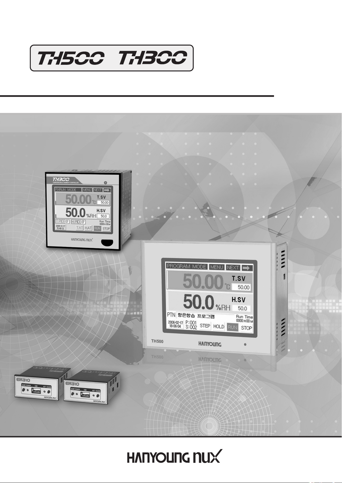
●
Programmable Temperature and Humidity Controller
Manual

tableofcontents
before starting
1
Installation method
2
3 Setting and operating
4 Displays
5 Function setting
1.1 Checking the product5
1.2 Safety information7
.3 Quality guarantee8
1
2.1 How to install9
2.2 Suffix Code10
2.3 Dimension and panel cutout11
.4 Connection diagram14
2
2.5 Communication connection18
3.1 Initial screen20
3.2 How to input21
The name of each part on the operating screen
3.3
3.4 Fix control30
3.5 Program running32
3.6 PID Auto-tuning34
3.7 Graph display and setting35
3.8 Error indication36
4.1 Working display37
4.2 Function setting display38
4.3 System setting screen38
5.1 Operation setting41
5.2 Program setting42
5.3 Date/time reservation setting55
5.4 Graph/Save setting56
26
6 System setting
7 Simple example
8 Specification
6.1 Sensor type setting59
6.2 Control output setting63
6.3 Retransmission output setting66
6.4 Inner signal and alarm setting67
6.5 P.I.D setting71
6.6 Digital input (D.I) configuration setting74
6.7
Digital output (D.O) configuration setting
6.8 Communication setting80
6.9 Other setting81
7.1 Input related setting82
7.2 Output related setting84
7.3 Inner signal setting85
7.4 Fix control86
7.5 Program control88
8.1 Input91
8.2 Output91
8.3 Communication92
8.4 Power supply92
8.5 Functions93
8.6 Touch LCD94
8.7 Operation environment94
76
9 Accessories
(sold separately)
EM310 USB memory storage device95
3

1
Before Starting
Thank you for the purchase of HANYOUNG Temperature and Humidity Controller
(Model# TH500/TH300).
This manual contains the function of product, install method, caution information and the way of using
this controller. So please read this manual before using it. And also please make this manual to be
delivered to the final user and to be placed where can be found and seen easily
(Contents of this user manual can be edited without prior notice for improvement and modification of
the product.)
* Information in this manual may changed without prior notification.
* If you have any question or find error in this manual, please contact us
* Copying or reprinting this manual without notifying us is prohibited.
■ Service(A/S)
* Please send product to the nearest distributor, agency or head quarter for A/S.
When willing to have an on-site A/S, please call our A/S center and make an appointment.
*
* Before making an appointment for A/S, please check out our web and search for the same
problem in our FAQ.
HANYOUNG NUX
#1381-3, Juan-Dong, Nam-ku, Incheon, Korea
TEL : (+82-32) 876-4697
FAX : (+82-32) 876-4696
URL : http://www.hynux.com
E-mail : overseas@hynux.com
4

1.1 Checking the product
After purchasing the product, please check for the correct model type and check for any abnormal
parts/scratches on the outside. If it is incorrect model type or find any abnormal parts/scratches on
the outside, please contact to our nearest sales office.
1.1.1 TH500
⦁ Standard
1)TH500-1NN
Resistance
250 Ω× 2
Standard Type
⦁ Additional
1)TH500-21N
Additional Type
Resistance
250 Ω×2
Fixing bracket
Fixing bracket
40p cable
Manual
I/O Board 1
Manual
5
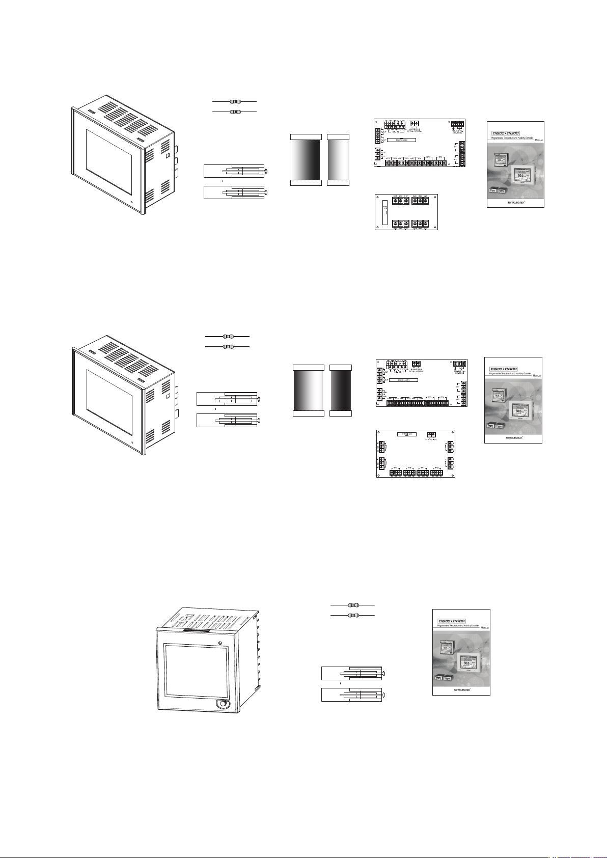
2)TH500-24N
Additional Type
3)TH500-25N
Resistance
250 Ω×2
Fixing bracket
Resistance
250 Ω×2
40p cable
20p cable
I/O Board 1
I/O Board 2
Manual
I/O Board 1
Additional Type
1.1.2 TH300
Fixing bracket
40p cable
20p cable
Resistance
250 Ω×2
Fixing bracket
I/O Board 3
Manual
Manual
6
1.2
Safety information
Alerts declared in the manual are classified to Danger, Warning and Caution by their criticality
Danger
Warning
Caution
DANGER indicates an imminently hazardous situation which, if not avoided, will result in death or serious injury
WARNING indicates a potentially hazardous situation which, if not avoided, could result in death or serious injury
AUTION indicates a potentially hazardous situation which, if not avoided, may result in minor or moderate injury
C
Warning
• For safety and security of the system that is connected to the product, please read and follow
this manual carefully.
• We are not responsible for any damages and safety problems due to disregards of the manual or
lack of care of the product.
• Please install any extra safety circuitry or other safety materials outside the product for safety of
the program that is connected to the product.
• Do not disassemble, repair or reconstruct the product. It can cause electric shock, fire, and errors.
• Since this is not explosion-proof structure, please use in a place where corrosive gas
(such as harmful gas, ammonia, etc.), combustible or explosive gas does not occur.
• Do not give impact to products. It can cause of damage or malfunction.
• When you wire it, please cut out all of electric power.
• Please do not block ventilating windows. It may cause of break down.
•To avoid electric shock, please use it after installation to panel.
• Do not operate controller with wet hand, it may cause of electric shock.
• This controller is operating in 100 V - 240 Va.c, 50 - 60 Hz without additional change.
If you use other voltage, it may case of fire and electric shock.
• When you put to earth, please refer to install method. But do not it earth to gas pipes,
phone lines and lightning rods.
• When installing the product, please install a switch or a circuit break in order to separate the main
power.
Caution
•Please avoid installing the product for following places where
·People can touch terminal unconsciously
·Directly exposed to the mechanical vibration or impact.
·Exposed to the corrosive gas or combustible gas.
·It is exposed to mechanical shock or vibration
·Danger of corrosion or combustion of gas exist
·Temperature changes too frequently
·Temperature is either too high or too low
·It is exposed to direct rays
·It is exposed to electromagnetic waves too much
·Humid place
7

·It has many combustible objects
It has dusts and salinity
·
•The case of this controller is chrome-zinc plating and Bezel is made by ABS/PC
anti-combustion material but please not install it to the inflammable place.
Especially please do not put it on the inflammable products.
• Please keep it away from the machine or wires that can be cause of noise.
Especially, please have enough warn-up when you operate it under 10 Ωtemperature.
•Please install it on horizontally
• Please follow Safety Information to prevent any fire, electric shock and any damage.
• Please follow this manual for install and operation of this controller.
• Please do not turn on power until you install all of parts
• The grade of over voltage is CatalogueII and using environment is DegreeII
1.3 Quality guarantee
•Unless it is included company's conditions for warrantee, we are not responsible
for any warranties or guarantees.
• We are not responsible for any damages and indirect loss of the use or third
person due to unpredicted natural disasters.
• The warranty for this product is valid for 1 year from purchase, and we will fix any
breakdowns and faults from proper uses as it is mentioned in this manual for free.
• After the warranty period, repair will be charged according to our standard policies.
• Under following conditions, repair will be charged even during warranty period.
•Breakdowns due to user's misuses
•Breakdowns due to natural disasters
•Breakdowns due to moving the product after installation.
•Breakdowns due to modification of the product
•Breakdowns due to power troubles
• Please call our customer service for A/S due to breakdowns.
8
Panel
Insertion direction
Thickness of
panel : 1 ~ 10 ㎜
Fixing bracket
Panel
Insertion direction
Thickness of
panel : 1 ~ 10 ㎜
Fixing bracket
Fixing bracket
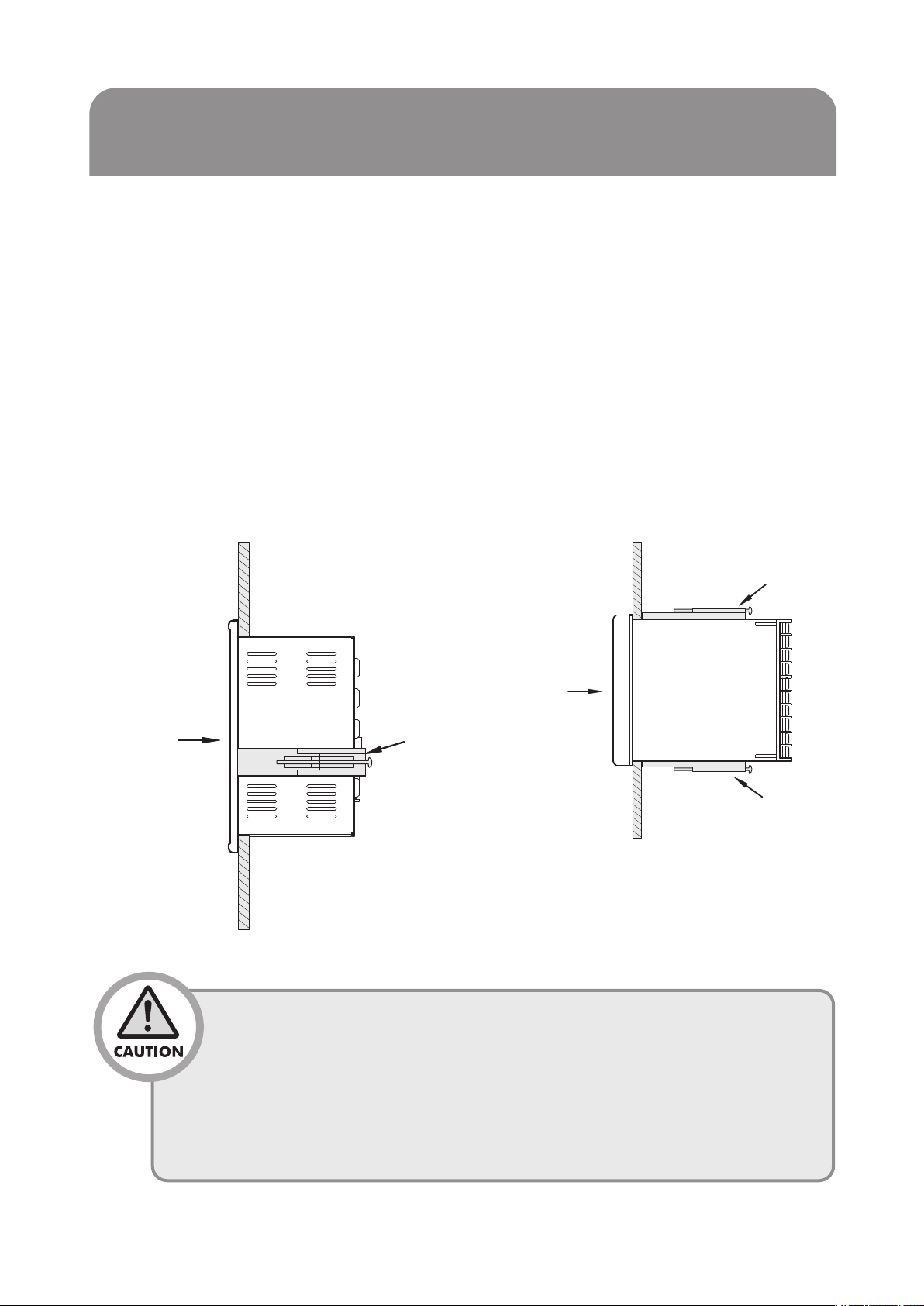
2 Installation method
This is information for installation place and method of TH300/TH500 temperature and humidity
program controller. So please ready it before installation.
2.1 How to install
(1) Use the sheet plate with thickness 1 ㎜ ~ 10 ㎜ for panel
(2) Push in the temperature/humidity controller starting at the front panel
(3) Mount the product by using the fixing bracket just like an image below.
(4) Tightening ittoostronglymay damagethefixingbracket orchangetheshapeofcase
when mounting it to the panel by using the fixing bracket.
■TH500 ■TH300
•To prevent electric shock, please check “turn off power”
•Before turn on power, please connect over the thirdclass grounding.
•During retransmission, it may cause electric shock so please do
not touch terminal.
• Please wire it after turn off main power
• Please contact around 2A fuse to main electronicpower line.
9
2.2 Suffix Code
2.2.1 TH500 Suffix Code
Model
TH500 -
TYPE
Separate Input ·
Output Board
Code
☐☐☐
1
2
N
1
2
Description
Programmable Temp.& Humidity Controller/ 183(W)X144(H)x103(D)
✽ Temp. & Humidity retransmission output
Standard
Type
Additional
Type
No Standard body (In case of purchasing separate I/O Board)
Input·Output Board-1 (Relay output 12 points)
Temp. & Humidity control output(SSR/SCR)
D.I : 8 points, D.O : 12 points Relay Output, SMPS : 24Vd.c18 W
Input·Output Board-2 (Open Collector 8 points external terminal board)
✽ Temp. & Humidity control output(SSR/SCR)
✽ Temp. & Humidity signal input ✽ Digital Input(D.I) : 8 points
✽ Digital Output(D.O) : Relay 12 points, Open Collector : 8 points
✽ Communication : RS232,RS485/422,USB
✽ Separate I/O Board from standard body.
✽ Temp. & Humidity retransmission output
✽ Temp. & Humidity signal input
✽ Communication : RS232,RS485/422
(Option)
3
4
5
N
Language
※ Example of Suffix Code (Standard type : TH500-1NN / Additional type : TH500-21N)
Input·Output Board-3 (Relay output 8 points output board)
Input·Output Board-1 + Output Board-2
Input·Output Board-1 + Output Board-3
No Output Board (In case of selecting standard body)
Korean / English (Standard)
N
English / Simple Chinese
2
English / Traditional Chinese
3
Korean / Simple Chinese
4
Korean / Traditional Chinese
5
2.2.2 TH300 Suffix Code
Model
TH300 -
Communication
Code
☐☐
1
2
Programmable Temp.& Humidity Controller/ 96(W)X96(H)x100(D)
RS232C
RS485/422
Description
Language
1
Korean/English
2
English/Simple Chinese
3
English/Traditional Chinese
10
186 min
147 min
186 min
147 mi n
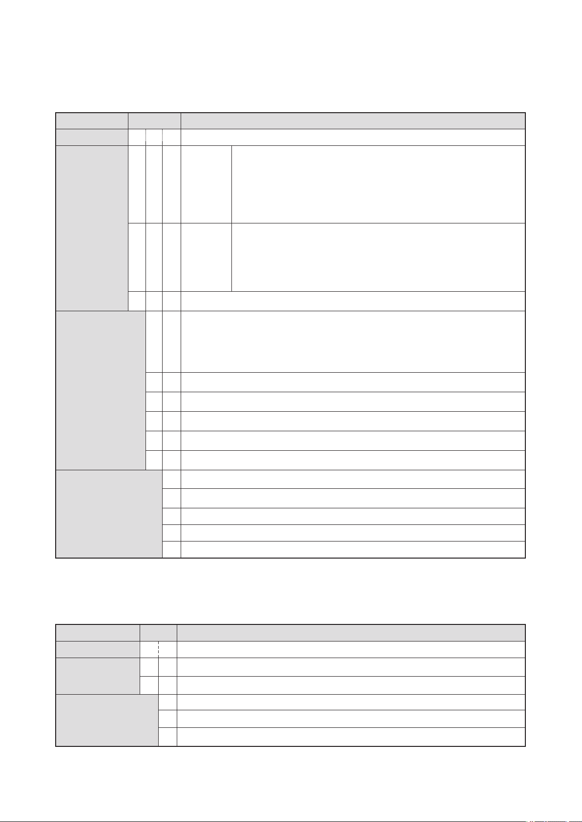
2.3 Dimension and panel cutout
2.3.1. Type
●TH500-1 (Standard)
[Unit : ㎜]
●TH500-2 (Additional )
[Unit : ㎜]
11
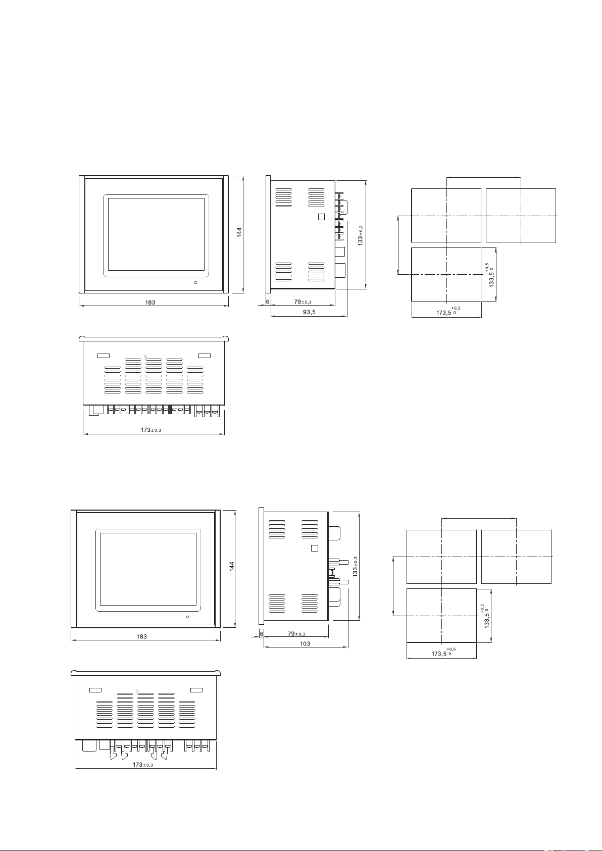
2.3.2 Separate body
Connector(40 Pin)
P
ower Supply for sensor
24 V d.c 18 W max.
D
.I - 8 Points
Connector(20 Pin)
● Input/Output board-1
[Unit : ㎜]
● Output board-2 (External terminal board)
[Unit : ㎜]
12

● Output board-3
Connector(20 Pin)
Unit : ㎜]
[
2.3.3 Standard type(TH300)
[Unit : ㎜]
13
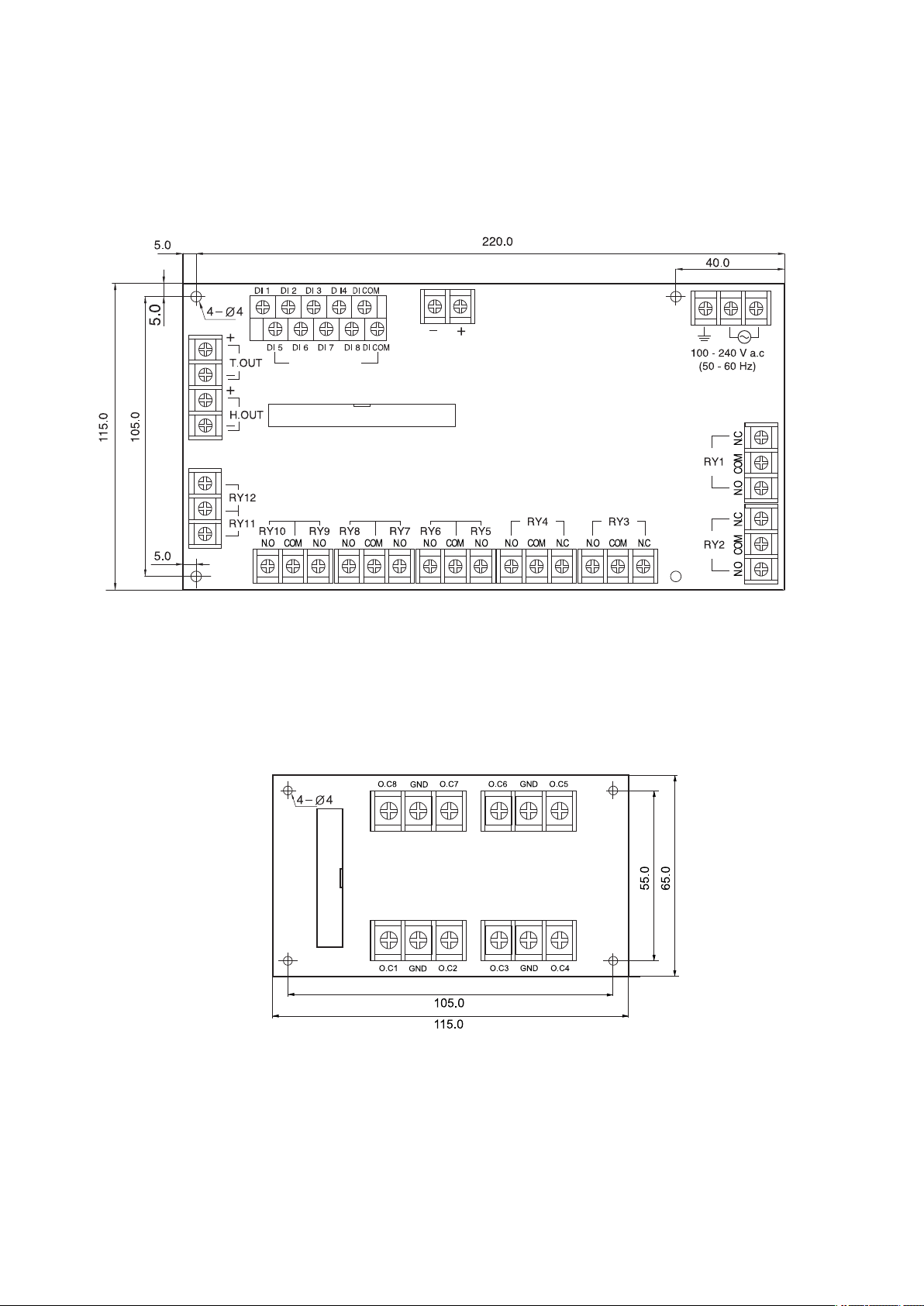
2.4 Connection Diagram
2.4.1 Model : TH500-1☐☐
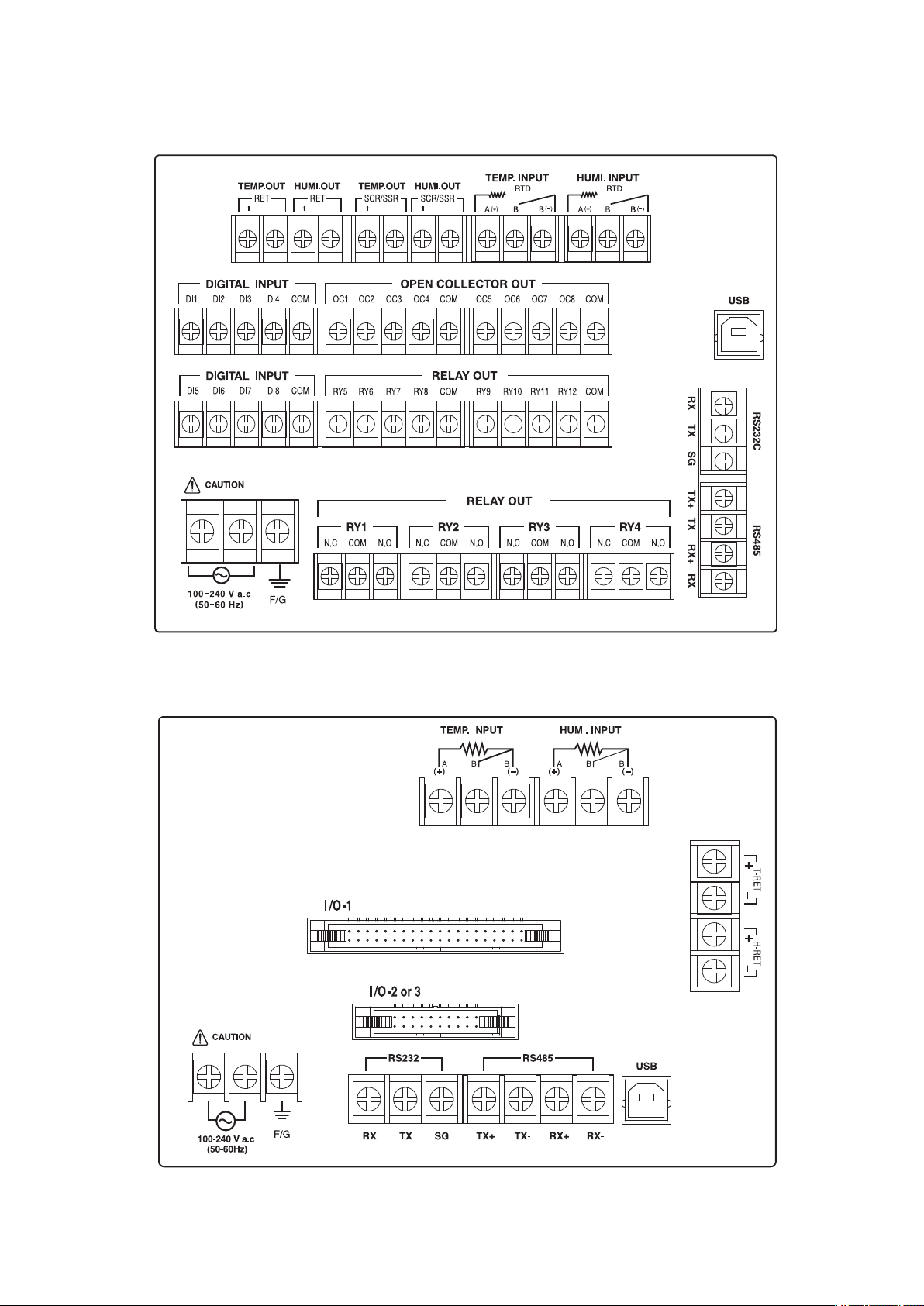
2.4.2 Model : TH500-2☐☐
14
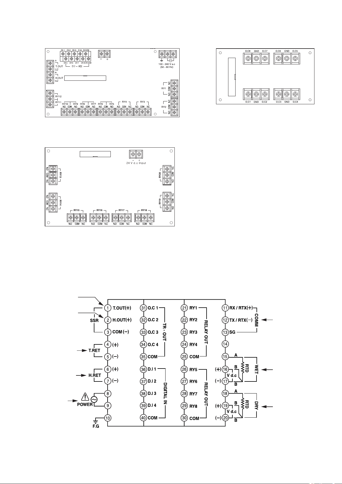
Te m p e r a t u r e
Control output
Humidity
Control output
Te m p e r a t u r e
retransmission out
Humidity
retransmission out
Power
supply voltage
Communication
terminal
Humidity
input sensor
Te m p e r a t u r e
input sensor
Connector(40 Pin)
Power Supply for sensor
24 V d.c 18 W max
Connector(20 Pin)
Connector(20 Pin)
● Input/output board-1
● Out put board-3
● Output board-2
2.4.3 Model : TH300☐☐
15
2.4.4 Connection method
SSR or SCR
r
recorder,
indicator and etc
•Grounding needs more than 2 ㎜ 2 wire at least the 3rd class grounding
connection (Grounding resistance : less than 100 Ω).
•Please use input signal wire and output wire with shield and the shield
needs to have one point grounding.
•In case of R.T.D input, please connect 3 wires without resistance difference
among three wires.
•Please connect Input, Output signal wire separately from power line.
•In case of current input, please attach resistance 250 Ω0.1 % at the end
of input terminals and use it accordingly.
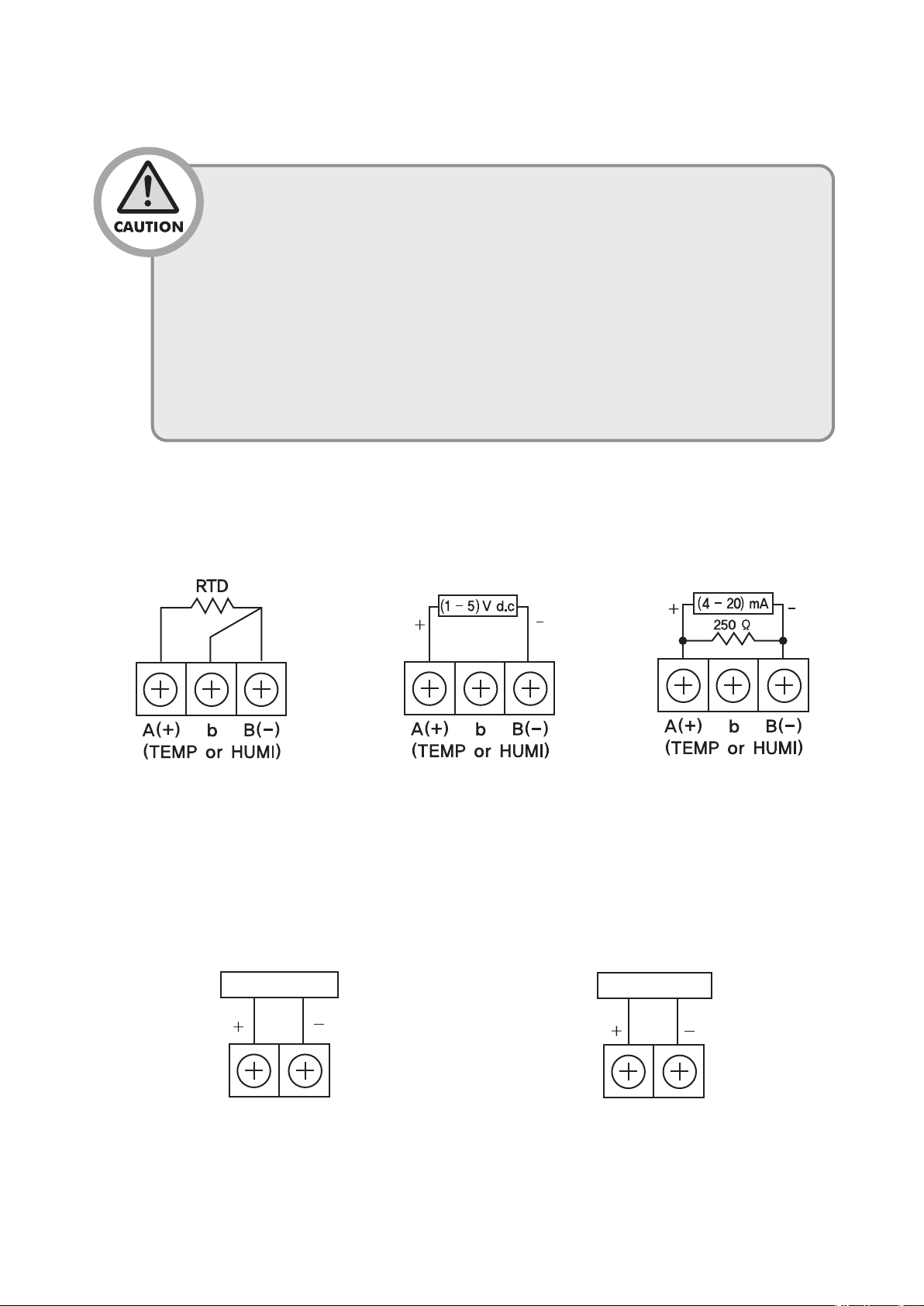
● Sensor Input
■ RTD Input
Connection of Temp / Humidity control output and retransmission output
●
■ Connection of Temp / Humidity control output■ Temp / Humidity retransmission output
■ DC voltage input■ DC current input
16

● Digital output (D.O)
■ Relay output (1c Contact) - ※ Only with TH500.
■ Relay output (1a Contact)
■
Transistor output (With TH300 D.O : 1 ~ 4)
17
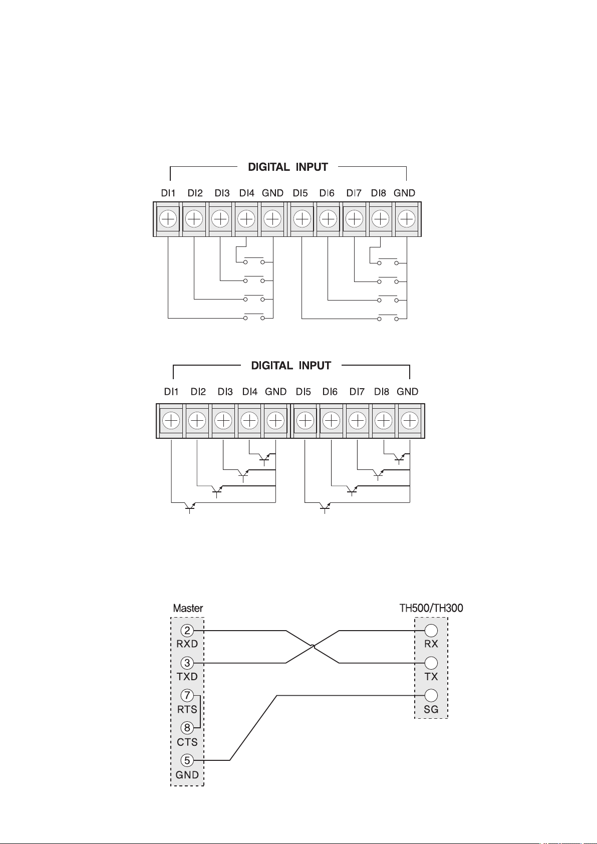
2.4.5 Digital Input (D.I)
When using open collector, please use as follows : Voltage of both ends should be below
2 V and leakage current should be below 100 ㎂.
● Relay input
● Transistor input
(D.I of TH300 D.I : 1 ~ 4)
(D.I of TH300 D.I : 1 ~ 4)
2.5 Communtcation connection
2.5.1 RS232C Connection(base on 9pin connector)
18
Te r mi na ti ng
resistance
Te r mi na ti ng
resistance
T
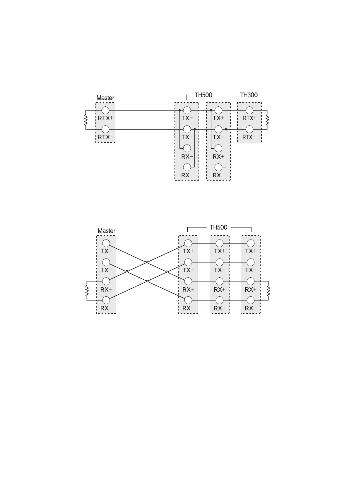
2.5.2 RS422/RS485 arrangement
Te r mi na ti ng
resistance
Te r mi na ti ng
resistance
maximum 32 machines. Please contact Terminating Resistance
100 ~ 200 Ω1/4 W) to the both of ends for retransmission lines.
(
● 2 Wire connection
● 4 Wire connection
19
3.
Setting and Operating
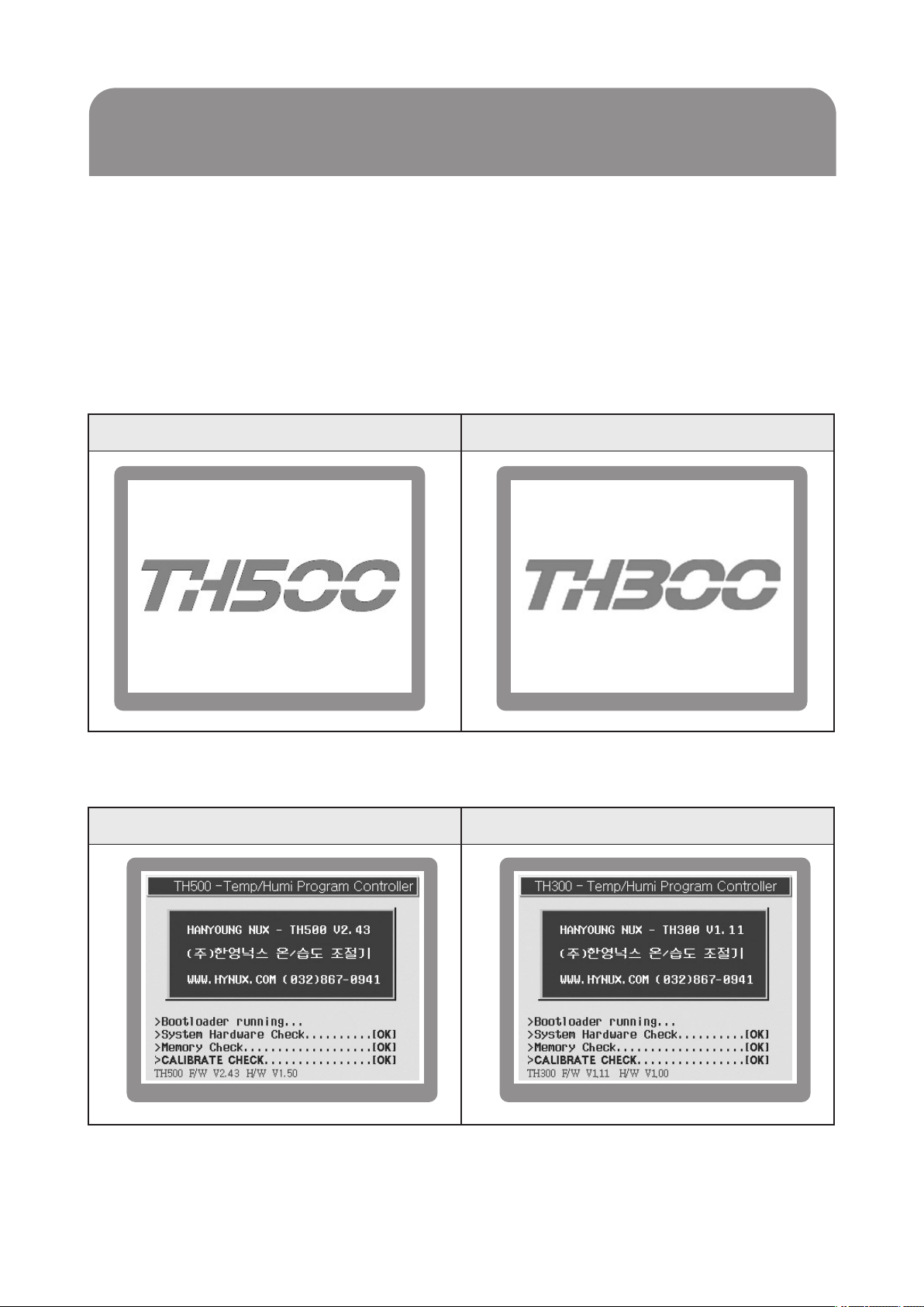
3.1 Initial screen
Whensupplyingthepowerinaftercompletingtheinstallation, operatingscreenwillbe
displayedaftertheLogodisplay[FIG.1) screenandcheck[FIG.2] screenaredisplayed
sequentially. (Users can edit the logo display screen and system check screen)
TH500TH300
[FIG.1] Logo display
TH500TH300
[FIG.2] System check
20

3.2 How to input
Basicsettingbuttonandinputscreenhasthefunctionas[Figure1]. Inputscreenwhichis
able to set necessary data on each screen will be displayed..
⦁ [Figure 1] Setting button and Input screen
Button
Name
Select button
Active input box
(Input vailable)
Inactive input box
(Input unavailable)
Function
Users can select this button on their demand.
If you press this button, its color will turn into another.
By releasing it back, you can select this button operation.
Users can enter various set values into this box as they
wish. When you press the box, a certain range of numbers
or the text input box [Fig.4 to Fig.7] will appear epending on
situations.Then, you have only to press the set value.
This box is inactive under current conditions or situations.
However, if you put it under certain conditions or situations, it will turn
into the active input box as shown above.
3.2.1 Screen for number input
The Fig. 3 is the basic number input box. You can enter integral numbers or real numbers
(decimal point) there. The title of an entered number and its upper and lower limits will be
indicated on the left top of the box. The current input value will be indicated at the indication
box over the figure board. The entered number will be entered completely only if you enter the
key. You can cancel the entered content by pressing the key.
[Fig.3] is the basic number input box
21
3.2.2 Number / Korean / English / sign Input
Fig. 4 to 7 shows the screen for entering the Number/Korean/English/Sign. This multi-input screen
enables you to enter the Number/Korean/English/Sign text respectively by pressing the in
turn. Its shift order is→ → → You can return to the
by pressing theThe arrangements ofNumber/Korean/English/Sign keyboards
are different from each other. However, the Function keys on the right side play the same roles as
follows.
ButtonInformation
Delete all the current texts entered.
Delete one letter ahead of the current cursor.
Savethetextindicateduptothecurrentcursorintothe
internal memory.
After typing the text based on the combination of keys and functions, you can save all
the texts completely by pressing the key. As they save completely, you will be also
escaped from the multi input screen. If you are to cancel the text, you can press thekey
on the right top side. By doing so, you can delete all the current text while escaping the input box.
When pressingin the upper part of initial screen
Program operation setting
displayed. Set up by displaying the input screen of number, Korean, English, and,
symbol with using the
→
Number input screen [Fig.4] is going to be
→→
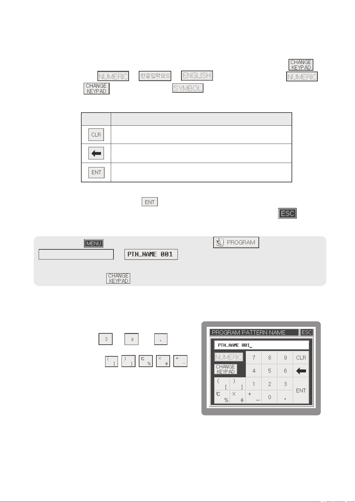
3.2.3 Number Input Mode
The screen for number input is shown in the [Fig.4]. If
you press the number ~ and keys
once, they will be indicated on the cursor position.
Whenever you press the
keys on the left side of the keyboard, they will be
indicated in turn. When you press such duplicate keys,
the cursor will not move at all while waiting for
continuous entry. At that time, if a certain period of time
(approx. 1 second) passes, the cursor will move
automatically to the next position disabling you from
continuous entry.
22
[Fig.4] The screen for number input

Ex) If you want to indicate 1. (The _ on the bottom indicates a flickering cursor.)
Operation:
•
• Result : 1_
Ex) If you want to indicate 123.45. (The _ on the bottom indicates a flickering cursor.)
• Operation: + + + + +
• Result: 123.45_
Ex) If you want to indicate [.
• Operation: + (Press twice within one second.)
• Result: [ _ (The _ on the bottom indicates a flickering cursor.)
• Operation: One second passed after thekey is pressed once.
• Result: [) _ (The _ on the bottom indicates a flickering cursor.)
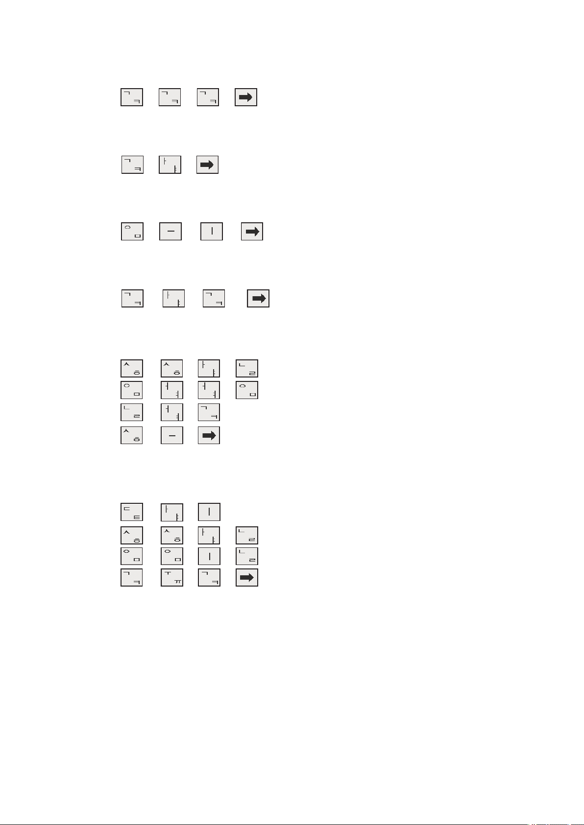
3.2.4 Korean Input Mode
The screen for Korean input is shown on the Fig.
5. All the keys except the,
, keys consist of duplicate keys. There
is also an additional function key . The
principle of using function keys is the same in
every mode. If you want to enter double
consonants such as ㄲ, ㄸ, ㅃ, ㅆ, ㅉ, you should
press the consonant three times. You should press
thekey, if you go to the next letter while
[Fig. 5] The screen for Korean input
entering letters.
Or you can also use such key when entering the blank. The Korean alphabet consists of
three elements such as an initial consonant, a medial vowel and a final consonant. This input
mode is classified into consonants and vowels, so the consonants are not divided into an
initial and final one. Therefore, you have only to enter an appropriate consonant regardless
of its initial or final position. The medial vowel consists of vowels only, so you have only to
press an appropriate vowel.
Ex) If you want to indicate “ㄱ”.
• Operation: +
• Result: ㄱ _ (The _ on the bottom indicates a flickering cursor.)
Ex) If you want to indicate “ㅋ”.
• Operation: + +
• Result: ㅋ _ (The _ on the bottom indicates a flickering cursor.)
23
Ex) If you want to indicate “ㄲ”.
• Operation: + + +
• Result: ㄲ _ (The _ on the bottom indicates a flickering cursor.)
Ex) If you want to indicate “가”.
• Operation: + +
• Result: 가 _ (The _ on the bottom indicates a flickering cursor.)
Ex) If you want to indicate “의”.
• Operation: + + +
• Result: 의 _ (The _ on the bottom indicates a flickering cursor.)
Ex) If you want to indicate “각”.
• Operation: + + +
• Result: 각 _ (The _ on the bottom indicates a flickering cursor.)
Ex) If you want to indicate “한영넉스”.
• Operation: + + + +
+ +++
+ + +
+ +
• Result: 한영넉스 _ (The _ on the bottom indicates a flickering cursor.)
Ex) If you want to indicate “대한민국”.
• Operation: + + +
+ + + +
+ + + +
+ + +
• Result: 대한민국 _ (The _ on the bottom indicates a flickering cursor.)
24
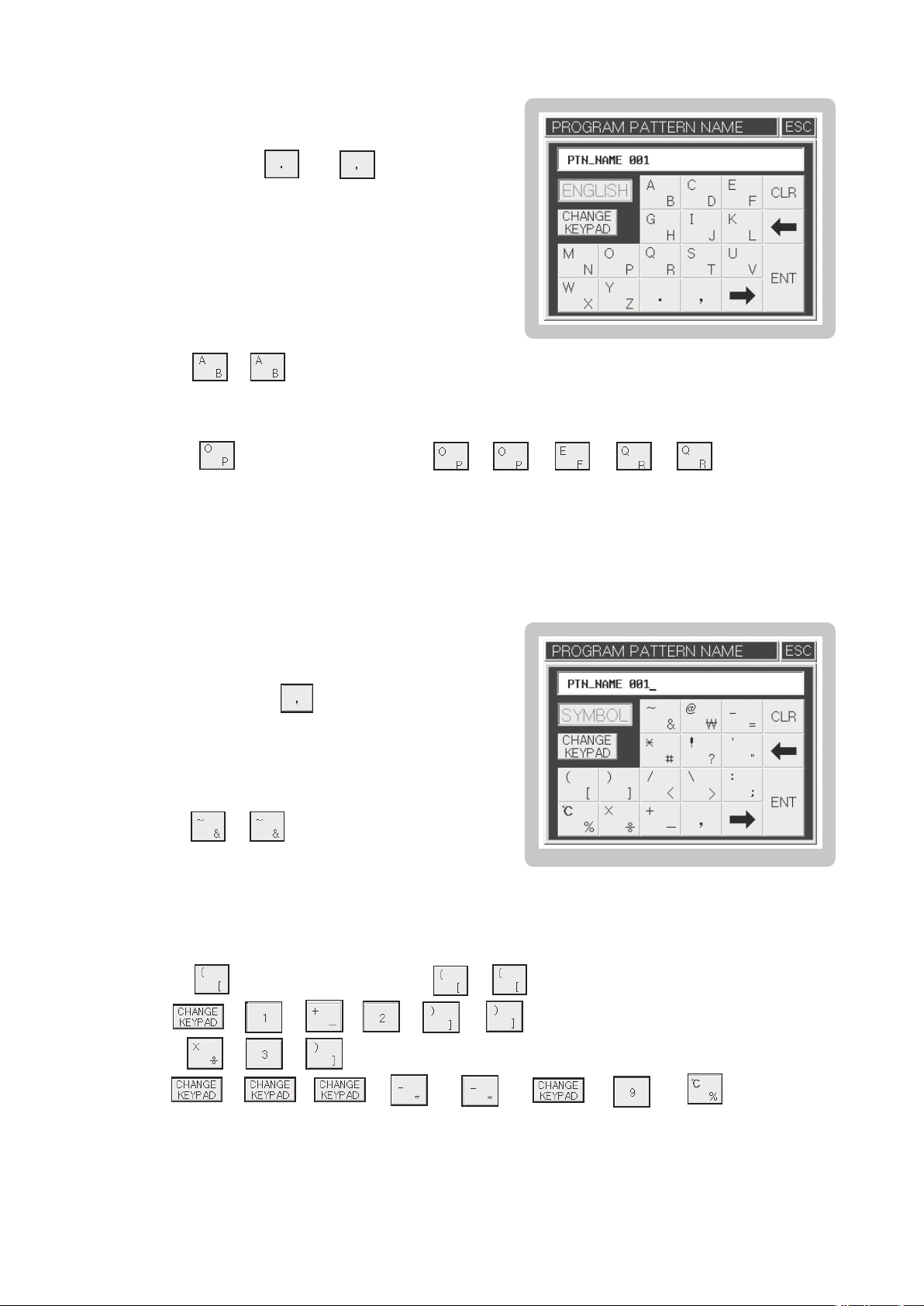
3.2.5 English Input Mode
he screen for English input is shown on the Fig. 6.
T
All the keys except the andkeys consist
of duplicate keys. Its basic use is the same as that
of the Korean input mode.
Ex) If you want to indicate “B”.
• Operation: +
• Result: B _ (The _ on the bottom indicates a flickering cursor.)
Ex) If you want to indicate “OPER”
• Operation: + Waif for one second + + + + +
• Result: OPER _ (The _ on the bottom indicates a flickering cursor.)
[Fig. 6] The screen for English input
3.2.6 Sign Input Mode
The screen for sign input is shown on the Fig. 7.
All the keys except the key onsist of duplicate
keys. Its basic use is the same as that of the
English input mode.
Ex) If you want to indicate “&”.
• Operation: +
• Result: & _ (The _ on the bottom indicates
a flickering cursor.)
Ex) If you want to indicate “([1+2] X 3) = 9 ℃.
• Operation: + Wait for one second + +
+ + + + + +
+ + +
[Fig. 7] The screen for sign input
+ + + + + + + +
• Result: ([1 + 2] X 3) = 9 ℃ _ (The _ on the bottom indicates a flickering cursor.)
25
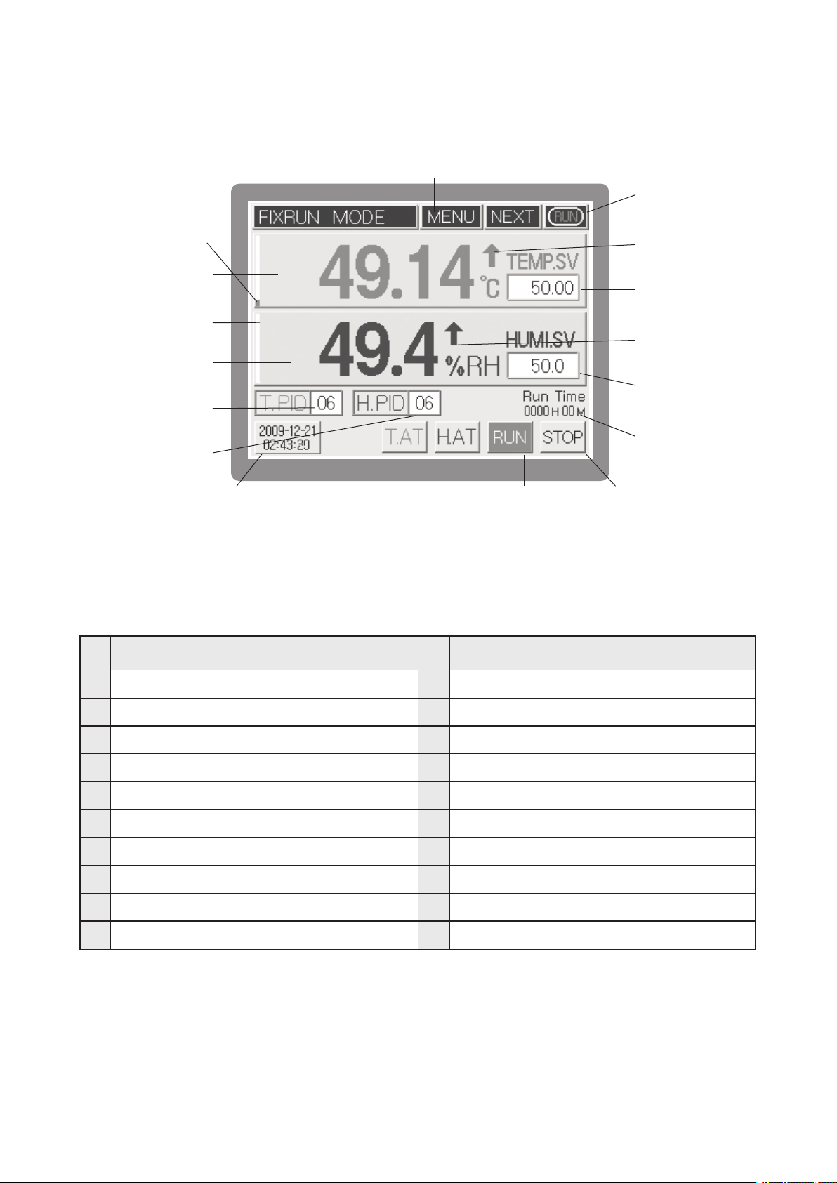
3.3 The name of each part on the operating screen
①
⑤
⑥
⑦
⑧
⑨
⑩
⑪⑰ ⑱ ⑲ ⑳
[Fig. 8] Operation screen 1 for fixed control
②
③
④
⑫
⑬
⑭
⑮
⑯
NO
Current operation status
①
Menu button
②
Operation screen 2 shift button
③
Running/Stop indication
④
Control output BAR for current temperature (MV)
⑤
Current temperature PV
⑥
Control output BAR for current humidity (MV)
⑦
Current humidity PV
⑧
⑨
Temperature PID Zone No. input box
⑩
Humidity PID Zone No. input box
NameName
NO
Current date/time
⑪
Temperature PV Up/Down indication
⑫
Temperature SV input box
⑬
Humidity PV Up/ Down indication
⑭
Humidity SV input box
⑮
Running time indication
⑯
Temperature A/T button
⑰
Humidity A/T button
⑱
⑲
Start button for Fix-Running
⑳
Stop button for Fix-Running
26
⑤
⑥
⑦
⑧
⑨
⑩
① ② ③
④
⑪
⑫
⑬
⑭
⑮
⑯ ⑰ ⑱ ⑲ ⑳ ㉑
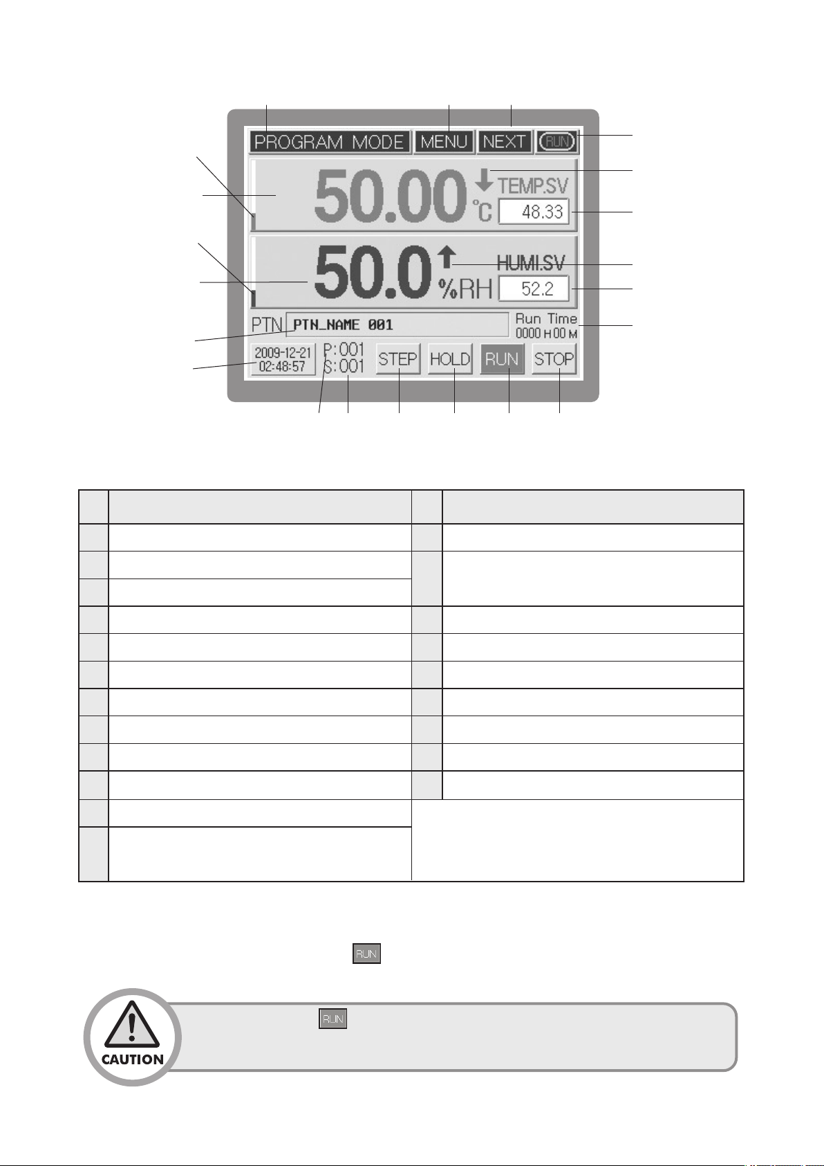
[Fig. 9] Operation screen 1 for program control
NO
Current operation status
①
Menu button
②
NameName
NO
Humidity SV Up/Down indication
⑬
Start segment No. input box (When operation stops, it
⑭
Operation screen 2 shift button
③
Running/Stop indication
④
Control output BAR for current temperature (MV)
⑤
Current temperature PV
⑥
⑦
Control output BAR for current humidity (MV)
⑧
Current humidity PV
⑨
Operation pattern name
⑩
Current date/time
⑪
Temperature SV Up/Down indication
starts within the pattern (segment input unit))
⑮
Running time indication
⑯
Current operating pattern No.
⑰
Current operating segment No.
⑱
Program STEP button
⑲
Program HOLD button
⑳
Program operation Start button
㉑
Program operation End button
※ (16)~(19) displayed only during
Start pattern No. input box(When operation stops, it either
⑫
operation
display the pattern number or used as input unit.)
The operation screen 1 [Fig. 8, Fig. 9] is the basic screen where you can enter either temperature &
humidity setting value (SV) or start pattern/loop No. in the Fix/Program mode. After entering your
desired setting value, you can press thebutton to start controlling.
After pressing the button, you are unable to press various setting buttons
like MENU or input boxes, because they may have a serious effect on system
controlling operations.
27
①
③
②
④
NO
⑤
⑥
⑦
⑧
⑨
⑩
⑪
⑫
⑬
⑯
⑰
⑱
⑲
⑳
㉑
㉒
㉓
㉔
⑭
㉕㉖㉗⑮
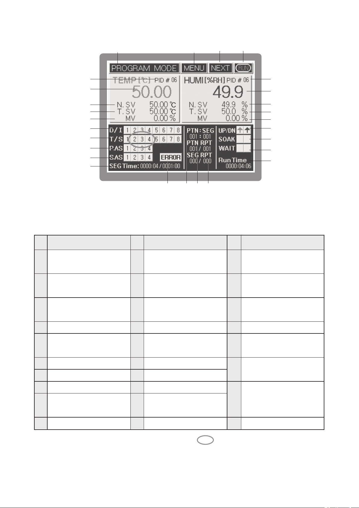
[Fig.10] Operation screen 2 for program control
NameNameName
NONO
①
Current operation status
②
Menu button
Operation screen 3
③
shift button 1
Running/Stop indication
④
Temperature PID ZONE
⑤
No.
Current temperature PV
⑥
Current temperature SV
⑦
Target Temperature Set Value(TSV)
⑧
Controlling output amount of
⑨
current temperature (MV)
D/I status indication
⑩
T/S status indication
⑪
I/S status indication
*
Pattern Alarm Status Indication
⑫
T.ON, H.ON status indication
*
System Alarm Status Indication
⑬
* Delay (D/S)/multiplication (DR)
signal status indication
SEG operation time indication
⑭
System error indication
⑮
button
Humidity PID zone number
⑯
Current humidity process value (PV)
⑰
Current humidity set value (SV)
⑱
Target humidity set value
⑲
(TSV)
⑳
Currenthumiditycontroloutputamount(MV)
Temperature/humidity up/down
㉑
interval indication
Temperature/humidity
㉒
maintain indication
Temperature/humidity
㉓
standby (Wait) indication
㉔
Total operation time (Run time)
Pattern number/segment
㉕
number indication
Pattern repetition indication, Number of
㉖
sequence,/Number of repetition setting
Segment repetition indication,
Number of sequence, /
㉗
Number of repetition setting
※ *Displaying items are displayed when pressing the ( ) which located on the
left-bottom of the screen.
28
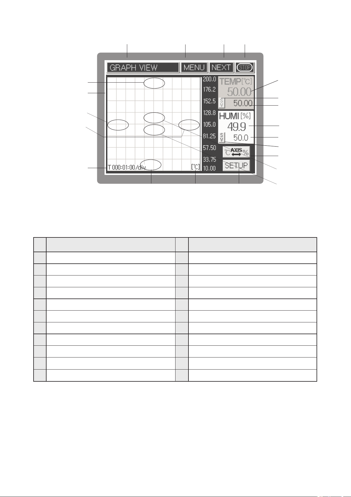
①②③
④
NO
⑤
⑥
⑦
⑧
⑨
⑩
⑲ ⑱
[Fig.11] Screen for graph indication
NameName
NO
⑪
⑫
⑬
⑭
⑮
⑯
⑰
⑳
㉑
Current operation status
①
Menu button
②
Operation screen 1 shift button
③
Running/Stop indication
④
Upside screen of Y axis
⑤
Temperature & humidity SV, PV indication
⑥
Div time increase of X axis
⑦
⑧
Div time decrease of X axis
⑨
X axis time / Div
⑩
Low part screen of Y axis
⑪
Current temperature PV indication
Current temperature MV/SV indicatorshift button
⑫
Current temperature MV or SV indication
⑬
Current humidity PV indication
⑭
Current humidity MV or SV indication
⑮
Current humidity MV/SV indicator shift button
⑯
Y axis temperature & humidity unit shift button
⑰
Y axis unit indication
⑱
Graph/Save setting button
⑲
⑳
Screen ZOOM IN
㉑
Screen ZOOM OUT
29
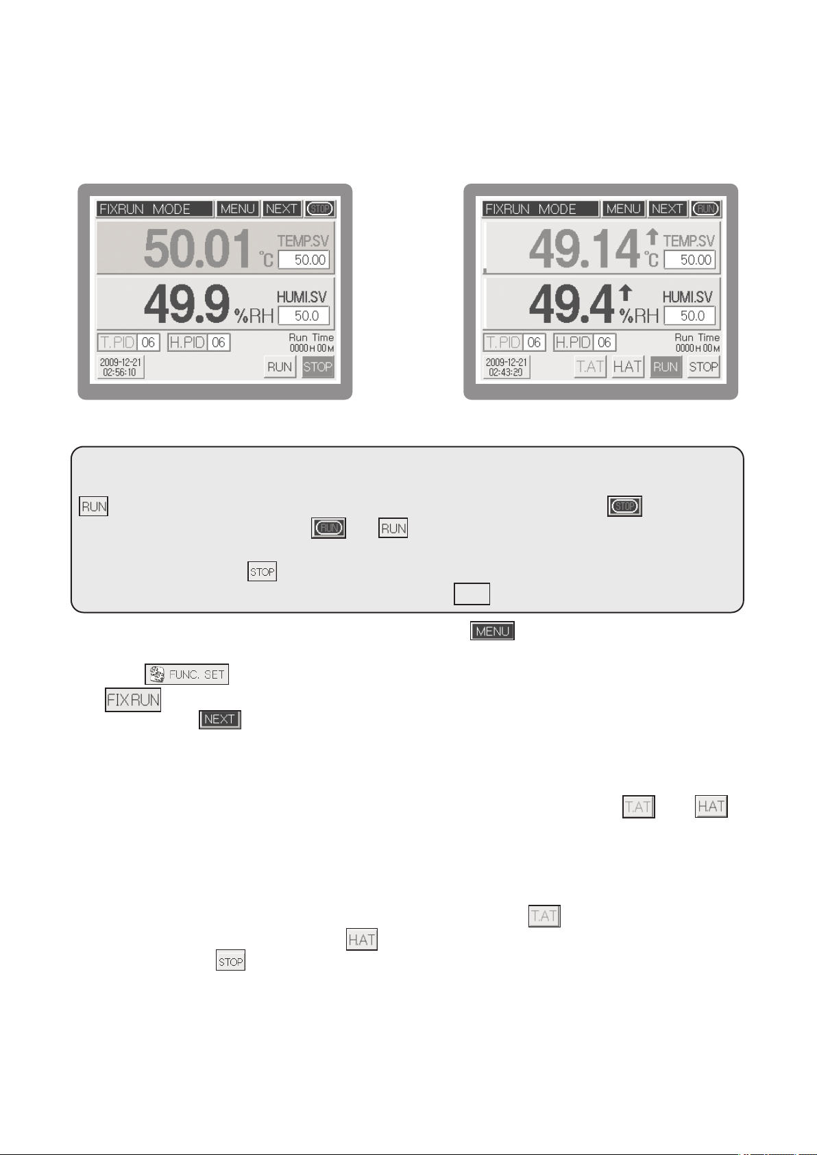
3.4 Running of Fix-control
ix-control is running a temperature and humidity by fixed set value (SV).
F
3.4.1 Running selection of Fix-control 1.
[Fig.12] Running stopped screen 1 for Fix control
Operation start: [FIG.12] Input the temperature set value (temperature SV) and humidity set value
(humidity SV) within the fix control operation stop status screen and press the
button then the fix control operation will be started just like a[FIG.13]. Here, button on the
upper right side will be changed toandbutton on the lower right side will be displayed
with the red color.
Operation stop: Press the button on the lower right side to stop the operation.
("Stop the system control" will be displayed). Here, press to stop the operation
When selecting the fix control or program control, press the button within the fix control
operation stop [FIG12] screen then function setting screen will be displayed. Within this screen,
press the button to select the operation method of function setup 1 screen. Pressing
thebutton will select the fix control. Set each of setting lists in the operation setting screen
2 by pressing the button.
While performing the fix control, changing the set value (SV) will automatically change the PID ZONE
applying number in accordance with the set value. If users want to use the specific PID zone,
please input the PID zone number after inputting the set value. During operation, if and
button appear on the lower side of fix control operation screen, each of these refers to temperature
and humidity auto tuning button. Auto-tuning is operated only in the fix control operation mode and
it runs the auto-tuning by pressing the button after inputting the temperature and humidity set value.
[Fig.13] Running screen 1 for Fix control
YES
In case where users need to stop the auto-tuning, please press the
(temperature side auto-tuning button) or (humidity auto-tuning button). Obviously pressing the
fix control button will the control operation and auto-tuning.
During auto-tuning, all of the computing values corresponding to the auto-tuning will not be saved
if users stop the auto-tuning while it is operating. Auto-tuning can be operated up to 24 hours and
elapsing the indicated hours will stop the auto-tuning.
30
• Whenitcomestotemperature, itsPVwillbealwaysdisplayedunlessthesensor
lineisdisconnected. However, asfarashumidityisconcerned, itsPVwillnot be
indicatedunlessasettingvalue(SV) isentered. Ifyouset theSV to0 andpress
thebutton, you can control the temperature only.
• It is impossible to execute A/T for temperature and humidity at the same time.
Therefore, it is desirable to try tuning humidity while maintaining a target temperature.
The button concerned will turn on and off during tuning.
Auto Tuning button : When pressingbutton in the running screen of Fixing Control, function
setting menu will be displayed. After pressingleft-top button and pressing password, System Setup
screen will be displayed, Once again if you press [Sensor Input Setup], Sensor Input Setup screen 1
will be displayed. Press button and Auto Tuning will be shown on A/T button indication in the
Sensor Input Setup 4.
Temperature Auto Tuning button (Turn on and off during running)
Humidity Auto Tuning button (Turn on and off during running)
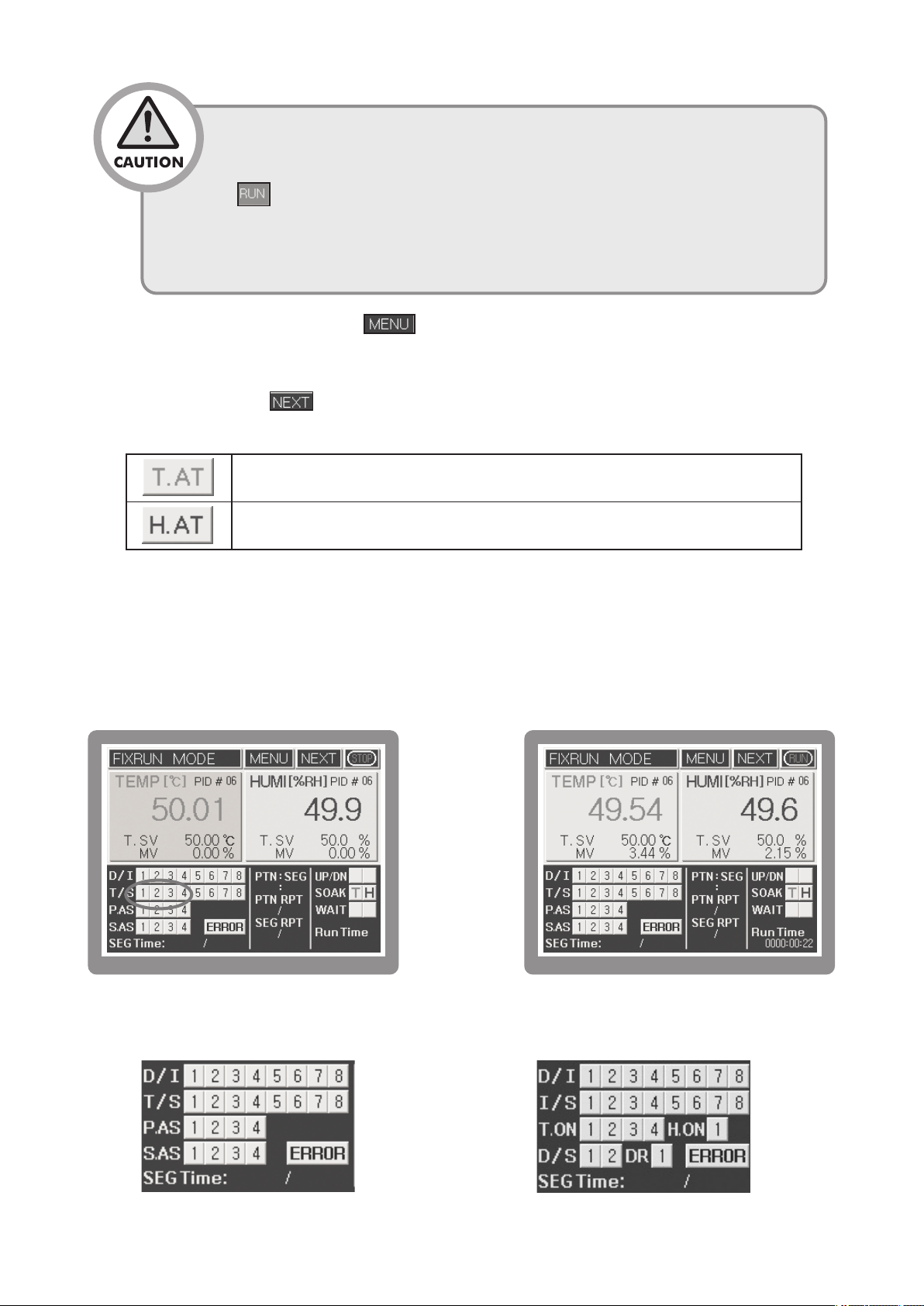
3.4.2 Running selection of Fix-control 2.
Process value and Set value of temperature and humidity is shown basically in the running screen 2
for fix control. There is shown also for Inner signal(I/S), Time signal(T/S), Digital input signal(D/I),
Alarm signal(A/S), and indicate a gradient of initial set value by form of UP/DN and SOAK.
[Fig.14] Running stopped screen 2 for Fix control.
※ Pressing the indicated circle in the [Fig.14] will change the display unit
[Fig.15] Running screen 2 for Fix control
➡
31

3.5 Running of Program control
Program control is control a Process Value (PV) by change of Set Value (SV) according to
course of time.For example, it is increase the current temperature to 30 ℃ for 10 min. and
maintain the 30 ℃ for 15 min., and then increase to 70 ℃ again for 40 min. and maintain the
70 ℃ for 1 hour. Program control is especially using widely in the test equipment for
environment like as thermostat and electric furnace.
3.5.1 Selection of Program Control Running.
[Fig.16] Running stopped screen 1 for program control.
In order to running with program control, press the button of the top on the running
stopped screen 1 for program control [Fig.16] and move to the screen for function setting
[Fig.17].
TH500TH300
[FIG.17] Function setting menu
32

Move to the screen for
“Function setup 1”
with press the
button, and select the program control as running method with press the
button. After finish to setting for function setup 1 ~ 2 with press thebutton, and move
to “Function setting menu” screen with press thebutton. And then, finish the set for
, , and move to the Program Set Screen [Fig.18]
3.5.2 Set of Program Control Pattern
Press the button in the program set screen [Fig.18] and move to the screen for program
pattern set [Fig.19]. Establish the set item for each segment of pattern in the screen for program
pattern set [Fig.19].
[Fig.18] Program Set Screen
Move to the running stopped screen 1 for program control after input for all, and input a start
segment No. in the pattern and program start pattern. And then, program control will be running if
you press the button.
[Fig.20] Running stopped screen
1 for program control.
[Fig.19] Pattern Set Screen
[Fig.21] Running screen 1 for
program control
33

Once the program operation starts, and buttons will appear newly like as running
P
ID auto-tuning interval
AT end
AT start
ON/OFF operation
PID Control interval
creen 1 for program control [Fig.21]. These buttons has function which is related to progress of
s
segment.
Button
It stops the currently processing operation of segment and runs the
next segment operation. Pressing the STOP button on the wait status
or hold status will cancel the hold function and runs the next segment
of current segment immediately.
Pressing the button while it is operating will keep the set value
(set value which had been set right before performing HOLD function)
disregarding the set time. Pressing the button on the hold
status will cancel the hold function and runs the program. While it is
in hold status, pressing the STEP button will cancel the hold status,
skip current segment and run next segment immediately.
3.6 PID Auto Tuning
Auto Tuning (hereinafter referred to as A/T) is the
automatic setting function in which the controller
Function
measures the characteristics of the control system
automatically and calculates the optimal PID values
accordingly. The A/T method measures and calculates
a cycle by producing the ON/OFF control output for the
two cycles and generating the limit cycle of controlled
targets.
You can execute A/T all the time by entering a target
setting value (SV) in the fixed control mode, pressing
thebutton, and pressing the subsequent either
orbutton. After A/T is finished normally, if
the unit is set to automatic PID ZONE reference mode,
the resulted PID value will be saved into the
appropriate PID ZONE. If this unit is set to manual PID
ZONE reference mode, the results PID value will be
saved into your designated PID ZONE.
[Fig 22] PID Auto Tuning
34

•
If A/Tstill runsin 24 hoursafterA/T execution, A/Toperationwill cometoan
end automatically. If you close theA/T operation by force during A/T process,
theoperatingvaluewillnotbesavedandmaintainedasaprevioussetting
value.
3.7 Graph display and setting
Graph's displayscreen is ascreentodisplaythesettingvalueandmeasuredvalueoftemperatureandhumidity.
Inthe graphsettingscreen, Xaxis's time andYaxis's maximumand minimum rangecanbeset upbypushing
eachofbuttonsand setupsaving operationstatusbyselecting ( ),
saveperiod (seconds), andstoringmedium( )
Inthe Yaxis's displayrange, temperature rangeorhumidityrangecanbedisplayed by selectingY button.
[Fig.23] Screen for fix control graph display
[Fig.25] Graph set screen
[Fig.24] Screen for program control graph display
35

3.8 Error Indication
Running screen 2 for program control or fix control [Fifg.26] is indicating an operating state for running.
[Fig.26] Running screen 2 for fix control
The indication of errors through sensor disconnection and external D/I is displayed withbutton
on and off in the running screen 2 for program control [Fig. 26]. If you press the button, the
error occurrence screen will appear. In this case, the error indicator for temperature & humidity
disconnection will appear, while D/I(External contact input) no. 1 to 8 will be displayed on the bottom.
You can check it by pressing the , arrow button.
Press the button to show the operating record indication screen which can check the state of
RUNNING, STOP, Sensor Disconnection and External Contact Input (D/I).
[Fig.27] Indication screen for occurrence of error
[Fig.28] Operating Rec
Whentemperatureorhumiditysensorisdisconnected, controloperation
will be stopped afterpassingsensordisconnection waiting time which was
set in the SYSTEM SETTING.
36

4 Displays
Entire displays are mainly composed of three sections which are Working display, Function setting
display(included In program installation) and System setting display.
4.1
After you finish to connect & turn on the power, Logo signal & System check display will be shown in a moment, and
then Working display will be shown. In that time, according to selecting the initial setting program or Fixed driving
method, it will be shown to Program control working display or Fixed control working display.
Operating screen
[Fig. 29]Program control the 1st working screen
[Fig. 30]Fixed control the 1st working screen
[Fig. 31]Program control the 2nd working screen[Fig. 32]Fixed control the 2nd working screen
[Fig. 33]Program control Graph screen[Fig. 34]Fixed control Graph screen
37

4.2
After you push button in working display condition, Function setting menu screenis shown.
It is composed of 6 buttons. Push each button to set up under an item.
Function setting display
[Fig. 35] Program control the 1st stop screen
TH500TH300
[Fig. 36] Function setting menu screen
4.3 System Setting screen
As pushingbutton in Working display condition, Function setting menu screen is shown.
Pushing the character of Function setting in that time, Password input display is shown. Pushing
after inputting (initial value: 0), the display of System setting function menu shows. It is
composed of 8 buttons.
38

[Fig.37] Password input screen[Fig.38] System setting menu screen
There is no need for System setting made separately by driver. Because the
Basic setting condition of this system’smodel is set up by the operator, you
should be careful especially .
39

5 Function setting
After finishing installation & connection, turn on the power. Logo display & System check display are
shown one after other. and then [Fig.39]fix control the 1st working stop screen is displayed.
[Fig.39] Fix control the 1st working stop screen
Function setting
menu botton
TH500TH300
[Fig.40] Function setting menu screen
InformationInformation
Running Screen will be
displayed.
Function setting
menu botton
Enter into Graph screen.
Running (Operation) Setting
screen will be displayed.
Program Setting(Pattern, Time Signal
setting etc.) screen will be displayed.
Enter into axis X,Y and storage
screen.
Enter into Date/Time
Reservation Setting screen.
40

5.1 Operation setting
5.1.1 Function setup 1
Pushingbutton in [Fig.40]Function setting menu screen, you should select or set
up each setting item of the function setup 1. Choose between Select Program control and Fixed
control in selecting Working method.
[Fig.41] Function setup 1 screen
RUN MODE
T.SV RATE
H.SV RATE
Fix RUN TIME
ZN. TRACKING
PROGRAM
FIX RUN
Set it up as the gradient of temperature variations [℃/m] per hour (minute) from
current temperature to setting temperature in fixed control.
Set it up as the gradient of temperature variations [℃/m] per hour (minute) from
current temperature to setting temperature in fixed control.
After executing the fixed-mode control for the time entered, the operation will stop automatically.
It prevents rapid output change when P.I.D ZONE is changed.
Select in program control
Select in fixed control
5.1.2 Function setup 2
After finishing the setting of Function setup 1, pressbutton to set up the setting item of Function setup 2.
In case outage occurs in working, it will be different with Operation condition in recovering outage by selecting
BOOT RUN of Function setup 2 screen. (only the power recovers within five seconds after outage, the same
condition as before will be kept up.
[Fig.42] Function setup 2 screen
41

FUZZY
FUNC
BOOT RUN
BEEP
t happens that measurement value is more than setting value in initial
I
ver Shoot, select Fuzzy control.
O
According to the load controlling Over shoot, the rising time can be delayed or
Under Shoot can become larger in some cases.
Program control
STOP
COLD
HOT
Turn on/off the buzzer sound to check various input and operation.
Start to operate again from the beginning
Start to operate from segment before outage
STOP
Start running in accordance with
the set value before outage.
Fixed control
STOP
TOUCH PNL.
SCREEN
P.DOWN
It is used to limit the touch panel input during system control operating. Selecting Lock, it is
impossible to input except , and/ buttons.
As it is the function to turn off the power of Back-Light after the setting time in order to
protect the LCD display, it can set up Setting time as a unit per a minute. Setting 0 when it is
not used, it is turning on all the time.
5.1.3 Function setup 3
After finishing Function Setup 2, please touch button to display Function Setup 3 screen.
You can adjust LCD brightness by, button in the Function Setup 3.
[Fig.43] Function setup 3 screen
5.2 Program setting
Press button in Function setting menu screen[Fig. 44] Program setup menu will be
shown. It is composed of 5 buttons. Push each button to set up under an item.
42

TH500TH300
[Fig.44] Function setting menu screen
[Fig.45] Program setup menu screen
5.2.1 Pattern setting
Pushing button in program setup menu screen[Fig. 45] Program pattern setup screen is indicated.
Set the agreeable segment of each pattern in this screen.
Program control will process according to the content & sequence of segment designed.
[Fig.46] Program pattern setup screen[Fig.47] Segment selection screen
43

⦁ Setting each input item of [Fig.45] in reference of the diagram below.
Name
nter the pattern number [ ] to set or select it by pressing
PTN NO.
SEG.Page
TEMP. SV
HUMI. SV
Hour/Min
Wait
T.S.(Time Signal)
ALARM
⦁ SEG. Insert/Delete
Pressing SEG number in the left side of [Fig.46], it is shown in red to segment moved & selected into
SEG. Insert/Delete display.
SEG. Page button is changed into, button in that time. Pressing this button, Segment should
E
the/ button.
Pressing the/ button, it moves each 4 segment.
Pressing the setting window, set Temperature SV of segment.
Pressing the setting window, set Humidity SV of segment.
Setting operation time of segment.
Selecting waiting operation function set in waiting operation setting display.
Selecting valid time signal in segment.
Selecting each action among 4 kinds of signal esigned in pattern signal
setting display.[Fig.47]Pattern signal selection screen
Function
-100~200 ℃ TH500
-100~500℃TH300
0 hour ~ 255 hour 59 minute
ange
R
1 ~ 100 Pattern
0.0 ~ 100.0 %
ON/OFF
1 ~ 4 each
ON/OFF
be inserted or deleted and then the next Segment will be moved.
⦁ Waiting/Pattern signal selection
Select Waiting, Pattern signal item of Program pattern
setting display to execute contents set in Waiting
Operation Setting display & Pattern Alarm Setting
display (If you press button in Program
setting display, Waiting Operation Setting display will
be indicated.)
[Fig.48]Pattern Alarmselecting screen
5.2.2 Time Signal Setting
[Fig49] and [Fig50] screen will be displayed alternately when touching button in the
Program Pattern Setting screen [Fig. 49] . Allocated Time Signal will be shown as blue color.
When touching T/S button ( ) on the Program Pattern Setting screen [Fig. 49] or Time Signal
number on the Program Pattern Setting 2 screen [Fig. 50] , Time Signal Setting screen [Fig.51]
will be displayed.
44

➡
[Fig.49] Program Pattern Setting screen 1[Fig.50] Program Pattern Setting screen 2
Time Signal Setting Mode is divided into 2 types according to mode : SEG On/Off Mode and Time
Setting Mode. Time Signal can be set to 8 points per each Segment.
[Fig.51] Time Signal Setting
Setting Mode
SEG On/Off Mode
TIME
(Time Setting
Mode)
⦁ Time signal segment ON/OFF setting method
[Fig.53] shows an example of using the T/S in ON/OFF mode. It performs turning on and off the T/S in
the desired segment with the name of ON/OFF mode. The ON and OFF buttons are composed
separately like [Fig.51]. Select by pressing orbutton, according to the desired Time Signal
Operation.
ON
Delay
ON Time
Set the Time Signal in ON, while segment is operating
Set the Time Signal in ON, after setting time is delayed
from the beginning of segment.
Set the Time Signal in ON, during setting time
from segment in ON.
Function
[Fig.52] Example of Time Signal Setting
Setting Range
Each segment
99 hour 59 min
99 hour 59 min
45

[Fig. 53] Example of Time Signal ON/OFF mode
Start program
operation
Finish program
operation
Time Signal
¡
Start program
operation
Finish program
operation
T
Time Signal(T.S)
T/S 1
T/S 2
T/S 3
T/S 4
T/S 5
T/S 6
T/S 7
T/S 8
SEG. 2 ON under 50℃ soak status
SEG. 4 ON under 25℃ soak status
SEG. 6 ON under 75℃ soak status
SEG. 1 and SEG.5 ON under Up section
SEG. 3 ON under Down section
SEG. 1 to SEG. 3 ON
SEG. 4 to SEG. 6 ON
SEG. 1 to SEG. 6 ON under program control running
⦁ Example of Setting the Time Signal in TIME Setting mode
Description
[Fig.54] Example of Setting the Time
Signal in TIME Operation mode
46

ime Signal
T
T/S 1
T/S 2
T/S 7
Description
At the start point of segment 1, time signal becomes ON and after elapsing 2 hours, it will become OFF.
(ON Delay : 00 h 00 m), (ON Time : 02 h 00 m)
At the start point of segment 6, time signal becomes ON and after elapsing 2 hours, it will become OFF.
(Since segment 6 is 2 hours, it only yield the output for 2 hours even if On Time is set as 3 hours)
(ON Delay : 00 h 00 m), (ON Time : 03 h 00 m)
At the start point of segment 1, time signal becomes ON after delaying 30 minutes
and becomes OFF after elapsing 2hour30minutes.
(ON Delay : 00 h 30 m), (ON Time : 02 h 30 m)
At the start point of segment 6, time signal becomes ON after delaying 30 minutes and
becomes OFF after elapsing 1hour
(ON Delay : 00 h 30 m), (ON Time : 01 h 00 m)
At the start point of segment 3, time signal becomes ON and after elapsing 4 hours, it will become OFF.
(ON Delay : 00 h 00 m), (ON Time : 04 h 00 m)
T/S 8
Time signal becomes ON in each of segment 2, 4 and 6 and after elapsing ON
time, it will become OFF.
Time Signal will be OFF once the program ends regardless of setting modes.
5.2.3 Pattern repeat/Link setting
Pressing button in [Fig.44] Function
Setting menu screen, and pressingbutton
in [Fig.45], Pattern REPEAT/LINK setup [Fig.55] is
shown. If you set Current Pattern repeat count to
Pattern repeat on the right side of the top and
Current Pattern number to connect Pattern,
Current pattern will be run in unlimited repeat
according to Segment Operation.
Program operation executes inputted segment in
sequence basically, but it comes occasionally that the
case of set segment contents in pattern should be repeated & executed. Using Section repeat in
that time, reduce Program input as much as possible.You can move among Section repeat setting
pages by using the/ arrow buttons on the right side in the order ranging from 1 to 20 in
total.
47
[Fig.55] Pattern repeat/Connect setting screen

ame
N
TN NO.
P
unction
F
nter the pattern number to set or select it by pressing the Up/Down button.
E
Range
1~100 Pattern
REPEAT
Set the repeating number of pattern.
1~999 Time
Set the pattern number for next operation (Operation of pattern number after
LINK PTN.
completing the operation of current pattern). Setting [0] will stop the
0~100 Pattern
operation without performing next operation.
This is partial repeating series number which affords total 20 partial repetitions per
No.
pattern and it runs from number 1 to 20 in consecutive order.
1~20 Number
Set the partial repeating start segment number. Setting [0] will
S.SEG
run the next partial repetition number.
0~100 SEG
Set the partial repeating end segment number. Setting [0] will
E.SEG
0~100 SEG
run the next partial repetition number.
Section
repeat
Set the number of current partial repetition. Setting [0] will run
0~255 Time
the next partial repetition number.
※ ⦁ The Segment operation sequence by Section repeat setting
If segment in pattern is set from ① to ⑧, it operates like below according to Section repeat Setting.
Section
repeat
serial
number
Section repeat setting
Start
End
Seg
Repeat
Seg
Segment operation sequence
ex1
ex2
ex3
ex4
ex5
ex6
1~20
1
1
2
1
2
1
2
1
2
0
❸
❸
❹
❷
❶
❷
❻
❺
❷
❻
❻
❺
❸
❹
❸
❼
❼
❸
0
①Seg → ②Seg → ③Seg → ④Seg → ⑤Seg → ⑥Seg → ⑦Seg → ⑧Seg
0
①→②→❸→❹→❺→❻
2
❸→❹→❺→❻→⑦→⑧
①→②→❸→❹→❺→❻
2
❸→❹→❺→❻
❹→❺
2
❹→❺→⑥→⑦→ ⑧
① →❷ →❸
2
❷ →❸
❶ →❷ →❸ →❹
2
❶ →❷ →❸ →❹→⑤ →⑥ →⑦ →⑧
① →❷ → ❸
2
❷ →❸ →❻ →❼
❻ →❼→⑧
2
① →② →③ →④ →❺ →❻ →❼
2
❺ →❻ →❼
❷ →❸
2
❷ →❸→④ →⑤ →⑥ →⑦ →⑧
※ Partial repeating per 1 pattern can be set up to 20 (partial repeating serial number)
48

Section
repeat
serial
number
ection repeat setting
S
tart
nd
S
E
Seg
Repeat
Seg
egment operation sequence
S
❻
❷
❶
❷
❸
❹
❺
❶
❼
❼
❸
❽
❼
❻
❺
❺
❽
❼
1
ex7
2
1
2
3
4
ex8
※ Partial repeating per 1 pattern can be set up to 20 (partial repeating serial number)
5
6
7
① →② →③ →④ →⑤ →❻ →❼
2
2
❶ →❷ →❸ →❹ →❺ →❻ →❼ →❽
1
1
1
1
2
❶ →❷ →❸ →❹ →❺ →❻ →❼ →❽
2
❶ →❷ →❸ →❹ →❺ →❻ →❼ →❽
2
❷ →❸
❷ →❸→④ →⑤ →⑥ → ⑦ →⑧
❷ →❸ →❹ →❺ →❻ →❼
❸ →❹ →❺ →❻
❹ →❺
❻ →❼
❺
❺
❼→⑧
❼
5.2.4 Waiting/Alarm start mode setting
Press , button in function setting menu screen to move Pattern Wait
setup screen. Waiting operation can be set by each segment of proper pattern. In case that Waiting
operation of process value(PV) comes or fails to come within Waiting range of Set value(SV), wait
process of segment during setting Waiting operation time and then go to next segment.
(Only if Waiting operation is set to 『0』, Waiting operation will not work).
[Fig.56] Pattern WAIT setup screen
49

Name
Waiting time
Waiting Range
Standby operation
becomes cancelled because PV
falls within the standby range
S
b
t
s
d
b
Standby operation starts
to on because PV did not fall
within the standby range
S
w
Start Waiting
Operation
S
SEG progress without
applying standby mode
SEG progress with
applying standby mode
S
a
a
PTN NO.
Function
nter a pattern number to be set or select it by
E
pressing the/ button.
ange
R
~100 Pattern
1
Temp. WAIT
RANGE
Humi. WAIT
RANGE
WAIT TIME
Set the deviation range about the temperature set
value which will be applied to the standby operation.
Set the deviation range about the humidity set value
which will be applied to the standby operation.
Until it satisfies the deviation range about the set
value which will be applied to the standby operation,
it sets the time that delays the process of segment.
When both of temperature and humidity standby
range are being set, both of them must fall within
standby operation range in order to cancel the
standby operation.
(0 ~ ±300) ℃(TH500)
(0 ~ ±600) ℃(TH300)
(0 ~ ±100) %
0 ~ 99 hour
59 minute
[Fig 57]
[FIG 57] generally display the standby operation. If process value (PV) does not fall within the
standby range at the changing point from SEG1 to SEG2, it will wait until process value (PV)
Common waiting operation
falls within the standby range (wait for the set standby time). Here, if standby time elapses, it
will process to the SEG 2 even if the process value (PV) did not fall within the standby range
[FIG 58].
50

[FIG.58] Standby action cancellation due to the elapse of standby time
Start the standby operation
b
ecause PV did not fall within
the set standby range Cancel the
standby operation even though PV
did not fall within the set standby range
b
ecause standby time is elapsed.
S
tandby operation starts
to on because PV did not fall
within the standby range
Set
s
tandby time
standby range
S
tandby
operation
SEG progress without
applying standby mode
SEG progress with
applying standby mode
5.2.5 Pattern Alarm Setting
Within the function setting menu [FIG 44] screen, pressbuttons
to enter into the standby operation setting [FIG 56] screen. After that, press the button
to enter into the pattern alarm setting [FIG 59] screen.
[FIG.59] Pattern alarm setup screen
51
[FIG.60] Alarm code selection

Pattern alarm setting [FIG 59] screen is the setting screen that sets the alarm 1~4 which will be used within the
pattern. The alarm value which was set within this screen can select the pattern alarm 1~4 of each segment.
larm type is same as the [Table 2] alarm type and code. Also, in order to input the target alarm code after
A
selecting the temperature and humidity, press the code display unit then alarm code setting [FIG 60] screen will
be displayed.
Display the target alarm code by pressing the , button. After that, pressing the indicated screen will
input the alarm code to the pattern alarm setting [FIG 59] screen code automatically. If users want to cancel the
set alarm code, press thebutton (located on the right middle side of alarm code setting [FIG 60] screen)
then set alarm code will be cancelled.
⦁ [Table2] Alarm Type & Code
Code
1
2
3
4
5
6
Alarm Type
Upper limit
absolute
(Tangent)
Lower limit
absolute
(Tangent)
Upper limit
deviation
(Tangent)
Lower limit
deviation
(Tangent)
Upper limit
deviation
(Reciprocal)
Lower limit
deviation
(Reciprocal)
Code
11
12
13
14
15
16
Alarm Type
Upper limit
absolute
(Tangent, Hold)
Lower limit
absolute
(Tangent, Hold)
Upper limit
deviation
(Tangent, Hold)
Lower limit
deviation
(Tangent, Hold)
Upper limit
deviation
(Reciprocal, Hold)
Lower limit
deviation
(Reciprocal, Hold)
Operation View
Upper & lower
7
limit deviation
17
Within the range of
8
upper & lower
18
limit deviations
Upper limit
absolute
9
19
(Reciprocal)
Lower limit
absolute
10
20
(Reciprocal)
△ : SV▲ : Alarm SV
Upper & lower
limit deviation
(Hold)
Within the range of
upper & lower limit
deviations (Hold)
Upper limit
absolute
(Reciprocal, Hold)
Lower limit
absolute
(Reciprocal, Hold)
52

Start program operation
S
Start program operation
5.2.6 Pattern start mode setting
The initial setting value is necessary to ascent or descent by the setting value of 1st segment when
you start to work with Program control. Select this the initial setting value between Start setting
value(S.SV) and Current measurement value(S.PV). Pressing, buttons in
Program setting menu display, Pattern alarm setting display will be shown. Pressingbutton
again In this display, it will be shown to [Fig.61] S.PV Working start setting display.
[Fig.61] S.PV Operaiton start setting display
Name
Enter the pattern number to set or select it by pressing
PTN NO.
the / button.
Start the operation based on the SV set in the
START
S.SV
temperature & humidity S.SV below.
MODE
S.PV
Start the operation based on the current
Set to the start SV upon temperature program running.
T. S.SV
Set to the start SV upon humidity program running.
H. S.SV
Function
[Fig.62] S.SV Operation start setting display
Range
1~100 Pattern
-
-
(-100~200) ℃ (TH500)
(-100~500) ℃ (TH300)
(0~100) %
[FIG.63] S.SV Operation start mode[FIG.64] S.PV Operation start mode
53

5.2.7 Program pattern name setting
[Fig.65] Program pattern name screen
When pressing pattern name in the Program Pattern Name setting screen [Fig.65], Number Input
Screen[Fig.66] will be shown. When pressing button in the function setting menu,
Program setup menu screen will be shown. Pressing leads to Program pattern name
screen. When pressing the Program pattern name you want by means of right-upper side
button, Number input screen[Fig.66] will be shown. Enter the desired pattern number by
button.
[Fig.66] Number input screen
5.2.8 Pattern/Segment management
[Fig.67] is the display for managing patterns through pattern copy, segment copy and segment
initializing. In the left side you should enter the source pattern or segment number used for pattern
management. In the right side you should enter the target pattern number of segment number to be
copied. After entering a desired value, you can copy it
by pressing, button in arrow.
button on the left center is used for
initializing all the internal segments of the pattern
entered into the input box above. Pressing ,
it will be copied to contents related with every
segment in internal pattern. Pressing [Fig.67] Segment
managementbutton, it will copy contents of
the original start/End segment copy from a copy start
segment. It is possible to copy segment into your
desired position by inserting different segment numbers of the right copy when copying segment.
(Example : the original 1~6 to the copy 7~12)
54
[Fig.67] Pattern/Segment management

•Keep in mind that it is impossible to recover the original contents of the target
after copying the pattern/segment. Once you press the button,
the original contents of the source cannot be recovered again. After copying
pattern by usingbutton, you should make sure that the related
parameter is proper setting. (Repeat, Connect, Waiting, Alarm, Start mode,
ect)
5.3 Date/Time Reservation Setting
Date/Time Reserve RUN setup [Fig.68] will be shown when pressing
After entering (Year,Month,Date,Hour,Minute) into the indication screen of [Current Time] and
pressingvalue, Date and Time will be set up. RUN(Operation) method by means of
Reservation Time Setting is same as Current Time Setting method. After Reservation Time
Setting and move to the Running screen of fixed control[Fig.69], screen will be on
and off and shown. If reservation time comes, it turns into RUN status. In order to cancel
, please press flickering "Reservation Waiting" and select .
[Fig.68] Reservation time setting screen
YES
[Fig.69] Fixed control the 1st working stop screen
•If you begin to work by pressingbutton during reservation waiting, reservation
waiting will be canceled automatically and the operation will start. Likewise, if you
start the 『RUN/STOP』 operation through Contact input(D.I), reservation waiting will
be canceled automatically
55

5.4 Graph/Save Setting
When touching in the Function setting menu screen[Fig.44] or touching
in the Graph Display Screen[Fig.71], Graph Setting screen[Fig.70] will be shown up. In the
Graph setting screen[Fig.70], the time of X axis means the time per division and as table 3, it
can be designated to min 20 seconds ~ max 216 hours according to its internal setting. If you
want to use Y axis as temperature, within -100 ℃ min ~ 200 ℃ max(TH500) and -100 ℃ min
~ 500 ℃ max (TH300), you can select at least 8 ℃. In case of displaying as humidity,
its value is fixed as 0 - 100 %.
[Fig.70] Graph Setting screen[Fig.71] Graph view screen
⦁ [Table 3] Time per X axis DIV
Division Setting Time
1
2
3
4
5
6
7
8
9
10
11
12
13
14
00M 20S
01M 00S
02M 00S
03M 00S
04M 00S
05M 00S
06M 00S
07M 00S
08M 00S
09M 00S
10M 00S
20M 00S
00H 30M
00H 40M
Entire Screen Time
00H 03M 20S
00H 10M 00S
00H 20M 00S
00H 30M 00S
00H 40M 00S
00H 50M 00S
01H 00M 00S
01H 10M 00S
01H 20M 00S
01H 30M 00S
01H 40M 00S
03H 20M 00S
05H 00M
06H 40M
Division Setting Time
15
16
17
18
19
20
21
22
23
24
25
26
27
28
00H 50M
01H 00M
02H 00M
03H 00M
04H 00M
05H 00M
06H 00M
09H 00M
12H 00M
24H 00M
48H 00M
72H 00M
144H 00M
216H 00M
Entire Screen Time
08H 20M
10H 00M
20H 00M
30H 00M
40H 00M
50H 00M
60H 00M
90H 00M
120H 00M
240H 00M
480H 00M
720H 00M
1440H 00M
2160H 00M
56

⦁ [
table 4] Selection of storage condition
utton
B
ame
N
ALWAYS ON
RUN ON
FIX-RUN ON
Program-
RUN ON
unction
F
Save always.
Save during controlling only.(Fix/Program)
Save during fixed-mode controlling only.
save during program mode controlling only.
Internal Buffer
Delete/Initialize Saved Contents in internal memory
initialize
USB
Do not use USB MEMORY STICK.
cancellation
USB selection
Record on USB MEMORY STICK.
As far as the saving operations are concerned, the total 86,400 pieces of information on temperature
& humidity (Y/M/D, temperature & humidity SV/PV/MV) under current controlling will be recorded to
the internal memory. The saving cycle can be designated as 1 to 360 seconds. Therefore, if the
saving cycle is 1 second, it can save for one day. On the other hand, if the saving cycle is
30 seconds, it can save for 30 days. Also recorded data will be stored in accordance with table
4 : Selection of storage condition.
When selecting , it will be recorded on USB MEMORY STICK. But it requires to connect
USB MEMORY STICK with our product name "EM310(Sold separately).
● Data transmission by USB connector
TH500 present USB connection function to send saved data to PC. According to Save Sequence &
Save Operation Mode set in [Fig.70] Graph Setting display, Data stored in internal memory become
mass difficult to transfer with low-speedy connection (max 115,200 BPS) interface like RS232,
RS422/485. If you send by using USB connection in that time, it is possible to send to PC within a
few second.
[Fig.72] is the display of USB Up-loader software presented by HANYOUNG NUX CO., LTD. When
USB connecter is connected, Device connecting status is indicated, “Connected” in blue and
button is activated. Pressing Send button, you can receive every Measure/control
57

[Fig.72] USB Uploader Utility
value recorded in TH500 through USB.Transferred date is stored in the folder of “C:\TH500_DATA”.
Because all saved Data file is in text mode, you can see the content of saved data file with any
editor, word-processor or Excel. It is possible to see a graph by using Graph Viewer program
presented.
•
Ifyouturnoff, allcontentswillbedeletedbecausethevalueofsaved
measurement & control is saved in Volatile Memory(SDRAM).
•
When you connect USB, you must use USB A-B connector cable.
•
The USB Plug& Play functionof some PCsmay have errorsupon PCbooting.
Therefore, it isnecessary to connectUSB connector afterPC booting. AfterPC
booting, you are free to connect USB connector.
[FIG.73] Graph viewer program
58

6 System Setting
•System setting is a pre-installed basic setting condition so you need
special attention when youchange them.
•ThereisnoneedforoperatortosetSystemsettingseparately. Becausethe
basicsettingconditionofthissystemisalreadysetupbysysteminstallation
company, operator should be careful when changing System setting.
If you push on operation screen, function setting menu screen will be displayed. And if you
push function-setting, Password screen will be displayed (initial value: 0). and then you can
enter system setup menu screen after pushing on screen.
[Fig. 74] Function setting menu screen[Fig. 75] System setup menu screen
6.1 Sensor type setting
Our temperature and humidity controller (Model # TH500/TH300) support various outputs and inputs
so you need to set output and input information before using this controller.
On the operation screen, push screen as following, When touching button in the Operation
screen, Function Setup screen will be shown up. This time, if you touch left-top corner, Password
confirmation screen will be displayed (Initial value : 0). After touching password and then touching
, System Setup menu screen will be shown up. When touching Sensor Input Setup button,
Temperature sensor setting screen[Fig.76] will be displayed and it is consisted of total 4 screens
(Sensor Input Setting 1~4)
6.1.1 Sensor Input Setting 1 & 2
It is possible to set sensor type(RTD/VDC), Input range, Scale(Measurable range setting),
Sensor Bias, Filtering time on the Temperature sensor setting screen[Fig.76]. The contents of
Humidity sensor setting screen[Fig.77] is the same as temperature sensor setting. But, if you
select sensor type as, Temperature only display [Fig 78] will be set up.
59

[Fig. 76] Temperature sensor setting screen
(1) Sensor type
Select by the input sensor type. When performing the relative humidity measurement by using the
wet/dry method and when sensor for dry and wet is RTD (Pt100 Ω), please select as the
for sensor type in "temperature sensor related setting" and "humidity sensor related setting." If
electrical type humidity sensor (model:EE99) is used then temperature sensor will be considered
as RTD (Pt100 Ω) so select the sensor type aswithin the "temperature sensor related
setting" and select the sensor type asd.c voltage for "humidity sensor related setting"
mA
because output for humidity sensor is 4 -20
connect the resistance (less than 250 Ω1 %) on the external input terminal in parallel.)
Lastly, please select OFF for the humidity sensor type when using as the temperature only mode.
(2) Input range
Regarding sensor input range, you can use initial value. The initial setting for temperature value is
. (But, in case of current output sensor, please
[Fig. 77] Humidity sensor setting screen
Temperature
only display
screen
In case of using Temperature only display mode, please select humidity sensor type
as OFF on the Sensor Input Screen 2 [Fig.77]. This time operation screen will be
displayed as Temperature only screen.
[Fig.78] Temperature only display
60

-100 ~ 200 ℃ and humidity value is 0 ~ 100 % R.H. If you use electronic humidity sensor
Model # EE99), please set up input range to - Vd.cand contact resistance
(
1.00
5
.00
(250 ℃ 1 % below) to the both of input terminals.
(3) Scale setting
In case of selecting sensor type as, scale setting screen is not activated. That is to
say, RTD(Pt 100) is not related to scale setting. In case of, please input proper scale
setting value. The setting range is - V. Scale setting range of temperature
0.00
5.00
sensor setting screen – TH500 : -100 ~ 200℃, TH300 : -100 ~ 500℃ / Scale setting
range of humidity sensor setting screen : 0.0 ~ 100.0 %
(4) Sensor Bias(Input Bias)
Sensor Bias screen will be displayed when touching Sensor .
Sensor Bias has two methods : OFF-set bias and Section bias.
[Fig.79] Temperature Bias[Fig.80] Humidity Bias
Sensor Bias(Input Bias) corrects deviations caused by many reasons. Horizontal axis means standard
temperature or humidity and vertical axis means measured temperature or humidity. Also each value
could be changed to any value by touching number. OFF-set bias removes deviations by selecting
desired value when measured temperature or humidity value has overall deviations compared to
standard value. For example, if measured temperature is 10℃ lower than standard temperature,
touch Off-set and change 0.00 to. In this case, measured value will be compensated
0.00
10
by 10℃ Section bias is used when compensating deviations per section. In case of standard
temperature 80℃ and measured temperature 70℃, 10℃compensation of measured temperature is
necessary. This time please touch 80℃ and enter 70 in the number plate. After touching
, compensation is finished.
•Partial biascanbe selectedbysetting eachsection in accordancewith itsuse
because partial bias aims to change the slope of section.
61

(5) Filter setting
Filtersettingsetsthesuitabletimewhenprocessvaluevariesduetotheflowofhighnoise
hrough out the input sensor line.
t
6.1.2 Sensor Input Setting 3
[Fig 81] Set Dry bulb temperature range and Wet/Dry Input Bias to control humidity.
Humi.C.RNG.
Dry Temp.
Wet Temp.
Rel. Humidity
D/W Adjust
Adjust mode
[FIG.81] Sensor Input Setting 3
It sets Wet bulb Temperature range. (Initial value : 0 ~ 100 ℃)
Measured humidity value will not be displayed in case it is beyond its
range (----), control output will be OFF.
Displays Dry bulb temperature
Displays Wet bulb temperature (Gauze have to be removed)
Displays relative humidity (% RH)
Pressand it shows the temperature difference between
dir bulb and web bulb. It very important to correct Dry/Web bulb because
relative humidity measurement is based on the temperature difference
between two sensors.
If you push setting, correction will be started
D/W ADJ.
•Please removegauze inthe webbulb sensorbefore correction. And alsostart
correctionafterstabilizationoftheprocessvalue. Pleaserecovergauzeafter
correction
62

6.1.3 Sensor Input Setting 4
ithin the [FIG 82] sensor input setting 4 screen, itsetsthe temperature setting range, humidity
W
settingrange, temperatureresolvingpower(decimalpointsindication), sensorbreakdetection
and operation delay time.
[FIG.82] Sensor Input Setting 4
Setting item
In order to prevent mistake of user mistake, the Temperature SV range can
Explanation
T.SV range
be restrictive as much as wanted range.
In order to prevent mistake of user mistake, the humidity SV range can be
H.SV range
Temp. Res.
Burnout wait time
A/T Button
restrictive as much as wanted range.
Temperature process value and SV can select 0.01 ℃ or 0.1℃
After detecting disconnection of sensor, select delayed operation
time.
It shows or hides Auto Tuning button in operation screen.
6.2 Control output setting
ControlOutputSettingscreenisconsistedoftotal4 screens: Temperaturecontroloutput,
Humiditycontroloutput, TemperatureRetransmissionoutput, HumidityRetransmissionoutput.
Move to each screen by touching button.
6.2.1 Control output setting 1
Temperatureoutputtype, OutputperiodofSSR, Outputdirection(Reverse/Forward), Output
range could be set up on the Control Output Setting 1 [Fig.83]
63

TH500TH300
[Fig. 83] Control output setting 1
6.2.2 Control output setting 2
Humidity output type, Output period of SSR, Output direction(Reverse/Forward),
Output range could be set up on the Conntrol Output Setting 2 [Fig.84]
TH500TH300
[Fig. 84] Control output setting 2
64

● Control Output Setting 1 is the same as Control Output Setting 2
min value of
output range=-5 %
max range of
output range=105 %
T.Out type
T.SSR out period
T.Out direct
T.Out range
Select and use S.S.R or S.C.R (4 - 20 ㎃ d.c). Select according to the
equipment (Initial value : S.S.R)
You can set up when you select S.S.R output. Output cycle means On/Off
working time in the proportional band.
(Initial Value : 1 seconds)
Select cooling control (direct movement) or heating control
(inverse movement) (Initial Value : Inverse movement)
You can control output and selection range : -5 %(3.2 ㎃ d.c) ···
105 %(20.8 ㎃ d.c) (Initial Value : 100 %)
[FIG.85] S.S.R pulse output
BasedonSSRpulseoutput, controloutputwillbeONin aspecifictimeandremainingtime
will be OFF.
[FIG.86] S.C.R output
In case min value is -5 %, it becomes 3.2 ㎃ d.c output and it becomes 20.8 ㎃ d.c output in
case max value is 105 %. The value of control output within its range will be converted into
rectilinear figure and output will be done.
65

6.3 Retransmission output setting
Temperature & Humidity retransmission output can be selected on Control Output Setting screen 3
[Fig. 87] & Control Output Setting screen 4 [Fig. 88].
[Fig. 87] Temperature retransmission
output setting screen
※ The contents of Control Output Setting screen 3 & Control Output Setting
screen 4 are same.
Setting item
T.Source
T.Range
Out. Adjust
Select type of RET (Retransmission output) against temperature. Itis used as input in
the recorder etc. output signal is 4 - 20
Value), MV (Manipulated Value), SV (Setting Value).
Scale value against temperature output range will be selected 4 - 20 ㎃
d.c But if MV selected, output will be the percentage of setting value
against 4 - 20 ㎃ d.c It means if you select 50 %, output will be 12 ㎃ d.c
Input Current Bias Value in order to delete deviation. When pressing,
Temperature retransmission output bias screen[Fig. 89] will be shown up. If output value is
different compared to the standard output 50.0, please touchbutton after setting
standard output as 50.0. In this case, output signal which is corresponded to 50.0 will be
generated. Please measure this value after inputting this value on the measured output
Explanation
㎃
[Fig. 88] Humidity retransmission
output setting screen.
d.c and select one among PV (Process
S.Burnout
Output
setting screen, please removebutton.
between 0.0 ㎃ d.c and 4.0 ㎃ d.c
66

[Fig.89]Temperature retransmission output bias[Fig.90]Humidity retransmission output bias
ContentsButton
Compensate overall deviations of output.
Output is activated by set value on the standard output through retransmission output.
Initialize bias values.
6.4 Inner Signal and Alarm setting
6.4.1 Inner Signal setup
Time Signal is related with segment and Time but Inner Signal is used for signal
output of temperature and humidity. So Inner Signal is not related with segment section.
[Fig. 91] Inner signal setup
67

temp.
Time
temp.
Time
temp.
Time
Setting item
Function
(I/S) Number
(I/S) SOURCE
(I/S) TYPE
(I/S) RANGE
(I/S) DIRECT
(I/S) DELAY
Directly input it by pushing Inner Signal number or select it by push
button.
Select Inner Signal item (Temperature or Humidity)
TSV (Target Set Value): Operate base on target setting value
NSV (Now Set Value): Operate base on current setting value
P.V1: Operate base on process value of action range 'L' and 'H'.
P.V2: Operate base on process value that are related with setting value and
deviation setting value.
Setting temperature and humidity range of Inner Signal
Setting application range of Inner Signal
Operate delay time of Inner Signal.
[Fig. 92] Example of Inner Signal setting (NSV)
[Fig. 92] is an example for Inner Signal setting (NSV). Setting Inner Signal 1~3 & 8 for temperature,
[Fig. 93] Example of Inner Signal setting (TSV)
internal range, NSV, -> According to change of Set value (SV), Inner Signal turn ON/OFF. [Fig. 93]
is an example for Inner Signal Setting (TSV) Setting Inner Signal 1~3 & 8 for temperature, Internal
range, TSV -> Base on TSV (Target Set Value), Inner Signal turn ON/OFF / [Fig. 94] is an example
for Inner Signal Setting (PV1)Setting Inner Signal 1~3 & 8 for temperature, PV1, Internal range
[Fig. 95] is an example for Inner Signal setting (PV2) Setting Inner Signal 1~3 & 8 for temperature,
PV2
68

t
emp.
Time
temp.
Time
temp.
(Temp.)
(Time)
(
Time)
Section of
t
emp. Up
U
p Setting
Section of
temp. Down
Section of
temp. Hold
Section of
temp. Hold(3 minute)
H
old setting
=2minute
D
own setting
=
20
¡
Relay or
O/C Output
Relay or
O
/C Output
Relay or
O
/C Output
I/S1 : Temperature PV2 operation setting
Operation range : 50 ¡10 (¡) setting
Direction of range HYS
I
/S2 : Temperature PV2 operation setting
Operation range : 50 ¡10 (¡) setting
D
irection of range HYS
temp.
Time
temp.
(
Time)
S
ection of
temp. Up
Up Setting
S
ection of
t
emp. Down
S
ection of
t
emp. Hold
S
ection of
t
emp. Hold(3 minute)
H
old setting
=
2minute
Down setting
=
20
¡
Relay or
O/C Output
R
elay or
O/C Output
Relay or
O/C Output
I/S1 : Temperature PV2 operation setting
Operation range : 50 ¡10 (¡) setting
Direction of range HYS
I/S2 : Temperature PV2 operation setting
Operation range : 50 ¡10 (¡) setting
Direction of range HYS
Low
temperature
High
temperature
A ZoneB ZoneC ZoneD Zone
[Fig. 94] Example of Inner Signal setting (PV1)[Fig. 95] Example of Inner Signal setting (PV2)
6.4.2 T ON/OFF Signal
When pressing in the System setting menu screen, Inner signal setting screen will be
shown up. If you press button T ON/OFF signal setting screen[Fig.96] will be shown up. This
screen is a zone setting screen based on temperature and humidity setting values. Each output
depend on setting condition could be set up and then used in the D.O Configuration Setting 3
screen.
[Fig.96] T ON/OFF Signal Setting Screen
L.SV
M.SV
H.SV
Lu
Hd
T1~T4
H1
Setting itemFunction
Low set value
Middle set value
High set value
Low limit deviation setting
High limit deviation setting
Temperature 1~4
Humidity 1
[Fig.97] Section of T ON/OFF zone
Set low setting value
Set middle setting value
Set high setting value
Set Low limit deviation setting
Set High limit deviation setting
Temperature zone setting per group (4 groups)
Humidity zone setting (1 group)
69

Same as [Fig.97], range is divided by four zones (A.B.C.D) by means of L.SV, M.SV, H.SV.
Te m p e ra t u r e
Te m p e ra t u r e
Low limit
S
V
PV
High limit
SV
PV
Time
Time
Output
Output
Te m p e ra t u r e
Low limit
SV
PV
Time
Output
ts setting condition is L.SV < M.SV < H.SV
I
DescriptionZone
A zone (PV≥H.SV)
B zone
(M.SV≤PV≺H.SV)
C zone
(L.SV≤PV≺M.SV)
D zone (PV≺L.SV)
Always OFF regardless of bias(deviation)
1) Hd=0 (Always OFF regardless of bias)
2) Hd≠0 (Refer to Fig.98) OFF : PV<SV+Hd ON : PV≥SV+Hd
1) Lu=0 (Always OFF regardless of bias)
2) Lu≠0 (Refer to Fig.99) OFF : PV≤SV-Lu ON : PV>SV-Lu
Always OFF regardless of bias
[Fig.98] Zone setting
6.4.3 System alarm setup
[Fig.99] Zone setting
This is a setting screen for Temperature and Humidity alarm.
If you push on the system setup menu screen, Inner signal setup screen will be
displayed. And then, if you push , System alarm setting screen will be displayed [Fig. 100].
1. Establish a standard for alarm setting value among Temperature and Humidity
2. If you push alarm code select button, System alarm code setting will be
displayed as [Fig. 101].
3. Push, button and select proper alarm type as [Fig. 100].
4. If you want to cancel selected code, please pushon the left side.
5. And then set, alarm value and Hysteresis.
70

[FIG.100] System alarm setup screen[FIG.101] System alarm code setting
4 buttonsinthesystemalarmsettingscreen[FIG100] ontheaboveselecttheoperation
condition (Operation condition related to the set value) and information is as follows.
Setting itemDescription
All ways turn on alarm
Maintain alarm on operation
Maintain alarm on fixed control operation
Maintain alarm on program control operation
6.5 P.I.D Setting
The TH500 / 300 is equipped with the total 16 PID ZONEs. As shown in the chart below, the four
temperature zones and four humidity zones are combined with each other, so you can control the
temperature and humidity with the optimized PID value. You are free to change the zone boundary
of temperature and humidity.
Humi. Zone
Temp. Zone
0≤Humi. SV≤HZ
HZ1≺Humi. SV≤HZ
HZ2≺Humi. SV≤HZ
HZ3≺Humi. SV≤HZ
-100≤Temp. SV≤TZ
1
2
3
4
Zone 1
Zone 5
Zone 9
Zone 13
※ TZ : Temp.Zone, HZ : Humi.Zone
TZ1≺Temp. SV≤TZ
1
Zone 2
Zone 6
Zone 10
Zone 14
TZ2≺Temp. SV≤TZ
2
Zone 3
Zone 7
Zone 11
Zone 15
TZ3≺Temp. SV≤TZ
3
Zone 4
Zone 8
Zone 12
Zone 16
4
71

[Fig.102] Temp. & Humi P.I.D Zone Setting[Fig. 103] Temp. & Humi P.I.D Setting
The PID ZONE / buttons on the bottom in the left side of the PID setting screen [Fig. 102] is
the button for the automatic & the manual. For example, choosingif you do auto-tuning of temp. at 80
℃, Temp. PID value is applied as the same with temp. in the zone 3,7,11 & zone 15. and if you do auto-tuning of
Humi. at 75%, Humi. P.I.D value is applied in the zone 11. In case of Manual mode, kindly refer to just SV in the
zone set according to the.
When you check the value of P.I.D or input to collect directly, you can set P.I.D value of Moving Temp. & Humi.
in P.I.D setting screen [Fig. 103] by pushing Zone button wanted in the [Fig. 102]. However it is not possible to
set HYS(Hysteresis) setting screen cause it is not activated as a grey color. In order to set it, set [P] value as [0].
In this case, it’spossible to set it because ON/OFF control is selected when set [P] value as [0].If you want to
use ON/OFF control only, set P.I.D zone number as [0]. It is possible to set each P.I.D zone’soutput range.
Please input Max output range in the O/H, Min output range in the O/L. If you want to use only ON/OFF control,
you can put the number of P.I.D zone into Temp. & Humi. A/T GAIN on the above in the left side is a constant
value which is applied to the each item of P.I.D during P.I.D carries out on operation. The setting range is from
0.0 to 10.0 (Initial value : 1.00). It is used that optimize P.I.D numerical value automatically operated after P.I.D
Auto-tuning more delicate manually. According to the variation of A/T GAIN value, the variation of Control feature
is same with [Fig. 104].
[Fig. 104] Variation characteristic control by controlling Auto-tuning GAIN(PV)
⦁ Auto Tuning Gain(A/T Gain)
Term
Totally Response speed is faster, but Hunting occurs time by operating Differentiation &
GAIN < 1.0
GAIN = 1.0
Integration control which are stronger more than Auto-tuning P.I.D value.
Use Auto-tuning PID value as it stands.Totally Response speed is slower, but
Overshoot is decreased time by operating Differentiation & Integration control which are
GAIN > 1.0
smaller more than Auto-tuning PID value. It grows more stable situation.
Description
72

Controller Start
When the proportional range is narrow(Hunting occurs)
When the proportional range is wide(Offset gets larger)
offset
Time
When the proportional range is narrow(Hunting occurs)
When the proportional range is wide(Offset gets larger)
offset
Time
⦁ Temp·Humidity PID
Controller Start
When the proportional range is narrow(Hunting occurs)
When the proportional range is wide(Offset gets larger)
offset
Time
Proportional control
Proportional Integration(P+1)control
offset
Time Time
Integration time is short
Integration time is long
When the proportional range is narrow(Hunting occurs)
When the proportional range is wide(Offset gets larger)
offset
Time
Integration time is short
Integration time is long
Name
P
(Proportional)
I(Integral)
D
(Derivative)
HYS.(Hysteresis)
Description
Set up proportional band. When proportional band is wide, the time to
reach to setting value is slow because of small quantity of control output
regarding the Offset When proportional band is narrow, the time to
reach to setting value is fast because of high quanity of control ouput .
But, if it is too narrow, hunting is appeared.
Set up integral time. Offset is appeared with using only the proportoinal
control. In this way, deviation is reduced with an integral operation and if
an integral time is too long, it is modified late and when integral time is
short, hunting is appeared again and gain.
Set up a derivative time. As a modification operation regarding
rapid temperature change, it has a control output which is
proportional to temperature change's slope When derivative
time is longer, correction is getting better.
Set up a hysteresis while controlloing ON/OFF or Autotuning
Range
(0 ~ 100) % (TH500)
Temp
(0 ~ 600) ℃ (TH300)
Humidity
(0 ~ 200) % (TH300)
(0 ~ 6,000) s
(0 ~ 6,000) s
Refer specification
O/H
O/L
Set up a maximum value of output range
Set up a minimum value of output range
[FIG.105] ON/OFF control
[FIG.106] Proportional control (P control)
0.01 ~ 100,00
0.00 ~ 99.99
[FIG.107] Proportion (P) and Proportional
Integration (P+I) control
[FIG.108] Proportional Integration
(P+I) control
73

6.6 D.I Configuration Setting
D.I(Digital Input) is consisted of 3 screens .TH500 has 8 points of D.I and TH300 has 4 point of
D.I (Active Low)
6.6.1 D.I Setting 1
You can assign three operation functions (RUN/STOP, STEP, HOLD) which is related to basic
operation function in the D.I Setting 1[Fig. 109]. User can set up HIGH/LOW operation to these
three operation functions. As LEVEL input, RUN/STOP and HOLD input should maintain their
level continuously. Because STEP operation is EDGE input, it operates one time according to its
setting in case of H->L or L->H. You should enter H and L continuously in order to keep on
STEP operation.
Name
RUN / STOP
(LEVEL Input)
STEP
(EDGE Input)
HOLD
(LEVEL Input)
[FIG. 109] D/I setting 1
•Overlapping assignment of D.I number is not available in the inputs of RUN/STOP,
STEP, HOLD operation function. Also when input of STEP and HOLD come is at the
same time, it ignores STEP input and it handles HOLD input only.
•Regardlessofcontrolaction(RunningorStop), externalD.Iisalwaysdisplayedand
handled internally according to its input status.
Function
Start or end the assigned D/I input signal according to the operation mode (H/L) set.
In case of running in program control mode, perform the STEP operation (go
to the next SEG. by force) for the assigned D/I input signal according to the
operation mode (H/L) set.
In case of running in program control mode, perform the HOLD operation
(hold the current SEG. operation unlimitedly regardless of set time) for the
assigned D/I input signal according to the operation mode (H/L) set.
74

6.6.2 D.I Setting 2
t is possible for user to use each D.I name or Error name directly by using the combination of
I
KOR/ENG/NUM/SIGN. When touching D.I name screen( mark), number input keypad will
be shown up. By using keyboard change button, set the name per each D.I number.
The name which is set in D.I setting 2 will be displayed in the operation history screen in case
it makes an error through D.I.
[Fig.110] D.I Setting 2
6.6.3 D.I Setting 3
It is a common case that D.I has external error input. Therefore sometimes it is necessary to
stop system control not by RUN/STOP but by D.I. In D.I Setting 3 [Fig.111], it is possible to set
System Stop against the remaining D.I numbers except D.I numbers allocated to operation
function (RUN/STOP, STEP, HOLD). D.I number When touching button, Waiting Time Input
screen will be activated. When selecting Waiting Delay time, system will be finished after
passing waiting delay time.
TH500TH300
[Fig. 111] D.I Setting 3
75

Setting item
D.I Input
xplanation
E
n case of Power ON -
I
Always ON regardless of operation condition
status
ACT
W.Time
In case of Power ON – ON during operation
In case of D.I input, it is the button for setting System Reset(END).
Only if you press this button, the D.I waiting time will be valid.
On the status of System RESET touched,
it resets (END) the system after passing D.I waiting time.
6.7 D.O Configuration Setting
The D.O configuration setting refers to the screen for assigning the various signals within the system
to RELAY output and O.C output. Here, the signals assigned and connected are displayed through
the actual terminal. The D.O assignment is allowed to be redundant except special cases, so it is
necessary toassign and enter the RELAY and O.C carefully.
When outputboard-3 is used in TH500, Relay13 ~ Relay20 can be assigned through O/C1 ~ O/C8.
(Example: if Relay15 is desired to be used, please set O/C3 for Relay15.)
6.7.1 D.O Configuration Setting 1(Output allocation about the innersignal)
[FIG.112] D.O Configuration Setting 1(Inner Signal)
The D.O configuration setting 1, 2 [Fig. 112, 113] refers to the screen that assigns Inner Signal and
Time Signal to RELAY output and O.C output respectively.
76

6.7.2
D.O Configuration Setting 2 (Output assignment against Time Signal)
[Fig.113] D.O Configuration Setting 2
6.7.3 D.O Configuration Setting 3
It is a screen for Output assignment against T ON/OFF Signal Setting[Fig.96].
Thisscreenisazone assignmentbymeansof temperatureandhumiditysetting values. Each
output accordingtosetting conditioncouldbe setandused intheD.O ConfigurationSetting3
screen. ItwillbeONafterpassingsettingtimeandsettingtime isapplied onlyto thefirst ON
time.
[FIG.114] D.O Configuration Setting 3
6.7.4 D.O Configuration Setting 4 / Setting 5
[FIG.115] D.O Configuration Setting 4[FIG.116] D.O Configuration Setting 5
77

D.OConfigurationSetting4,5[Fig.115 & Fig116] isscreensthatfunctionssuchasalarmare
allocated to real relay output and open collector output.
Setting item
S.Alarm 1~ 4
P.Alarm 1~ 4
Setting item
T.RUN
H.RUN
RUN/STOP
WAIT
HOLD
Sensor Burnout
Assign System Alarm Output 1 ~ 4
Assign Pattern Alarm Output 1 ~ 4
Output assignment when controlling temperature
Output assignment when controlling humidity
Output assignment under RUN/STOP
Output assignment for WAIT operation
Output assignment for HOLD operation
Output assignment in case of sensor disconnection
6.7.5 D.O Configuration Setting 6
Explanation
Explanation
Setting item
D.I ERROR (sec)
NORMAL END(sec)
DELAY Sig.1 (sec)
DELAY Sig. 2(min)
DRAIN Signal (min)
[FIG.117] D.O Configuration Setting 6
Explanation
In case of D.I input, its output becomes ON for a setting time. IF RUN/STOP, STEP
and HOLD function input is set, its D.I will be not included.
Once program control ends, its output becomes ON for a setting time
After doing output of I.S(Inner Signal)#1,its output becomes ON after delaying for a setting time.
After doing output of I.S(Inner Signal)#1,its output becomes ON after delaying for a setting time.
(Delay signal 2 is only available in the middle of performing Delay signal 1
When selecting Humidity Set Value (H.SV) as "0" : stop controlling humidity, relevant
output will be on during set time.
78

Section of
temp. Up
Up Setting
Section of
temp. Down
Section of
temp. Hold
Section of
temp. Hold(3 minute)
Hold setting
=2minute
Down setting
=20 ¡
Relay or
O/C Output
Relay or
O/C Output
Relay or
O/C Output
6.7.6 D.O Configuration Setting 7
[FIG.118] D.O Configuration Setting 7
D.OConfigurationsetting7 [FIG118] isusedwhenturningONtheoutputwithinthe
increase/maintain/decreaseintervalofeachoftemperature/humiditysetvalue(SV). Eachset
input value of setting lists operates same as [FIG 119]
[Fig.119] Output by temperature UP/HOLD/DOWN setting
It shows an example of displaying either Relay or O/C output corresponding to the temperature
UP/HOLD/DOWN setting of temperature and humidity SV when operating Program Control. Ex :
section of temp.UP(-10 ℃), section of temp.HOLD(2 Min) and section of temp DOWN(+20℃) It
indicates the ON timing under the assigned Relay or O/C output.
Temp. & Humi. Up
Setting item
Temp. & Humi. Down
Temp. & Humi. SOAK
Explanation
Input the minus value of Temp. & Humi. in the target of setting value
Input the plus value of Temp. & Humi. in the target of setting value
Input the holding time of Relay or O.C output within segment time
79

6.8 Communication Setting
[FIG.120] Communication Parameter Setting (RS232)
The communication setting refers to the screen for setting either RS232 or RS422/485 parameters to
communicate with the device that supports PC or other serials. You can change it with the Up/Down arrow
buttons, and can enter the local device number and response time by selecting the input box on your own.
Because RS232C/485 communication supports 4 lines (RX+, RX-, TX+. TX-) in hardware and the type of Half-
Duplex in software, if you want high speed communication, you should connect into 4 lines. In other case, if you
want a simple connection, you can use 2 lines by connecting RX+ with TX+ & do RX- with TX-. If you want a
simple connection by connecting 4 lines, you can use 2 lines by connecting RX+ with TX+ & doing RX- with
TX-.
⦁ Communication Parameter Setting
Name
Protocol
Baud rate
Select the communication protocol. PCLINK operates by
following the format which is assigned by Hanyoung Nux and
MODBUS-RTU operates by following the standard format.
Set the communication speed (BPS). You can select
TH500 - one out of 9600/19200/38400/57600/115200
TH300 - one out of 9600/19200/38400
Function
[FIG.121] Communication Protocol (RS422/485)
Range
P
CLINK /PCLINK+CRC
MODBUS-RTU
9600 ~ 115,200
9600 ~ 38400
Parity bit
Stop bit
Date length
M. Address
Response t.
[㎳]
Set the parity bit.
Set the stop bit.
Set the data length.
Set the device number to be used in the system.
It is used as its own device number when forming
the serial network.
Select the inter-Byte delay time when sending data.
Used when the target equipment to receive runs at a low
speed.
80
NONE / EVEN / ODD
1 / 2
5, 6, 7, 8
1 ~ 999
(0 ~ 1,000) ㎳

6.9 ETC Setting
[FIG.122] ETC Setup 1
6.9.1 ETC Setup 1
Name
Language
Password
User
information
Select a system language. It supports Korean and English.
Change a system password. You should enter your password in the unit of four
numbers and do so twice for confirmation.
Enter the user information to indicate upon the initial system activation.
You can enter 29 letters of English/Number/Sign or 14 letters of Korean on one line.
6.9.2 ETC Setup 2
Name
T.PV HOLD
H.PV HOLD
When selecting T.PV HOLD, It holds a minute temperature hunting
When selecting H.PV HOLD, It holds a minute humidity hunting
[FIG.123] ETC Setup 2
Function
Function
Control by R.H
H.CONTROL
RUN LIMIT
F. INITIALIZE
Control by humidity of wet bulb
※ It prevents excessive status and it has a rapid safety.
Standard control by inner setting
Set a available operation date of this equipment.
Setting values turn into the original values of manufacturer.
81

7 Simple Example
HANYOUNG NUX is Temperature Humidity Controller (Model: TH500 / 300) is consisted of Operation screen,
Operation Setting screen, System Setting screen. You can select structural elements in the System Setting.
System installation company such as environment test chamber manufacturer etc already finished the system
setting when they taking itís product out of warehouse. So users do not have to do system setting additionally.
Users can set up humidity-temperature simply through Operation Setting.
7.1 Input related setting
[FIG.124] Sensor Input Setting 1[FIG.125] Sensor Input Setting 2
7.1.1 Sensor Input Setting
Setting item
Sensor
Type
Input
Range
VDC
Scaling
Temp. ADJ.
Set up according to input sensor type. If sensor type is a dry or web bulb
respectively andtype, select RTD. If you use electronic
humidity sensor (Our Model EE99), you should set up temperature sensor
asand humidity sensor as
※ Select humidity sensor type as OFF in case it needs temperature control only.
Limit the inputrangeof sensor. Generally, itis fine with usingtheinitial value but, inputrange of temperature is
-100 ~ 200 (TH500), -100 ~ 500 (TH300) and input range of humidity is in % RH.
Ifyouareusingtheelectrichumiditysensor(modelEE99), setuptheinputrangeto(1-5)Vandconnect
metallic film resistor (250 ohms 1% less) to both ends of desktop humidity sensor input terminal
When selecting Vd.c, set up suitable scale. In case of 1-5 V input and display range:
0 ~ 100, set up scaling setting as 0 ~ 100.
When touching in the [Fig.124,Fig.125]. [Fig.79] & [Fig.80] will be
displayed.
Explanation
Filter Time
Low Pass Filter selects suitable time when processed value is chattering
due to inflowing of noise through input sensor line.
82

[FIG.126] Dry - Humidity sensor
correction screen
7.1.2 Correct Dry/Web bulb sensor
[FIG.127] Range setting screen
Setting item
Humi.C.RNG.
Dry Temp.
Wet Temp
Rel. Humidity
D/W Adjust
Adjust Mode
ADJ. INIT
Explanation
Set up dry/web bulb temperature range.
Displays temperature of dry bulb temp.
Displays temperature of wet bulb temp.(removal gauze)
Displays relative humidity (% R.H.)
Press Dry/Wet Bulb ADJ and it shows the temperature difference between dry
bulb & wet bulb. It very important to correct Dry/Wet Bulb because relative
humidity measurement is based on the temp. difference between two sensors.
Correction will be performed when pressing it.
Initializes to the value before correction.
•Beforecorrection, pleaseremovegauzeinthewetbulbsensorandputinto
correction mode when measurement value of dry/wet bulb is stabilized.
7.1.3 Range Setting
T.SV range
H.SV range
Temp. Res.
Burnout wait time
A/T Button
In order to prevent mistake of user input setting, Input temp.range when
restricting temp. SV within its desired range.
In order to prevent mistake of user input setting, Input humidity range when
restricting humidity. SV within its desired range.
Select Temp. process value and SV as 0.01 ℃ or 0.1 ℃.
Set up delayed action time after detecting sensor loof brake.
It shows or hides Auto Tuning button in Operation Screen.
83

7.2 Setting Output
7.2.1 Control Output Setting
TH500TH300
[FIG.128] Control output setting 1
S.S.RorS.C.R(4 - 20 ㎃) couldbeusedasacontroloutput
(Initial value : S.S.R)
Control output is S.S.R only.
T.Out type
T.SSR Out
period
T.Out direct
T.Out range
TH500
TH300
You can set up when you select S.S.R output. Output cycle means ON/OFF
operation time in the proportional band.(Initial value : 1 sec)
Select cooling control(direct operation) or heating control
(Reverse operation). (Initial value : Reverse operation)
Output could be controlled and its range is -5.00% (3.2 ㎃) ~ 105.00%
(20.8 ㎃) (Initial value : 0.00 ~ 100.00%)
7.2.2 Retransmission Output Seting (Control Output Setting 3, Control Output Setting 4)
[Fig.129] Temp.Retransmission Output Setting
[Fig.130] Humidity Retransmission Output Setting
84

Setting item
Explanation
Select the type of RET(Retransmission output) against temperature. It is used as an
T.Source
T.Range
Out. Adjust
S.Burnout output
※ Humidity setting method is the same as Temperature setting method.
input in the recorder etc. Output signal is 4 - 20 ㎃ d.c and select one among
PV(Process Value),MV(Manipulated Value),SV(Setting Value).
Scale value against temp. output range will be selected 4 - 20 ㎃ d.c. But if MV is
selected, output will be the percentage of setting value against
4 - 20 ㎃ d.c It means that output will be 12 ㎃ d.c if you select 50 %.
Input Bias value in order to remove deviation value of retransmission output.
When touching, [Fig.89] & [Fig.90] will be displayed.
In case of sensor loof brake, select between 0.0 ㎃ d.c and 4.0 ㎃ d.c
7.3 Inner Signal Set
[FIG.131] Inner Signal Set[FIG.132] D.O Output setup1
When controlling refrigerator and dehumidifier separately by external switch, it can be used
generally with input-output setting only. But in case it needs to control (On/Off) refrigerator &
dehumidifier under desired temperature and humidity, it’sconvenient to use Inner Signal. Please
refer to the below example, select setting and use it.
(Example 1) Control refrigerator & dehumidifier automatically
Inner Signal
No.
I/S No.1
I/S No.2
Signal Subject
Temperature
Range: -100 ~ 30 ℃
Subject : Humidity
Range : 0 ~ 70 %
Signal Type &
Range
Type : TSV
Direction : Within Range
Type : TSV
Direction : Within Range
Delayed
Time
1 minute
10 seconds
Output
Allocation(D.O)
Connect refrigerator
to 5th Relay
Connect dehumidifier
to 6th Relay
85

(Example 2) Control refrigerator 1,2 & dehumidifier automatically ( Use I/S 1~3 )
Inner Signal
Signal Subject
No
Temperature
I/S No. 1
Range: -100 ~ 30 ℃
Subject : humidity
I/S No. 2
Range: 0 ~ 70 %
Subject : Temperature
I/S No. 3
Range: -100 ~ 50 ℃
•Youhavetoselecttemperaturerangeofrefrigerator accordingtoitsspecification. Ifyou
set up too high temperature, it may cause malfunction of refrigerator.
7.4 Fix Control
Signal Type &
Range
Type : TSV
Direction : Within Range
Type : TSV
Direction : Within Range
Type : TSV
Direction : Within Range
elayed
D
Time
1 minute
10 seconds
5 seconds
Output
Allocation(D.O)
Connect 1strefrigerator
to 5th Relay
Connect dehumidifier
to 6th Relay
Connect 2nd refrigerator
to 7th Relay
7.4.1 Select how to operate
In order to operate Fix Control, firstly select operating method as fix control. Press
button on the operation screen and move to function setting menu screen. Press
button and it moves to operation setting 1 screen. On this screen, pressbutton and select
fix control. And then, press button two times and move to operation screen 1 in the fix
control.
TH500TH300
[FIG.133] Function setting menu
86

[FIG.134] Function setup 1
7.4.2 Temperature & Humidity Control Value Setting
Press temp. & humidity setting and set up desired setting value. (After set up number, please press
button in order to finish setting finally.) and it will be back to the 1st Operation Stop Screen of
Fix Control [Fig. 135]
[FIG.135] Fix control 1st operation stop[FIG.136] Fix control 1st operation
7.4.3 Operate and STOP of Fix Control
I
n
the Fi
x
op
erati
control 1
button.
on
will be
Press
st op
YES
stop
eration
button leads it to
p
ed when
stop screen
p
ressing
[
Fix
start
YES
. 135], you
operation
button
in
87
can check
.
If you press button in
the displayed
its
operation
processing
by pressing
the [
Fix
verification
. 136],
screen
.

7.4.4 Start Auto Tuning
lthough it starts fix control operation according to users
A
Tuning, P.I.D control will be applied in accordance with its initial value at the delivery of goods.
Therefore it will be better to perform Auto Tuning in order to get good control performance. To start
Auto Tuning, press Auto Tuning buttonat the bottom of picture [Fig.136]. When T.AT button
flickering, it shows that Auto Tuning is being performed. After Auto Tuning finished, Auto Tuning
values will be set up automatically and it stops flickering. Same as temperature Auto Tuning,
perform auto tuning of humidity by pressingbutton.
í
etting value, if you do not perform Auto
s
7.5 Programable Control
7.5.1 Selection of Program Control
Firstly select operation method as a program control in order to perform program control. Press
button under the status of operation screen and move to function setting main screen. After pressing
button, it moves to function setup 1 screen. On this screen, press button and
select program control.
[FIG.137] Function setup 1
7.5.2 Program Pattern Setting
Pressbutton in the program setting menu screen, it displays program setup screen
[Fig. 138]. Under this screen, select number 1 pattern by pressing pattern number setting window.
Press window of temp.setting value, humidity setting value, operating time and then set up relevant
segments.
88

[FIG.138] Program setup menu
Explanation of Program Pattern Setting Screen
[FIG.139] Program pattern setting
Operating Seg.
Contents of setting
Under the Temp 25 ℃, Humidity 80% set up temp.
SEG.No.001
SEG.No.002
SEG.No.003
SEG.No.004
SEG.No.005
& humidity segment for one minute.
Under the Temp 25 ℃, Humidity 80% set up temp.
& humidity maintenance segment for one minute.
Under the Temp 50 ℃, Humidity 60%, temp. rise &
humidity fall for one minute.
Under the Temp 50 ℃, Humidity 60%, temp. rise &
humidity fall for one minute.
Under the Temp 75 ℃, Humidity 40% set up temp
rise & humidity fall segment for one minute.
Under the Temp 75 ℃, Humidity 40% set up temp.
SEG.No.006
& humidity maintenance segment for one minute.
Explanation of Program Pattern Setting Screen.
Setting item
PTN NO.
Input pattern no. directly or select it by usingbutton
Explanation
Remark
Consider
connected
pattern as ne
and repeat it
infinitely
Range
1 ~ 100 Pattern
SEG. Page
MENU
TEMP.SV
Humi.SV
Hour/Min
Wait
T.S
Alarm
Press Segment Page Shifting button( )
and it moves to 4 segment per each shifting
Press setting screen and set up setting value of
temperature of the segment.
Press setting screen and set up setting value of humidity of the segment.
Set up operation time of the segment
Select function of Standby Operation which was set up
in the Standby Operation Setting Screen.
Select Time Signal which works at the segment
Among 4 Alarms which was set up in the Patter Alarm Setting Screen,
select operation respectively. Pattern Alarm Selection Screen [Fig. 48]
89
TH500
TH300
(-100 ~ 200) ℃
(-100 ~ 500) ℃
(0 ~ 100) %
0 ~ 255hours and 59minutes
ON/OFF
1~4 respectively
ON/OFF

7.5.3 Operate and stop of program control
Set the connection pattern as 1 (own number) within the pattern repetition/connection setting [FIG 140] screen.
Input the each of pattern number and segment number in the program start pattern and start segment setting
unit within pattern of program control operation stop [FIG 141] screen and press the button then program
control operation will be started. In order to stop the program control operation, press the button on the
right-bottom of the program control operation [FIG 142] screen then program control operation will be stopped.
When operating the program control, the displaying screen will be same as the program control operation
[FIG 142], program control status indicating screen [FIG 143] and graph displaying [FIG 144] screen.
[FIG.140] Pattern repeat / Connection setting screen
[FIG.142] Program control 1st operation screen
[FIG.141] Program control 1st operation stop screen
[FIG.143] Program control 2nd operation screen
[FIG.144] Graph display screen
90

8 Specification
8.1 Input
Model
Input
Measurable
range
Accuracy
Contact Input(D.I)
8.2 Output
Model
R.T.D
VDC
Sampling cycle
Temperature
Humidity
Temperature
Humidity
S.S.R
TH500
R.T.D(Resistance Temperature Detector) : Pt100ΩIEC 751
0 - 5 Vd.c※ In case of using Digital Temperature Sensor (Example:EE99),
please connect resistance 250 Ωin parallel on the exterior
500 ㎳
-100.0 ~ 200.0 ℃ -100.0 ~ 500.0 ℃
0.0 ~ 100.0 % R.H.
± 0.1 % of F.S± 0.2 % of F.S
± 2 % of F.S
8 points(1a8 points, 2 COM)
TH500
ON : 24 Vd.cOFF : Less than 0.1 Vd.cPulse voltage(More than
load resistance 800 Ω
4 points(1a 4 points, 1 COM)
TH300
TH300
Control Output
Retransmission
Output
Digital
Output
(D.O)
Current
Output(S.C.R)
Temperature
Humidity
Resolution
Renewal Time
Relay
Transistor
Cycle time : 1 ~ 1,000 sec
4 - 20 ㎃ d.c (1 - 5 V) ( Load
resistance : Less than 600 Ω)
4 - 20 ㎃ d.c ( Load resistance : Less than 600 Ω) PV/MV/SV(
Internal selection)
Around 8,000 (4 ㎃ - 20 ㎃) Around 7,000 (4 ㎃ - 20 ㎃)
500 ms
12 points(1c 4 points, 1a 8 points)
N.O : 30 Vd.c5 A, 250 Va.c: 5 A
N.C : 30 Vd.c1 A, 250 Va.c: 2 A
8 points (2 COM) 4 points(1 COM)
24 Vd.c300 ㎃ max (Open Collector)
S.C.R is not available
8 points (1a 8 points)
91

8.3 Communication
Model
Applicable standard
max
connection
Communication
type
Synchronizing system
Communication
distance
Communication
speed
Data length
Parity bit
RS485/422
RS485/422
RS232,485/422
RS485/422
RS232,485/422
RS232,485/422
RS232,485/422
RS232C
RS232C
USB V1.1
RS232C
USB V1.1
TH500
EIA-RS232C, RS485/422, USB V1.1 EIA-RS232C, RS485/422
1 : 1
max 32 devices (master included) ※address : 1 ~ 999
Full duplex
2 wire type, 4 wire type : Half-duplex
asynchronous type
approx. within 1 m
approx. within 10 m
approx. within 1.2 km
approx. 1 M bps
9600/19200/38400/
57600/115200 bps
7 / 8 bits
NONE / EVEN / ODD
2 wire type, Half-duplex
9600/19200/38400 bps
TH300
Stop bit
Protocol
Response
delay time
※ In case of Model TH300, USB V1.1 is not correspond with it.
RS232,485/422
USB V1.1
RS232,485/422
RS232,485/422
PCLINK / PCLINK+CRC / MODBUS-RTU
8.4 Power Supply
Model
Power supply
voltage
Frequency
Power consumption
Insulation
Resistance
More than 500 Vd.c20 ㏁ Power
supply terminal - exterior case, Input
terminal - exterior case
TH500
100 - 240 Va.c(Change rate of voltage : ±10%)
50 - 60 Hz
20 VA max10 VA max
More than 500 Vd.c10 ㏁ Power supply
terminal - exterior box, Input terminal -
exterior box
1 / 2 bit(s)
Bulk Mode
(0 - 999) ms
TH300
Dielectric
Strength
External
power supply
2500 Va.c50 - 60 Hz : Power supply terminal - exterior case(F/G : Frame Ground),
Input terminal - exterior case (F/G : Frame Ground), Input terminal - Input terminal
24Vd.c18 W max (I/O Board)
92
Not applied

8.5 Functions
Input
Control mode
Control
output
Control
Action
Model
Bias(Deviation)
Dry·Wet sensor Bias
Scaling
LPF
Detection of sensor
disconnection
Operation method selection
Temperature
Humidity
Pattern
Segment
P.I.D group
Auto Tuning
Proportional
Band
Integral Time
TH500TH300
Temp. : -100.00 ~ 100.00 (℃)
Humidity : -100.0 ~ 100.0 (% R.H)
After removing gauze from wet sensor, correct the difference between dry and wet sensor.
Vd.c: Input scale in accordance with conversion range
2 ~ 180 sec1 ~ 180 sec
Up scale(In case of R.T.D input),
Stop operation when it is over ±5 % of its range
Fix Control / Program Control
SSR/SCR 4 - 20 ㎃ d.c
SSR/SCR 4 - 20 ㎃ d.c
100 patterns (1 pattern/100 segments)
6,000 max segments2,000 max segments
16 Groups (Temp 4 zones x Humidity 4 zones)
Auto Tuning according to SV(Setting Value)
0.00 ~ 100.00 %
0.00% = ON/OFF control
0.0 ~ 6.000 sec ( 0 sec = OFF )
SSR (Pulse Voltage)
SSR (Pulse Voltage)
Temp. : 0.00 ~ 600.00 ℃
Humidity : 0.00 ~ 200.00 %
0.00% = ON/OFF control
Retransmission
Output
Alarm
Setting
Storage
against Power
failure
Derivative Time
ON/OFF control
Direct/Reverse action
ON/OFF
Hysteresis
Temp•Humidity
Scaling
Setting Alarm
Alarm type
Process Alarm
Deviation Alarm
Hysteresis
Memory
Memory function
0.0 ~ 6.000 sec ( 0 sec = OFF )
Set the Proportional Band as 0.0
Select Direct or Reverse action in control output.
0.1 ~ 300 ℃ 0.1 ~ 600.0 ℃
(In case of humidity, it is a web bulb temperature or converted value)
4 - 20 ㎃ d.c, Select among PV,SV and MV(Manipulated Value)
Perform scaling of the High·Low deviation range 4 - 20 ㎃ d.c automatically
System Alarm : 4 pointsAlarm per pattern : 4 points
Including HighoLow /Low deviation alarm etc. 20 types of alarm are available.
Temp. : -100.0 ~ 200.0 ℃
Humidity : 0.0 ~ 100.0 % RH
Temp. : -300.0 ~ 300.0 ℃Temp.
Humidity : 0.0 ~ 100.0 % RH
Temp. : 0.0 ~ 300.0 ℃Temp.
Humidity
Program Information and SV(Setting Value) backup and restoration.
: 0.0 ~ 100.0 % RH
Internal Flash Memory and FRAM
Storage of Temperature-Humidity setting value and PV
Temp. : -100.0 ~ 500.0 ℃
: -600.0 ~ 600.0 ℃
: 0.0 ~ 600.0 ℃
Humidity
: 0.0 ~ 100.0 % RH
93

8.6 Touch LCD
odel
M
Standard
Resolution
Life span of
back light
Touch type
Language
Color STN LCD 144.78 (5.7”) TFT LCD 88.9 mm(3.5”)
LED Back light (Approx. 40,000 hrs)
Resistive Operation(4 Wires) Resistive Operation(4 Wires)
Korean/English, English/Chinese(Simple), English/Chinese(Traditional)
TH500
320 X RGB X 240 320 X RGB X 240
8.7 Operation Environment
Model
Usable surrounding
temperature
Usable surrounding
humidity
TH500
Edge light L.E.D (Approx. 40,000 hrs)
0 ~ 50
20 ~ 90 % R.H(No condensation)
℃
H300
T
TH300
Storage Temperature
Vibration
Shock
Dimension
Weight
-25 ℃ ~ 70 ℃
10-55 Hz, amplitude : 0.75 ㎜, 3 directions 4 times, 5 min/cycle
147 ㎨, 3 directions 3 times
183(W) X 144(H) 96(W) X 96(H)
Approx. 2.35 Kg(Including packing materials)
Approx. 0.85 Kg(Including packing materials)
94

9
ACCESSORIES (Sold Separately)
EM310 USB Memory Storage Device
•USB adaptor whose data is stored on USB
memory stick after connecting between
TH500/TH300 and EM310 through RS232.
•Data storage device to store internal nonvolatile
data in rotation without USB memory stick.
9.1 Specification
Model
Power Supply Voltage
Communication Method
Communication Speed
Communication Distance
How to setting
Storage Medium
File System
Inner Memory
9.2 Name of each part
NameDescription
USB
POWER
The place where insert USB Stick
Red LED for displaying power supply
EM310
24 Vd.c, 500 ㎃
Asynchronous Serial Communication(RS232C)
max 38400 bps
max 5 m
Operate the front switch
Memory stick (USB MERORY STICK)
FAT16, 32
32 Mb (Nonvolatile)
ACT
DUMP
CLEAR
Green LED for displaying data storage(Flickering in case of recording
Copy button (When touching DUMP button, data on inner memory will
be copied to USB memory stick.
Inner memory delete button (When touching CLEAR button more
than 3 min, data on inner memory will be deleted.
95

9.3 Dimension and Panel Cutout
POWER
24 V d .c
RX
TX
EM310TH500
S.G
RX
TX
S.G
-
+
1
5 6
2
3
9.4 Connection Diagram
96


HEAD OFFICE
28, Gilpa-ro 71beon-gil, Nam-gu Incheon, Korea
TEL:(+82-32) 876-4697 FAX:(+82-32) 876-4696
http://www.hynux.comE-mail. overseas@hynux.com
MA0801E180411
 Loading...