

Hanyoung PX2, PX7, PX3, PX9 Instruction Manual
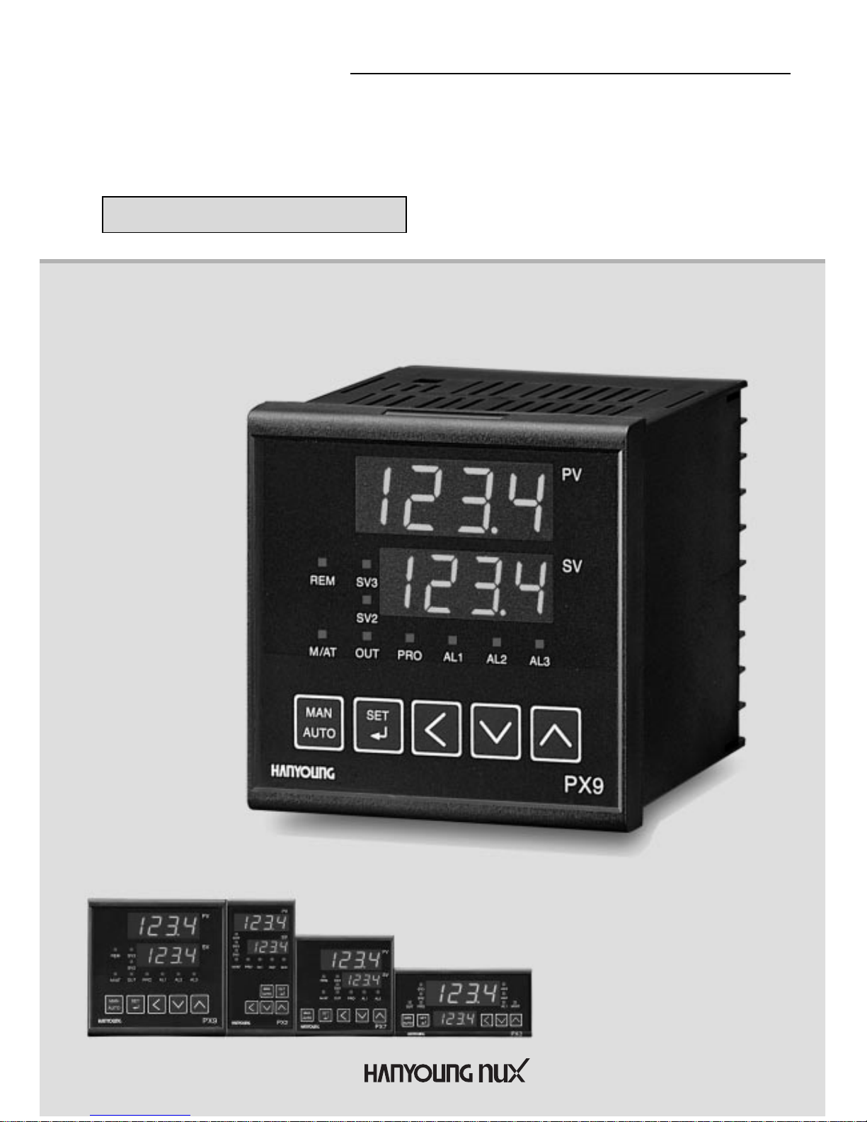
PX series
INSTRUCTION MANUAL
Thank you for the purchase of HANYOUNG product.
Please read this manual carefully.
Process Controller
هرﮐ ﮓﻧﺎﯾﻧﺎھ تﻻوﺻﺣﻣ یرﺎﺻﺣﻧا هدﻧﯾﺎﻣﻧ ناوﯾﺳ تﮐرﺷ
021-33989001
www.sivancarno.com
021-33989002

Contents
2
1. SAFETY INFORMATION
2. INSTRUCTION
3. ORDERING INFORMATION
4. SPECIFICATION
5. DIMENSIONS & PANEL CUTOUT
6. TERMINAL ARRANGEMENT
7. NAME & FUNCTION
8. TABEL OF SETTING ITEMS
9. SETTING METHOD
10. CONTROL GROUP
11. INPUT GROUP SETTING
12. INPUT SIGNAL AND
MEASUREMENT RANGE
13. OUTPUT GROUP SETTING
14. SET VALUE GROUP SETTING
15. PROGRAM GROUP SETTING
16. AUTO TUNING
17. P.I.D GROUP
18. ALARM GROUP SETTING
19. ALARM TYPE AND CODE
20. RETRANSMISSION GROUP
21. COMMUNICATION
22. HEATER BREAK ALARM GROUP
23. REMOTE INPUT GROUP
P. 3
P. 5
P. 5
P. 6
P. 10
P. 11
P. 12
P. 13
P. 15
P. 16
P. 17
P. 18
P. 19
P. 20
P. 21
P. 22
P. 23
P. 24
P. 25
P. 26
P. 26
P. 27
P. 27
هرﮐ ﮓﻧﺎﯾﻧﺎھ تﻻوﺻﺣﻣ یرﺎﺻﺣﻧا هدﻧﯾﺎﻣﻧ ناوﯾﺳ تﮐرﺷ
021-33989001
www.sivancarno.com
021-33989002

Fuzzy
Auto Tuning
Alarm Output
Retransmission Output
Multi Input Output
External Contact Input
Ramp soak function
Heating / Cooling
Zone PID
Group PID
Power supply for sensor
Output Limits
Interface (RS485 / 422)
3 Set points
Heater break alarms
(HBA1, HBA2)
IP65 Front facia
High Accuracy 0.1 class 250 ms
Features
PX Series
هرﮐ ﮓﻧﺎﯾﻧﺎھ تﻻوﺻﺣﻣ یرﺎﺻﺣﻧا هدﻧﯾﺎﻣﻧ ناوﯾﺳ تﮐرﺷ
021-33989001
www.sivancarno.com
021-33989002
Before using, please read this (SAFETY INFORMATION) and then use this controller.
It is important that the instructions in this manual are followed when using this instrument.
Please keep this manual for future reference.
Precautions are classified in WARNING and CAUTION.
WARNING
1. Caution on wiring
Use an external protection circuit if a fault in the control loop could possibly lead to a serious
problem.
This instrument do not have a switch for power and a fuse, so please set them if it is needed.
(Fuse rating 250 V, 0.5 A)
2. Power supply
Use a rated voltage to prevent damage or trouble.
To avoid electrical shock or damage, do not turn ON the power until the wiring is completed.
3. Prohibit use in gas atmosphere
Do not use it at a place exposed to combustible or explosive gas.
4. Handling of unit
To avoid malfunction, electrical shock or fire, this unit must not be disassembled or repaired.
Do not touch the terminals to avoid electrical shock or malfunction.
5. Caution on maintenance
Turn OFF the power before mounting or removing the instrument.
To ensure continuous and safe operation of the instrument, periodical maintenance is
recommended. Some parts are limited in life.
The warranty period is 1 year only if using in the correct way.
CAUTION
1. Caution on handling
Do not install the instrument under any of the following conditions.
The ambient temperature exceeds 0 ~ 50
The ambient humidity exceeds 45 ~ 85 % RH.
A place where temperature changes suddenly or icing occurs.
A place exposed to corrosive gas or combustible gas.
Vibration or shock is likely to be transmitted to the instrument.
A place exposed to water, oil, chemicals, steam, sunlight.
A place exposed to much dust, salt or iron.
A place with much inductive disturbance, static electricity, magnetism noise.
A place where heat such as radiant heat stays.
4
WARNING
CAUTION
There is a possibility of death or heavy injury when handling in wrong way.
There is a possibility of injury or physical damage when handling in wrong way.
SAFETY INFORMATION
1
هرﮐ ﮓﻧﺎﯾﻧﺎھ تﻻوﺻﺣﻣ یرﺎﺻﺣﻧا هدﻧﯾﺎﻣﻧ ناوﯾﺳ تﮐرﺷ
021-33989001
www.sivancarno.com
021-33989002
5
2. Installation
Attach the brackets (2 units) on the fixed halls and tighten with a screwdriver.
Fixing torque is about 147 N. cm (1.5 kg.cm)
(Care should be taken not to tighten forcedly)
3. Caution on terminal connections
To avoid induction noise to input wires seperate from the power and output wires.
Keep input wires away from output wires and use shielded wires to earth.
Use a compensating cable with thermocouple.
For R.T.D input use a cable which is a small lead wire resistance and without resistance
difference to 3 wires.
If the wiring has noise, use the following step: connect a surge absorber to the conductor coil
side if the conductors are connected to the load output, such as the relay contact output.
(EX. For 220 V AC ENC 471D-05A)
Use an insulating transformer with a noise filter when the power suppy has much noise.
(EX. TDK brand ZMB 22R5-11 noise filter)
Noise filter should be mounted on a panel which has been earthed and the wiring between the
noise filter output and the instrument power terminals should be shorten.
It is effective to use a twisted cable for power supply against noise.
The heater power supply and the instrument power supply should be connected using the
same power suppy when a heater break alarm.
Time for preparation of contact output is required at power ON. When the output signal is used
for an extenal interlock circuit, connect a delay relay.
4. For load circuit connection
Use an extra relay when the frequency of operation is rather high. SSR output type is
recommended.
Electromagnetic switch : Proportional cycle time is Min. 30 sec
SSR : Proportional cycle time is Min. 1 sec
Contact output life : Mechanical : 10 million times (no load)
Electrical : 100 thousand times (rated load)
SSR drive pulse voltage, 4 ~ 20 mA DC are not insulated with internal circuit.
Use non-grounded sensor to R.T.D and thermocouple.
5. For waterproof (Waterproof type)
The instrument has IP65. Use rubber packing when installing the instrument to panel.
Please attach the rubber in correct way.
6. Caution on key operation / trouble
If alarm function is not set correctly, alarm output can not be operated at a trouble point.
Be sure to check the alarm operation.
If the input cable is disconnected, the display shows “ ”.
When replacing the sensor, please turn OFF the power suppy.
7. Other
Do not use organic solvents such as alcohol, benzine when cleaning. (Use neutral detergent)
هرﮐ ﮓﻧﺎﯾﻧﺎھ تﻻوﺻﺣﻣ یرﺎﺻﺣﻧا هدﻧﯾﺎﻣﻧ ناوﯾﺳ تﮐرﺷ
021-33989001
www.sivancarno.com
021-33989002

6
This instrument has process-value (PV) and set-value (SV) each 4 digits with 7 segment FND.
This instrument is available in 2 versions: Universal Type and Heating / Cooling Type. Each has
12 Setting groups (refer pages 9 & 10)
Function and feature : Group P.I.D, Multi-input (19 types), Multi-output (Relay, SSR, Current),
Local input, Remote input, External contact input, Program Control (Ramp / Soak) with 10 steps,
Auto-tuning 2 types (standard type, low PV type), Manual output, Retransmission, Communication
(RS485 /422), Power supply for sensor, 22 types of alarm, Sampling cycle 250 ms, 0.1 % FS high
accuracy.
ORDERING INFORMATION
INSTRUCTION
2
3
PX2 -
Process Controller (48
96 mm)
Universal
Heating / Cooling
0
1
Description
Suffix code
Model
PX3 -
Process Controller (96
48 mm)
Universal
Heating / Cooling
0
1
Description
Suffix code
Model
PX9 -
Process Controller (96
96 mm)
Universal
Heating / Cooling
0
1
0
1
Description
Suffix code
Model
PX7 -
Process Controller (72
72 mm)
Universal
Heating / Cooling
0
1
0
1
2
3
Description
Suffix code
Model
هرﮐ ﮓﻧﺎﯾﻧﺎھ تﻻوﺻﺣﻣ یرﺎﺻﺣﻧا هدﻧﯾﺎﻣﻧ ناوﯾﺳ تﮐرﺷ
021-33989001
www.sivancarno.com
021-33989002
7
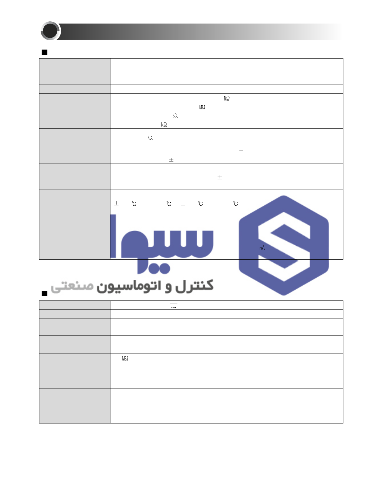
INPUT
Input
Sampling cycle time
Input resolution
Input impedance
Allowable signal source
resistance
Allowable wiring
resistance
Allowable input voltage
Noise ratio
Standard
Standard junction
temperature
compensation tolerance
Burn-out detection
Accuracy
Thermocouple, R.T.D, Direct voltage
( refer to the input signal and measurement range on page 18 )
250 mS
Below decimal point of range
Thermocouple / Voltage (mV) input : 1
or above
Voltage input ( V ) : Approx. 1
Thermocouple : 250 or below
Voltage input : 2
or below
R.T.D : 150
or below / 1 wire
Thermocouple, R.T.D, Direct voltage (mV) :
10 V
Direct voltage (V) :
20 V
NMRR :40 dB or above
CMRR :120 dB or above ( 50/60 Hz
1 %)
Thermocouple / R.T.D ( KS / IEC / DIN )
1.5 ( 15 ~ 35 ), 2.0 ( 15 ~ 50 )
OFF, Up / Down scale selectable
Thermocouple burn-out : Up / Down scale
R.T.D burn-out : Up scale
(TC / R.T.D burn-out detection current : Approx. 50
)
0.1 % of F.S
SPECIFICATION
4
100 - 240 V ~, 24 V
50/60 Hz
-10 % +10 %
Max. 6.0 W, 10 VA or below
27 V - 20 mA ( but, it is not available when using retransmission output )
20
min. (at 500 V DC)
Between primary terminal and secondary terminal
Between primary terminal and ground
Between ground and secondary terminal
2300 V AC 50/60 Hz for 1 minute
Between primary terminal and secondary terminal
Between primary terminal and ground
Between F.G and secondary terminal : 1500 V AC 50/60 Hz for 1 minute
Power supply voltage
Frequency
Voltage variation
Power consumption
Power supply for
sensor
Insulation resistance
Dielectric strength
POWER SUPPLY
هرﮐ ﮓﻧﺎﯾﻧﺎھ تﻻوﺻﺣﻣ یرﺎﺻﺣﻧا هدﻧﯾﺎﻣﻧ ناوﯾﺳ تﮐرﺷ
021-33989001
www.sivancarno.com
021-33989002
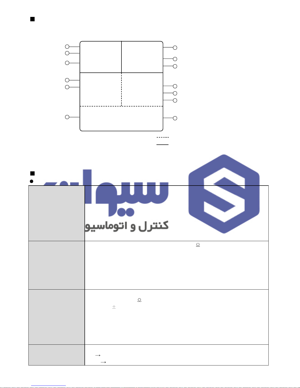
8
SELV
Danger Danger/Safety
SELV
SELV
MMI / F
Power supply
GND
Alarm1
Alarm2
Control output
Relay contact output
Control output 1 (SSR, SCR)
Control output 2 (SSR, SCR)
Contact input
Contact input
Communication channel
CT input
(retransmission)
Measuring
input
Divison of insulation
Functional insulation (basic insulation)
Functional insulation (double insulation)
OUTPUT
CONTROL OUTPUT
Relay
contact output
SSR output
Current output
Manual operation
Contact capacity : 240 V AC 3 A, 30 V DC 3 A ( Resistance load )
Contact structure : 1 c
Output action : Propotional or ON / OFF action
Proportion cycle time : 1 ~ 1000 sec.
Output limit : Higher (OH) or lower limit (OL) selectable within 0.0 ~ 100.0 %
range. It is also available in Auto tuning
ON / OFF hysteresis : 0 ~ 100 %
Time resolution : 0.1 % or 10 ms
ON voltage : 12 V DC min.(Resistance load: 600
min, 30 mA limit when short)
OFF voltage : 0.1 V DC max.
Output action : Proportional action
Proportion cycle time : 1 ~ 1000 sec.
Output limit : Higher (OH) or lower limit (OL) selectable within 0.0 ~ 100.0 %
range. It is also available in AT and MAN.
Time resolution : 0.1 % or 10ms (whichever is larger)
Output current range : 4 ~ 20 mA DC
Resistance load : 600
max.
Accuracy :
0.3 % of F. S ( 4 ~ 20 mA ) Resolution : Approx. 3000
Output ripple : 0.1 % of F. S ( p-p ) 150 Hz
Output update cycle time : 250 m sec.
Output action : P.I.D control
Output limit : Higher (OH) or lower limit (OL) selectable within -0.5 ~ 105.0 %
range. It is also available in AT and MAN.
It is changeable by A/M key, external contact and communication.
AT
MAN : TRACKING
MAN
AT : BUMPLESS CONVERSION
هرﮐ ﮓﻧﺎﯾﻧﺎھ تﻻوﺻﺣﻣ یرﺎﺻﺣﻧا هدﻧﯾﺎﻣﻧ ناوﯾﺳ تﮐرﺷ
021-33989001
www.sivancarno.com
021-33989002
9
RETRANSMISSION OUTPUT
Current output
Output current range : 4 ~ 20 mA DC, Resistance load : 600
max.
Accuracy :
0.3 % of F. S (4 ~ 20 mA), Resolution : Approx. 3000
Output ripple : 0.1 % of F. S (p-p), 150 Hz
Output update cycle time : 500 msec (When remote option)
ALARM OUTPUT ( HBA COMMON )
Alarm output
Output : Relay contact, Output contact : 3 points
Contact capacity : 240 V AC 1 A , 30 V DC 1 A (Resistance load)
Contact structure : 1 a
COMMUNICATION INTERFACE
Communication
Interface
Standard : EIA RS485
Number of devices (Max.) : 31, Address setting : 1~99 range
Communication type : 2-wire or 4-wire half-duplex
Synchronization : Asynchronous
Communication order : None
Communication distance : Max. 1200 m
Communication rate : 600, 1200, 2400, 4800, 9600
Start Bit : 1Bit, Data length : 7 or 8 Bit, Parity : None, Even, Odd
Stop Bit : 1 or 2 Bit, Protocol : PC LINK
Response time : Handling time + ( RP.T
10 ms )
HEATER BREAK ALARM
Heater break alarm
Output contact : 2 points
Current measurement range : 1 ~ 50 A AC
(Resolution 0.5 A,
5 % of F.S 1 Digit)
Alarm output : AL1, 2 output
It is available to use in ON / OFF or proportional action.
(not available in current or cooling output)
Minimum detection time : 0.2 sec, Dead Band : 0 ~ 100 %
SAFETY AND EMC STANDARDS
Safety and EMC
Standards
Safety standards: IEC1010-1-1990 and EN61010-1-1992; CSA1010 CAT
(IEC1010-1); and UL508.
EMC Standards: EN55011 Class A, Group 1, for emission (EMS); and
EN50082-2-1995 for immunity(EMI).
The indicator continuously operates within a measuring
accuracy of
20 % of the range.
EN61000-3-2, EN61000-3-3
Ambience
Installation Conditions
(for normal operation)
Ambient temperature : 0 ~ 50
Ambient humidity : 20 ~ 90 % RH (No condensation)
Installation place : Indoors, Magnetic effect : 400 AT/m max.
Vibration : 5 ~ 14 Hz, forth width 1.2 mm max.
4 ~ 150 Hz, 4.9
(0.5 G) max.
Shock : 147
(15 G), 11 msec max., Height : 2000 m max.
Installation category :
(EN61010-1), Pollution degree : (EN61010-1)
Storage temperature : -25
~ 70 , Storage humidity : 5 ~ 95 % RH
Case : Plastic
Weight : PX2 (342 g), PX3 (340 g), PX7 (344 g), PX9 (472 g)
Including brackets (Brackets 40 g)
هرﮐ ﮓﻧﺎﯾﻧﺎھ تﻻوﺻﺣﻣ یرﺎﺻﺣﻧا هدﻧﯾﺎﻣﻧ ناوﯾﺳ تﮐرﺷ
021-33989001
www.sivancarno.com
021-33989002
 Loading...