

Hanyoung HX4, HX7, HX9, HX2, HX3 Instruction Manual
-1-
MA0614E170926
※ HX9 is
chosen to explain
①
②
⑦
⑥ ⑤ ④ ③
█
External Contact Input (DI) Selection
3 predetermined set values (temperature values) could be changed with using
ON/OFF of the external 2 contact inputs
Model Code Description
HX ☐ - ☐ ☐ Multi-input and output digital temperature controller
Dimension
2 48(W) × 96(H) ㎜
PID Auto-tuning
3 96(W) × 48(H) ㎜
4 48(W) × 48(H) ㎜
7 72(W) × 72(H) ㎜
9 96(W) × 96(H) ㎜
Control output
0 Standard
1 Heating / Cooling (simultaneous control)
HX2/3/9 option
0 None
1 RS485 communication + Heater break alarm (HBA)
HX7 option
0 None
1 RS485 communication + DI 2 contacts (SV2, SV3)
2 RS485 communication + Heater break alarm (HBA)
HX4 option
0 None
1 RS485 communication + DI 1 contact (SV2)
2 RS485 communication + Heater break alarm (HBA)
1381-3, Juan-Dong, Nam-Gu Incheon, Korea,
TEL:(82-32)876-4697 FAX:(82-32)876-4696 http://www.hynux.com
HANYOUNGNUX CO.,LTD
HEAD OFFICE
Suffix code
Part name and function
Safety information
Alerts declared in the manual are classified to Danger, Warning and Caution by their criticality.
•Please install an appropriate protective circuit on the outside. Malfunction or an incorrect operation may be
a cause of leading to a serious accident.
•
Since this product does not have the power switch or a fuse, please install those separately on the outside. (Fuse rating : 250 V 0.5 A)
•To prevent damage or failure of this product, please supply the rated power voltage.
•To prevent electric shock or equipment failure, please do not turn on the power until completing wiring.
•
Since this is not explosion-proof structure, please do not use in a place where combustible or explosive gas is around.
•Never disassemble, modify or repair the product. There is a possibility of malfunction, electric shock or a risk of fire.
•Please turn off the power when mounting/dismounting of the product.This is a cause of electric shock, malfunction, or failure.
•
If the product is used with methods other than specified by the manufacturer, it may lead to injury or property damage.
•
Since there is a possibility of electric shock, please use the product as mounted on a panel while the power is being supplied.
•If it is used with systems, machines and equipment that could lead to a risk of life or property damage, please
implement safety devices and protections for both lives and the applications and plan for preventing accidents.
Warning
Do not touch or connect any undesirable conductive part to input-output terminal,
since there is a possibility of electric shock.
Danger
•The contents of the instruction manual are subjective to change without prior notice.
•Please make sure that the specification is the same as exactly you have ordered.
•Please make sure that the product is not damaged during shipping.
•
Please use this product in a place where the ambient operating temperature is 0 ~ 50 ℃ (40 ℃ max, closely installed)
and the ambient operating humidity is 35 ~ 85 % R.H (without condensation).
•Please use this product in a place where corrosive gas (such as harmful gas, ammonia, etc.)
and flammable gas do not exist.
•
Please use this product in a place where there is no direct vibration and a large physical impact to the product.
•Please use this product in a place where there is no water, oil, chemicals, steam, dust, salt, iron or
hazardous substances (Contamination class 1 or 2).
•Please do not wipe this product with organic solvents such as alcohol,
benzene or others. (Please use mild detergent instead)
•
Please avoid places where excessive amount of inductive interference and electrostatic or magnetic noise occurs.
•Please avoid places where heat accumulation occurs due to direct sunlight or radiant heat.
•Please use this product in a place where the elevation is below 2,000 m.
•
Please make sure to inspect the product if exposed to water, since there is a possibility of electric leakage or a risk of fire.
•
For thermocouple (TC) input, please use a prescribed compensation lead wire. (There will be a temperature error if a general lead is used.)
•
For resistance temperature detector (RTD) input, please use a small resistance of lead wire and the 3 lead wires should
have the same resistance. (There will be a temperature error if the 3 lead wires do not have the same resistance.)
•
Please keep the input signal wire away from the power lines and load lines to avoid the effect of inductive noise.
•The input signal wires and output signal wires should be separated from each other.
If it is not possible, please use shielded wires for the input signal wires.
•For thermocouple (TC), please use ungrounded sensors. (There is a possibility of
malfunction of the product by electric leakage, if a grounded sensor is used.)
•If there is a lot of noise from the power line, installing an insulated transformer or a noise filter
is recommended. The noise filter should be grounded on the panel and the wire between
the output of the noise filter and the power of the instrument should be as short as possible.
•It is effective against noise, if the power lines of the product are made twisted pair wiring.
•Please make sure the operation of the product before using, since the product may not
operate as it intends to if the alarm function is not properly set.
•While replacing the sensor, please turn off the power.
•In case of the high frequent operation, such as proportional operation, please use an auxiliary
relay since the life span of the output relay will be shortened if it connects to the load without
the rated margin. In this case, SSR output is recommended.
*For Electromagnetic switch : set cycle time : minimum 20 sec.
*For SSR : set cycle time : minimum 1 sec.
•Please do not connect anything to the unused terminals.
•Please connect wires properly after making sure the polarity of the terminals.
•Please use a switch or breaker (IEC60947-1 or IEC60947-3 approved)
when the product is mounted on a panel.
•Please install a switch or break near the operator to facilitate its operation.
•
If a switch or breaker is installed, please put a name plate that the power is off when the switch or breaker is activated.
•In order to use this product properly and safely, we recommend periodic maintenance.
•Some parts of this product have limited expected life span and aged deterioration.
•The warranty of this product (including accessories) is
1 year only when it is used for the purpose it was intended to under normal condition.
•When the power is being supplied there should be a preparation time for the contact output. Please
use a delay relay together when it is used as a signal on the outside of interlock circuit or others.
•When the user replaces with a spare unit due to product failure or other reason,
please check the compatibility since the operation can be varied by
the difference of setting parameters even though the model name and code are the same.
•Before using a temperature controller, there could be a temperature difference between
PV of the temperature controller and the actual temperature, so please operate the temperature
controller after correcting the temperature difference appropriately.
CAUTION
DANGER indicates an imminently hazardous situation which,
if not avoided, will result in death or serious injury.
WARNING indicates a potentially hazardous situation which,
if not avoided, could result in death or serious injury.
CAUTION indicates a potentially hazardous situation which,
if not avoided, may result in minor or moderate injury.
DANGER
WARNING
CAUTION
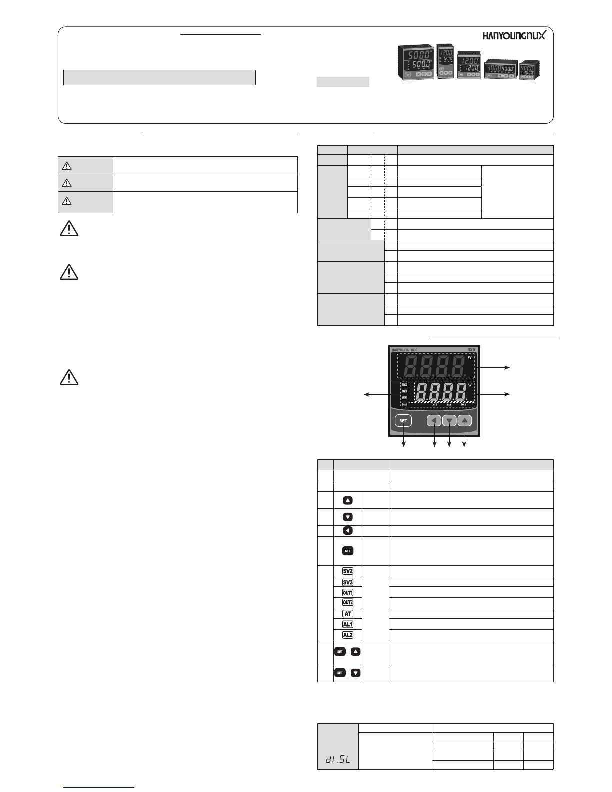
Number
Name Description
① Process value (PV) Displays the process value in the operation mode.
② Set value (SV) Displays the set value in the operation mode.
③ Up key
Increases the set value or used to move between groups and
to change an option in a parameter in setting mode.
④
Down
key
Decreases the set value or used to move between groups and
to change an option in a parameter in setting mode.
⑤ Shift key Used to move the position of the digit.
⑥ Set key
Sets (confirm) the set value, displays the output amount, or set an
option in a parameter in setting mode and moves between the
parameters in a group. By pressing for 3 seconds, it enters the
display setting mode (setting mode) or returns to the operation mode.
⑦
Operation
Indicator
Lights when SV2 is displayed.
Lights when SV3 is displayed.
OUT1 indicator.
OUT2 indicator.
Auto-tuning indicator (blink).
Alarm 1 operation indicator.
Alarm 2 operation indicator.
⑧
+
Hot
key(run/
stop)
Hot key is designated for AT or Manual MV
configuable in the group of "G.CtL"
⑨
+
Quick
menu
Sets the value: SV1, SV2, AL1, AL2
External input
contact
selection
( )
OFF (contact input is not used)
ON (contact input is used)
No display
External contact input SV2 SV3
Set value 1 display (SV1)
OFF OFF
Set value 2 display (SV2)
ON OFF
Set value 3 display (SV3)
OFF ON
Thank you for purchasing HANYOUNG product.
Please check whether the product is exactly the same as you ordered.
Before using the product, please read this instruction manual carefully.
Please keep this manual where you can view at any time.
INSTRUCTION MANUAL
HX series
Digital Temperature Controller
-2-
Input code for input type and range
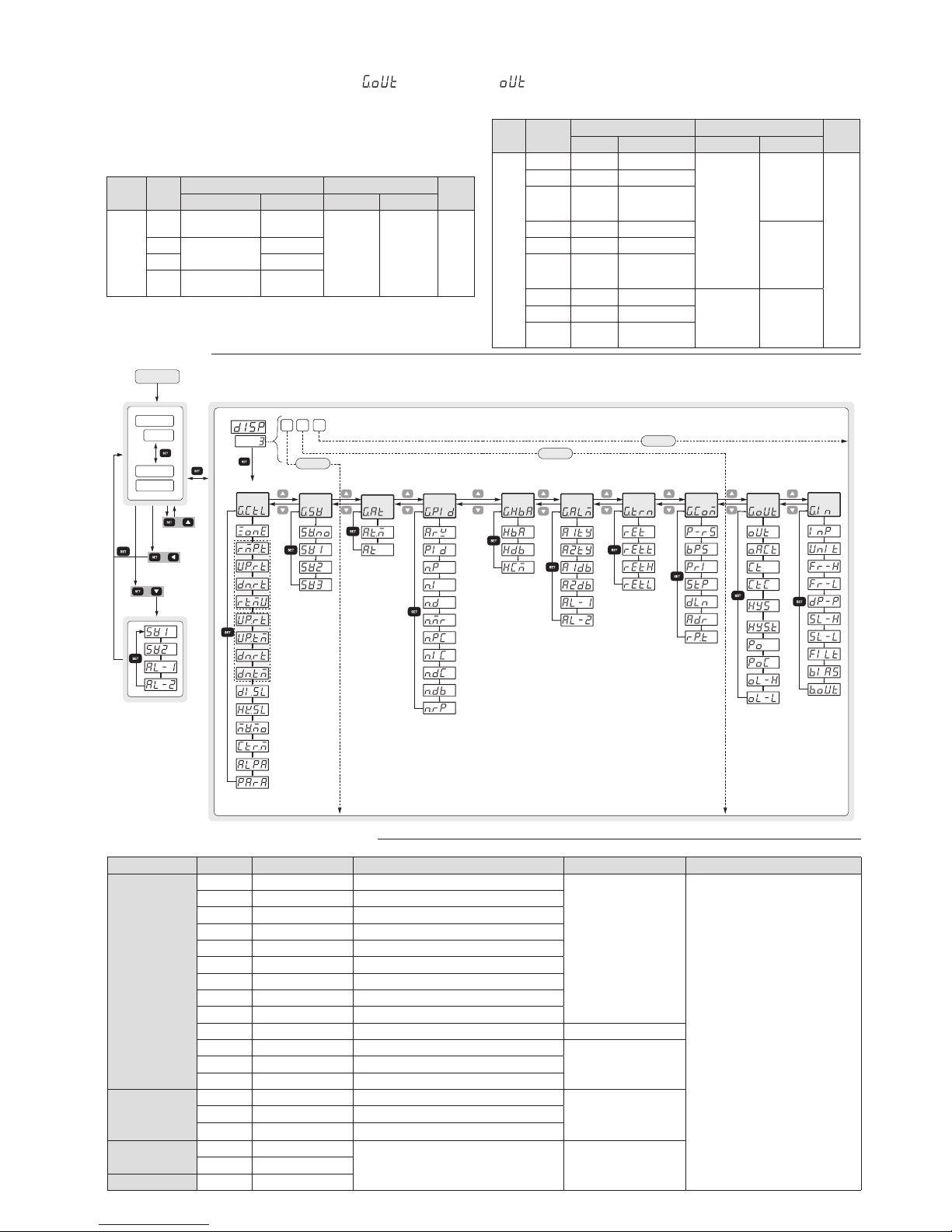
Setting Mode
56 78
9
®34
DISP 1
DISP 2
DISP 3
1 2 3
Power On
1) Operation
mode
Process value
Set value
Process value
Output amount
PV
SV
PV
SV
Control group
Auto-tuning group
Setting value group
PID group
Alarm group
RET. group
COM. group
Output group
Input group
HBA group
for 3 seconds
for 3 seconds
for 3 seconds
for 3 seconds
for
3 seconds
HOTKEY
+
Level
+
Quick menu
+
Ramp
function
type A
Ramp
function
type B
※ In the standard type, Retransmission output (RET) is only available from OUT2.
(1) Standard type
Typ e
Output
code
OUT1(Heating) OUT2
Default
Relay SSR/SCR/RET Relay
SSR/SCR/RET
Standard
Typ e
0
Control output
(ON/OFF)
AL2
(Alarm 2
output)
RET
(retransmission
output)
1
1
-
SSR
2
SCR(4 - 20 mA)
3
Control output
(PID)
-
Input signal Input signal Input type Range (℃) Accuracy Note
Thermocouple
(TC)
1 K *1 -200 ~ 1370
±0.5 % of FS ±1 Digit
•FS is the measurable range
from the maximum to the minimum
for each range.
• Digit is the minimum display value
❇1 below 0 ℃ :
±1.0 % of FS ± 1 digit
❇2 0 ~ 400℃ range :
±10 % of FS ± 1 digit
❇3 20 KPt100 Ω (C1603)
21, 22 Pt100 Ω(IEC751)
*4 In case of using Current input,
Resistor 250 Ω 0.1 % should be
installed in the input terminal.
2 K *1 -199.9 ~ 999.9
3 J *1 -100.0 ~ 999.9
4 E *1 -100.0 ~ 999.9
5 T *1 -199.9 ~ 400.0
6 R 0 ~ 1700
7 B *2 0 ~ 1800
8 S 0 ~ 1700
9 L *1 -100.0 ~ 900.0
10 N -200 ~ 1300 ±1.0 % of FS ±1 Digit
11 U *1 -199.9 ~ 400.0
±0.5 % of FS ±1 Digit12 W 0 ~ 2300
13 Platinel II 0 ~ 1390
Resistance
temperature
detector
(RTD)
20 KPt100 Ω *3 -199.9 ~ 500.0
±0.5 % of FS ±1 Digit
21 Pt100 Ω *3 -199.9 ~ 640.0
22 Pt100 Ω *3 -200 ~ 640
DC voltage
(VDC / ㎷ DC)
30 1.000 - 5.000 V DC
-1999 ~ 9999
Scaling function(SL-H/SL-L) necessary
±0.5 % of FS ±1 Digit31 0.0 - 100.0 ㎷ DC
DC current 30 4 - 20 ㎃ DC *4
█ Control Output Composition
HX series is a multi-control-output temperature controller. It can have relay ON/OFF,
SSR voltage pulse output, 4 – 20 mA current output as a control output by selecting an option in the parameter.
If the option is chosen like below in the output parameter ( ) of the output group ( ) in standard temperature controller
0 : Relay ON/OFF control is as a control output.
1 : SSR output is as a control output.
2 : 4 – 20 mA DC current output is as a control output.
3 : Relay PID control is as a control output.
(2) Heating / Cooling Type ( simultaneous control)
Typ e
Output
code
OUT1(Heating) OUT2
Default
Relay SSR/SCR/RET Relay(AL2) SSR/SCR/RET
Heating /
Cooling
type
4 - SSR
AL2
(Alarm 2
output )
SSR
4
5 - SCR(4 - 20 mA)
6
Control
output (PID)
RET
(retransmission
output)
7 - SSR
SCR
(4 - 20 mA)
8 - SCR(4 - 20 mA)
9
Control
output (PID)
RET
(retransmission
output)
10 - SSR
Control output
(PID)
RET
(
Retransmission
output
)
11 - SCR(4 - 20 mA)
12
Control
output (PID)
-
-3-
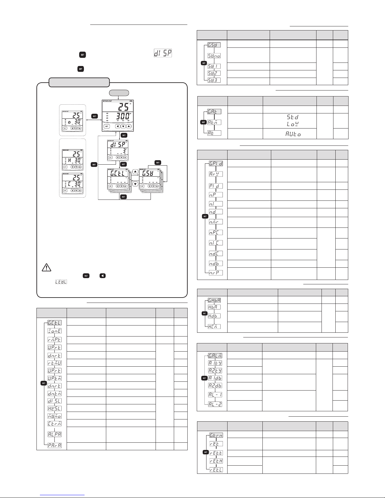
█ When turn the power ON after completing wiring
Operation Method
(1)
After the firmware version of the temperature controller appears for a short period of time, the operation
mode is running like the number ① that process value (current temperature)
and the set value are displayed.
(2) In the number ①, if button is pressed for 3 seconds, it enters
display setting mode.
It can be selected as DISP 1, DISP 2 and DISP 3 to limit displaying setting groups.
(3)
In the operation mode, if button is pressed, the output amount is displayed like the picture ⑤ - ⑥ below.
POWER ON
①
②
③
④
Output amount
display
⑤Heating Cooling type
⑥ Standard type
for 3
seconds
for 3
seconds
for 3 seconds
●
Switching between modes
How to set access levels [Level (LEVL)] and a group display [Display (dISP)]
- Setting group configuration parameters are displayed according to the group display
[Display (dISP)] setting.
- Setting group is editable depending on setting Access Level [Level (LEVL)].
Access level [Level (LEVL)]
LEVL 3 :
parameter values can be changed for all setting groups with the key of controller in front.
LEVL 2 : parameter values can not be changed for output group and input group with
the key of controller in front.
LEVL 1 :
parameter values can not be changed for Auto-tuning group(G.At), PID
group(G.PId), Alarm Group (G.ALM), retransmission group(G.trn), communication
group(G.CoM), output group(G.oUt), input group (G.In) with the key of controller in front.
Caution
In the operation mode, if and button are pressed simultaneously for 3 seconds,
it enters setting mode which prevents an operator to change parameter setting as
limiting access to the group. The default is 3rd level. The level setting mode limits the
display setting mode.
Control group
Symbol Parameter Option
Available
condition
Default
Control group Options for control mode
-
-
Zone setting OFF / ON
Control
output: PID
OFF
Ramp function type A / B
Always on
A
Ramp rising temperature
OFF/ EUS (0 ~ 100%)
Ramp
function
type A
OFF
Ramp falling temperature
OFF/ EUS (0 ~ 100%) OFF
Ramp time unit HOUR / MIN HOUR
Ramp rising temperature
OFF/ EUS (0 ~ 100%)
Ramp
function
type B
OFF
Ramp rising time 0.01 ~ 99.59(hh.mm) 0.01
Ramp falling temperature
OFF/ EUS (0 ~ 100%) OFF
Ramp falling time 0.01 ~ 99.59(hh.mm) 0.01
External contact input
OFF / ON
Always on
OFF
Hot key setting AT / A-M AT
Auto/manual setting AUTO / MAN
(1)
AUTO
Control mode
TRAD / 2DOF
TRAD
2DOF
Alpha coefficient
0 ~ 100 %
Control
mode:
2DOF
50 %
Factory reset function 0/1 [PASSWORD: 1304]
(2)
Always on 0
Set value (SV) setting group
Auto-tuning (AT) group
Symbol Parameter Option
Available
condition
Default
P.I.D group
Symbol Parameter Option
Available
condition
Default
PID group Options for PID mode - -
ANTI RESET
WIND-UP setting
Auto / 50.0 ~ 200.0 %
PID
control
100 %
PID group setting 0 / 1 ~ 3 Always on 0
n. Proportional band (P)
0.1(H/C TYPE : 0.0) ~ 999.9 %
Selecting one
of PID groups
5.0 %
n. Integral time (I)
OFF / 1 ~ 6000 s Always on 240 s
n. Derivative time (D) OFF / 1 ~ 6000 s Always on 60 s
n. Manual reset -5.0 ~ 105.0 %
Integral time:
OFF
50.0 %
n. Proportional band (PC)
for cooling
0.0(ON/OFF) / 0.1 ~ 999.9 %
heating·
cooling
5.0 %
n. Integral time (IC) for
cooling
OFF / 1 ~ 6000 s 240 s
n. Derivative time (DC) for
cooling
OFF / 1 ~ 6000 s 60 s
n. hysteresis (dead band) -100.0 ~ 50.0 % 3.0 %
n. Zone position setting
EU(0) < 1.RP < 2.RP <
EU(100 %)
PID group 1
or
PID group 2
EU
(100 %)
Heater Break Alarm (HBA) group
Alarm group
Symbol Parameter Option
Available
condition
Default
Alarm group Options for alarm mode
-
-
Alarm 1 type setting
OFF / 1 ~ 21
Refer to “Alarm type and code”
Always on
1
Alarm 2 type setting 2
Hysteresis (dead band)
of alarm 1
EUS(0 ~ 100 %)
EUS
(0.5 %)
Hysteresis (dead band)
of alarm 2
Set value of alarm 1
Absolute alarm :
EU(-100 ~ 100 %)
Deviation alarm :
EUS(-100 ~ 100 %)
EU
(100 %)
Set value of alarm 2
EU
(0 %)
Retransmission (RET) group
Symbol Parameter Option
Available
condition
초기값
RET. Group Options for RET. Group.
- -
Retransmission type
or power for sensor
Process value(PV) / set value
(SV) / output amount (MV) /
power for sensor (SPS)
RET.
option
PV
Retransmission value
4 - 20 mA / 0 – 20 mA (1) -
4-20mA
High limit of
retransmission
TC / RTD: FR-H ~ FR-L
DC voltage: SL-H ~ SL-L
( Must be RET.H > RET.L )
PV / SV
EU(100 %)
Low limit of
retransmission
EU(0 %)
(1)
If you want retransmission
0-5V
, a 250 Ω 0.1% resistor must be connected to retransmission output terminal.
If you want retransmission 0-10V, a 500 Ω 0.1% resistor must be connected to retransmission output terminal.
(1) When manual output function is selected with 'ON', 'AT indicator' lights on at the front panel.
(When auto-tuning (AT) is running, 'AT indicator' flashes at the front panel)
(2) when "1" is selected in factory reset function, PASSWORD is displayed. After input the
PASSWORD [1304], controller power turns off and on for initializing parameter values.
Auto-tuning group
Options for auto-tuning (AT) group
-
-
Auto-tuning type
setting
Standard (STD) :
Low PV (LOW) :
Control
output:
PID
STD
Auto-tuning start
setting
OFF / 1 ~ 3 / (AUTO)
OFF
Symbol Parameter Option
Available
condition
Default
Set value setting group Options for set values
-
-
Set value Number
setting
1~3 (the chosen set value is
displayed and controlled)
Always
on
1
Set value 1 (SV1) setting EU (0 ~ 100 %) EU(0 %)
Set value 2 (SV2) setting EU (0 ~ 100 %) EU(0 %)
Set value 3 (SV3) setting EU (0 ~ 100 %) EU(0 %)
Symbol Parameter Option
Available
condition
Default
Heater break alarm group
Options for HBA mode.
- -
Current setting of HBA output
OFF / 1 ~ 50 A
HBA
Option
(Refer to
“model
name and
code”
table)
OFF
Hysteresis setting of HBA
output
0 ~ 50
EUS
(0.5 %)
Current measurement value of
HBA output
Only indicates current measurement
value (0 ~ 50 A)
 Loading...