

Hanyoung BT1, BT3, BT6 Instruction Manual
SAFETY INFORMATION
Before you use, read safety precautions carefully, and use this product
properly. The precautions described in this manual contain important
contents related with safety; therefore, please follow the instructions
accordingly. The precautions are composed of DANGER, WARNING and
CAUTION.
There is a danger of occurring electric shock in the input/output terminals
so please never let your body or conductive substance is touched.
1. If there is a concern about a serious accident caused by a malfunction or abnormality of this product, please install an external protection circuit and devise a scheme for preventing an accident.
2. This product does not contain an electric switch or fuse, so the user
needs to install a separate electric switch or fuse externally. (Fuse
rating: 250V 0.5A)
3. To prevent defection or malfunction of this product, apply a proper
power voltage in accordance with the rating.
4. To prevent electric shock or malfunction of product, do not supply the
power until the wiring is completed.
5. Since this product is not designed for an explosion-protective structure, do not use it any place with flammable or explosive gas.
6. Do not decompose, modify, revise or repair this product. This may be
a cause of malfunction, electric shock or fire.
7. Reassemble this product while the power is OFF. Otherwise, it may
be a cause of malfunction or electric shock.
8. If you use the product with methods other than specified by the manufacturer, there may be bodily injuries or property damages.
9. Due to the danger of electric shock, use this product installed onto a
panel while an electric current is applied.
1. The contents of this manual may be changed without prior notification.
2. Before using the product you purchased, make sure that it is exactly
what you ordered.
3. Make sure that there is no damage or abnormality of the product during the delivery.
4. In case of the time setting is 0, please do not use since it can be a
cause of its malfunction.
5. Set the time setting while the power is OFF. Please RESET it when
changing while it is ON.
6. Do not use this product at any place with occurring corrosive (especially noxious gas or ammonia) or flammable gas.
7. Do not use this product at any place with direct vibration or impact.
8. Do not use this product at any place with liquid, oil, medical substances, dust, salt or iron contents. (Use at Pollution level 1 or 2)
9. Do not polish this product with substances such as alcohol or benzene. (Use neutral detergent.)
10. Do not use this product at any place with a large inductive difficulty or
occurring static electricity or magnetic noise.
11. Do not use this product at any place with possible thermal accumulation due to direct sunlight or heat radiation.
12. Install this product at place under 2,000m in altitude.
13. When the product gets wet, the inspection is essential because there
is a danger of electric leakage or fire.
14. If there is excessive noise from the power supply, using insulating
transformer or noise filter is recommended. The noise filter must be
attached to a panel which is already connected to a ground and the
wire between the filter output and power supply terminal must be
short as possible.
15. If twisting the power cables closely together then it is effective against
noise.
16. Do not connect anything to the unused terminals.
17. After checking the polarity of terminal, connect wires at the correct
position.
18. When this product is connected to a panel, use a circuit breaker or
switch approved with IEC947-1 or IEC947-3.
19. Install the circuit breaker or switch at near place for convenient
use.
20. Write down on a label that if the circuit breaker or switch is operating then the power will be disconnected since the circuit breaker or
switch is installed.
21. For the continuous and safe use of this product, the periodical
maintenance is recommended.
22. Some parts of this product have limited life span, and others are
changed by their usage.
23. The warranty period for this product including parts is one year if
this product is properly used.
24. When the power is on, the preparation period of contact output is
required. In case of using signals of external interlock circuit or
etc., use it with a delay relay.combining with noise, use it after
shielding it.
DANGER
WARNING
CAUTION
HEAD OFFICE
1381-3, Juan-Dong, Nam-Gu
Incheon, Korea
TEL:(82-32)876-4697
FAX:(82-32)876-4696
MAIN PRODUCTS
- DIGITAL : Temperature Controller, Counter, Timer,Speedmeter,
Tachometer, Panel Meter, Recorder
- SENSOR : Proximity Switch/Photo Electric Sensor,
Rotary Encoder, Optical Fiber Sensor,
Pressure Sensor
- ANALOG : Timer, Temperature Controller
Digital Timer
BT series
We appreciate you for purchasing HanYoung NUX Co.,Ltd
product. Before using the product you have purchased,
check to make sure that it is exactly what you ordered. Then,
please use it following the instructions below.
INSTRUCTION MANUAL
MD0301E070123
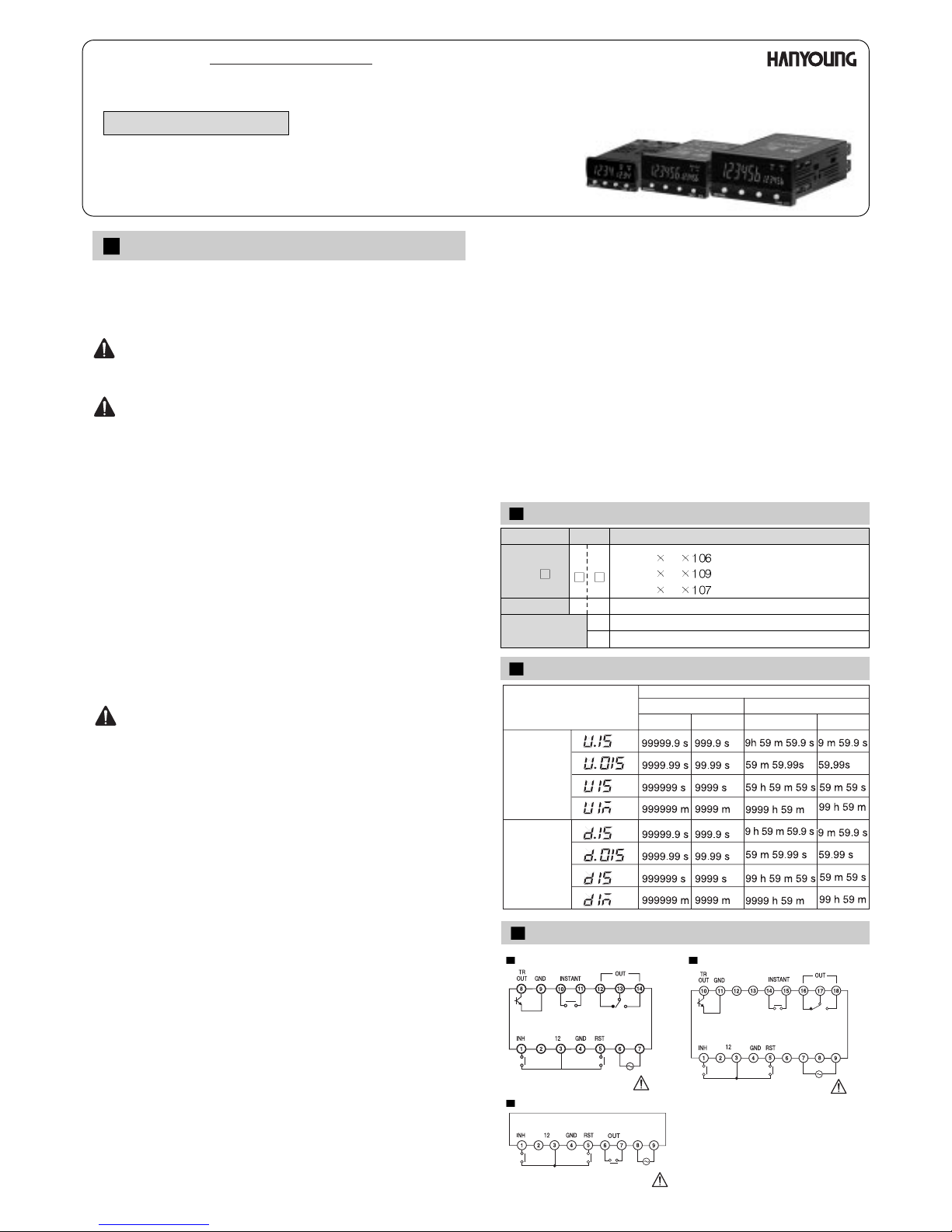
Up/Down Range Selection
Time Range
Up/Down Range
Selection
Decimal System
Sexagesimal system
Down
Up
6 Digits
4 Digits
6 Digits
4 Digits
BT
Type
Digit
1 : 48 24 mm
3 : 96 48 mm
6 : 72 36 mm
Preset
4 digits
6 digits
P
4
6
Description
Suffix code
Model
Model Name and Suffix Code
Wiring Diagram
BT6 BT3
BT1
V d.c
100 - 240 V AC
50 - 60 Hz
V d.c
100 - 240 V AC
50 - 60 Hz
100 - 240 V AC
50 - 60 Hz
Ratings
Rated Voltage
Voltage Fluctuation Rate
Power Consumption
Reset
Power for Sensor
Control Output
Operating Ambient Temperature
Operating Ambient Humidity
100 ~ 240 V AC, 50 ~ 60 Hz
10 % of Rated Voltage
About 5 VA (with 220 V AC 60 Hz)
Power Reset: Minimum Power Open Time 0.5 sec
External Reset: Minimum Input Signal
Range 0.02 sec (Common for Contact/ No Contact)
12V DC 50 mA Max.
Relay: 250 V AC 3A Resistive Load (COS
=1)
Open Collector: 30 V DC 100 mA Max.
0 ~ 55
35 ~ 85 % R.H.
Characteristics
Using Timer
Function
Insulation
Resistance
Dielectric
Strength
Impulse Voltage
Noise
Vibration
Impact
Life Span
Repeat of Operating Time
Effect of Voltage
Effect of Temperature
Above 100 (up to 500 V DC mega) Between electronic
conduction terminal and exposed non-charging metal
2000 V AC 50 ~ 60 Hz (Between electronic conduction terminal
and exposed non-charging metal)
2 KV (Between control power terminals)
Square frequency noise caused by noise simulator
2 KV (Between control power terminals)
500 V (Between input terminals)
Durability
Malfunction
Durability
Malfunction
Mechanical
Electronic
Below
0.01 % 0.05 sec (Power Start)
Below
0.005 % 0.003 sec (Reset Start)
(Rate for setting value)
10 ~ 55 Hz Double amplitude 0.75 mm
10 ~ 55 Hz Double amplitude 0.5 mm
300 m/s
2
(about 30 G)
100 m/s
2
(about 10 G)
Over 10 million times
Over 100 thousands times
(250 V AC 3 A resistive load)
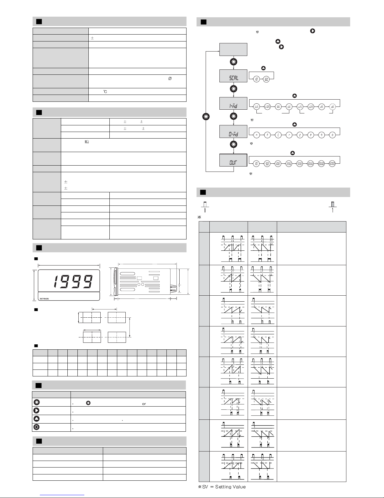
Dimension and Panel Cutout
(Unit : mm)
Dimension
Panel cutout
Model
A
48
96
72
B
24
48
36
C
100
102
100
D
24
48
36
E
5.8
7
6.5
F
100
91
89
G
11
11
H
28
16
I
13
12
J
22
44.8
30.5
K
22.5
45
31
L
45.4
92
66.5
M
45
60
60
N
65
130
100
BT1
BT3
BT6
Dimension Table
A
B
L
K
N
M
E
C
D
H
J
G
I
F
Default Specification Setting
Function
System
Time Specification
Output Mode
Output Mtheod
Mode Conditions
Sexagesimal system
Up 0.1s
N
ON DELAY
Timer Mode Selection Method
Up/Down Range
Selection
Output Mode
Selection
Decimal system/ Sexagesimal
system Selection
Up mode Down mode
Output Time
Selection
(Press key)
(Press key)
(Press key)
(Press key) Unit : ms
Power ON)
Time Setting
Mode
Press it for more than 2.5 sec
Refer to Up/Down Range Selection
Refer Output Mode
Do not select 10 ms mode in Output Time
Selection. It can be a cause of the product’s
malfunction.
For Time Setting, pressing key flashes
the digit of setting display while the power is
ON. Using key, set the setting value.
Then, press key one more time while the
last digit flashes.
Timer Output Mode
0
Reset
SV
Output
Reset
SV
Output
UP
MO
DE
DOWN Operation after Output ON
The output and display are
maintained until the reset
signal is input.
The display is continuously
processing without the setting
before reset.The output is
maintained until the reset
signal is input.
The display returns to start
status after one- short time.
The output repeatedly
operates in one-short.
The display returns to the reset
status immediately after
one-short.
The output repeatedly operates
in one-short.
The display is continuously
processing without the setting
before reset.The output
repeatedly operates in one-short.
The display is continuously
maintained during one-short
time but counting returns to the
reset start status immediately
after ON. The output repeatedly
operates in one-short.
The display is processing during
one short time but returns to the
reset start status immediately
after one-short. The output
repeatedly operates in one- short.
The display is processing until the
setting value.
The output is one-short time
ON and then one-short time OFF.
N
F
C
R
K
P
Q
A
Reset
SV
Output
0
Reset
SV
Output
0
Reset
SV
Output
0
Reset
SV
Output
0
Reset
SV
Output
0
Reset
SV
Output
0
Select one short output among 10 ~ 5000 ms
Self-maintenance Output
One-Short Output
Functions of keys
Keys
Mode
Shift Key
Incremental key
Reset Key
Functions
Press key to enter Program mode to shift to other mode
Shift to next digit
Use to increase a set value Use to select set items of each mode
Time display and initialize output
 Loading...