

Hanwha Solar HSL60P6-PC-1-xxxE, HSL72P6-PC-1-xxx, HSL72P6-PC-3-xxx, HSL60P6-PC-3-xxxE, HSL72P6-PC-3-xxxE Installation Manual
...
Sep 1, 2014
Version: HW3.819. 242SCV1 Page 1 / 11
Installation Guide
HSL60P6-PC-1-xxx(W/B)
HSL72P6-PC-1-xxx(W/B)
HSL60P6-PC-1-xxxE
HSL72P6-PC-1-xxxE
HSL60P6-PC-3-xxx(W/B)
HSL72P6-PC-3-xxx(W/B)
HSL60P6-PC-3-xxxE
HSL72P6-PC-3-xxxE
Hanwha SolarOne (Qidong) Co., Ltd.
888 Linyang Road, Qidong
Jiangsu 226200, China
www.hanwha-solarone.com
sales@hanwha-solarone.com
Note: 1. “xxx” indicates nominal power output
2. “B” denotes black diamond module
3. “W” denotes white back sheet and black frame
4. “E” denotes anti-salted property

Sep 1, 2014
Version: HW3.819. 242SCV1 Page 2 / 11
CONTENTS
1. GENERATION INFORMATION.................................................................................................... 3
1-1. Purpose Of This Guide .................................................................................................. 3
1-2. Disclaimer Of Liability................................................................................................... 3
1-3. IEC/EN61730 Information ............................................................................................ 3
1-4. UL1703 Information ..................................................................................................... 3
1-5. Safety Instruction ......................................................................................................... 4
1-6. Unpacking and storing module .................................................................................... 4
2. SYSTEM DESIGN, MOUNTING AND INSTALLATION .................................................................. 5
2-1. System Design ............................................................................................................... 5
2-2. Mechanical Mounting .................................................................................................. 5
2-3. Module Specification .................................................................................................... 6
2-4. Mounting Methods For Hanwha SolarOne Modules .................................................. 6
3. ELECTRICAL INSTALLATION-WIRING ......................................................................................... 8
3-1. Correct wiring scheme .................................................................................................. 8
3-2. Solar module plug connectors ...................................................................................... 8
3-3. Use of proper components ........................................................................................... 8
3-4. Bypass Diodes ............................................................................................................... 8
3-5. Others ........................................................................................................................... 9
4. GROUNDING: ............................................................................................................................ 9
5. LIMITED ENVIRONMENTAL CONDITIONS............................................................................... 10
5-1. Operating conditions .................................................................................................. 10
5-2. Location conditions .................................................................................................... 10
6. MAINTENANCE AND CARE ..................................................................................................... 10
Sep 1, 2014
Version: HW3.819. 242SCV1 Page 3 / 11
1. GENERATION INFORMATION
Hanwha SolarOne is a leading manufacturer of silicon ingots, wafers, PV cells and modules, delivering reliable
products at competitive pricing on a global scale. We provide world-class PV technology, efficient manufacturing,
and local customer support.
We are committed to providing technical and installation support for our customers worldwide.
This Installation Guide covers installation of the following Hanwha SolarOne modules:
IEC 1000V
HSL60P6-PC-1-xxx (W/B); HSL72P6-PC-1-xxx (W/B); HSL60P6-PC-1-xxxE; HSL72P6-PC-1-xxxE
UL 1000V
HSL60P6-PC-3-xxx (W/B); HSL72P6-PC-3-xxx (W/B); HSL60P6-PC-3-xxxE; HSL72P6-PC-3-xxxE
1-1. Purpose Of This Guide
This guide contains important information regarding the installation, safe handling and maintenance of
photovoltaic modules made by Hanwha SolarOne. The word “module” as used in this guide refers to one or more
PV modules.
All instructions should be read and understood prior to installing the modules. The installer should conform to all
the safety precautions in this guide when installing the modules. Local standards and regulations should also be
followed during installation. Before installing a photovoltaic system, the installer must be familiar with the
mechanical and electrical requirements for such a PV system. Keep this guide in a safe place for future reference.
SolarOne provides technical support worldwide. Visit www.hanwha-solarone.com for contact information.
1-2. Disclaimer Of Liability
The installation techniques, handling and use of the product are beyond company control. Therefore, Hanwha
SolarOne assumes no responsibility for loss, damage or expense resulting from improper installation, handling or
misuse.
Ensure that the module is used only in applications for which it is suitable (see “Installing Module”). All work on a
PV system (installation, setup, maintenance) must be carried out only by appropriately qualified and authorized
engineers. The appropriate DIN standards, construction rules and safety instructions must be followed during
installation.
1-3. IEC/EN61730 Information
Hanwha SolarOne module is designed to fulfill the criteria of Application Class A requirements according to
IEC/EN61730-part1.
The modules are qualified for application class A: Hazardous voltage (IEC61730: higher than 50V DC; EN61730:
higher than 120V), hazardous power applications (higher than 240W) where general contact access is anticipated
(Modules qualified for safety through EN IEC61730-1 and EN IEC61730-2 within this application class are
considered to meet the requirements for Safety Class II).
1-4. UL1703 Information
1. Rated electrical characteristics are within 10% of measured values at Standard Test Conditions of: 1000W/m2,
25°C cell temperature and solar spectral irradiance per ASTM E892 or irradiance of AM 1.5 spectrum.
2. The standoff height should be at least 4.0 in. If other mounting means are employed, this may affect the UL
Listing.
3. The modules have been evaluated for a maximum positive or negative design loading by UL1703.
4. Wiring methods should be in accordance with the NEC.
5. For installations in Canada, the installation shall also be in accordance with CSA C22.1, safety Standards for
Electrical Installations, Canadian Electrical Code, Part 1.
6. The use of the following hardware is required in order to provide a reliable grounding connection to the
module frame: a combination of the following stainless steel hardware: Serrated washer, Spring washer, flat
washer, a size M4 nut, and bolt M4x30mm -- (see illustration grounding for details).
Sep 1, 2014
Version: HW3.819. 242SCV1 Page 4 / 11
1-5. Safety Instruction
PV modules generate electricity as soon as they are exposed to sunlight. One module generates a safe, extra low
voltage level, but multiple modules connected in series (summing the voltage) or in parallel (summing the current)
represent a danger. The following points must be noted when handling the solar modules to avoid the risk of fire,
sparking and fatal electric shock.
1-6. Unpacking and storing module
Utmost attention is required when handling module. The following guidelines should be followed with caution
while unpacking, transporting and storing the modules:
Additionally, unpacking module carton box with care and follow blew instructions:
1. Cut the packaging with care avoid hurting people;
2. Carry module out of carton box with two or more people;
3. Carry modules with proper method in case of module breakage;
4. Place the module with proper support, do not place one on top of each other.
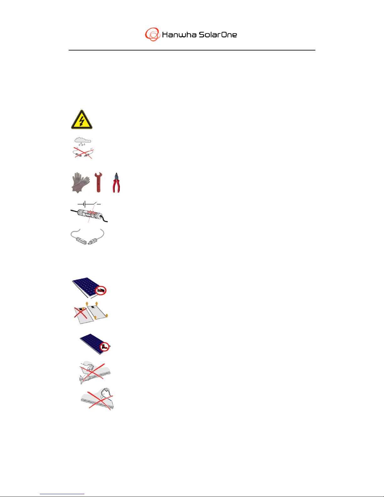
Do not insert any electrically conducting materials into the plugs or sockets.
Do not fit solar modules and wiring with wet plugs and sockets.
To avoid the generation of an electric arc, ensure the connectors are clean and have
not been contaminated, and that the electrical connection and mechanical joint are
good.
Make sure that the connection is made when the circuit is cut off. Do not disconnect
under load.
Make sure to use proper safety equipments (insulated tools, insulated gloves, etc.)
when wiring.
Do not strike or physically damage the module.
Carry modules with both hands. Do not use the connection socket as a handle;
Avoid cutting and damaging the frame during handling and installation.
Do not stand on the module.
Do not twist the module.
Do not mark on the rear of the module using sharp objects.
 Loading...