

Page 1

Device Configuration
Front View Figure
Elevation View Figure
① TFT Color LCD
Back View Figure
Quick Guide Ver2.0 Page 1
Page 2

Display the function menu and user information.
② Navigation Key ↑
Press ↑keys to select the target function in the menu.
③ Navigation Key ↓
Press ↓ keys to select the function in the menu.
④ Left Sensor
Capture the face images.
⑤ Right Sensor
Capture the face images.
⑥ LED
Located around the sensor, provide enough light for
sensor to capture the face images.
⑦ OK-Confirmation key
If there is prompt information popup or options need to be
confirmed, press OK to confirm the operation.
⑧ ESC----Return/Cancel key
Under the selection prompt or input states, press ESC to
cancel the current operation. When the system under the
sub-interface, press ESC to exit the current interface, and
return to the upper interface.
⑨ Index/ Numeric key
Index list key: Under the menu state, each number
corresponding to each option in the menu, press any
number key to select and operate the corresponding
function in the menu.
Quick Guide Ver2.0 Page 2
Page 3

Numeric key:Under the input state, the Numeric key 0~9
are used for inputting numbers or letters.
⑩ Backspace key
Under the input state, press this key to delete a number,
the cursor will go back a space.
⑪ MENU key
Press MENU key to shift to the Administrator Verifying
interface, user can operate the system as an
administrator after verified by the system.
⑫ USB port
Connect with USB flash driver, after verified by
administrator, user can import or export data by using the
USB flash driver.
⑬ Device installation Mounting plate
It is used for fixing the device on the wall.
⑭ Reset hole
The device will be restarted by pressing the key in this
hole.
⑮ Net cable port
Insert net cable in the net cable port, the device will be
connected with PC for any management operation
transmitting data.
⑯ Power adapter port
Standard power adapter port.
Quick Guide Ver2.0 Page 3
Page 4
⑰ Speaker
Broadcast system voice or information.
Installation Instruction
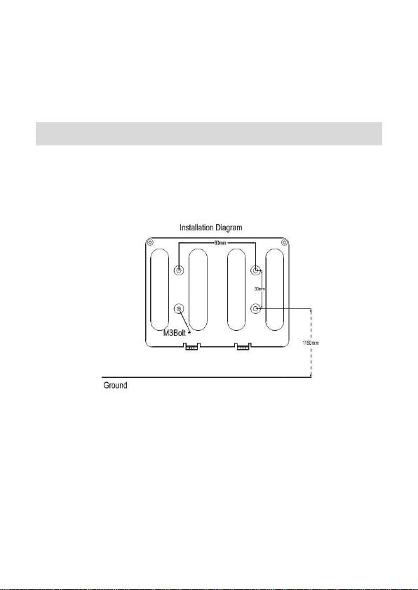
Please drill four holes on the wall according to below
diagram.
Install the Mounting plate, the vertical distance could be
1.15 meters between the two below level holes and plug
the RJ45 crystal port of net cable into the net cable port
which is located at left top side in the back of device.
Fixed the Mounting plate on the wall and please ensure
the backboard is horizontal and vertical from the ground,
and it need to be sticked with wall.
Quick Guide Ver2.0 Page 4
Page 5
Insert the fixing holes at the back of device into the
protrude pins which are placed at the Mounting plate,
then press it down softly, keep the device hanging on the
Mounting plate and stick it with the backboard, then fix
the screw at the bottom of device.
Make sure all connection finished and correct, then
power on the device.
First Entrance
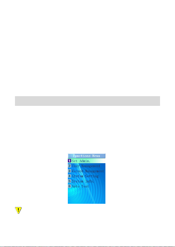
Start the system at the first time, the administrator has
not been set yet. Press MENU to enter Functions Menu
interface, following picture will be shown on the screen. Then
select “1” to enter Set Administrator operation model.
Caution:Please set one administrator at least when start to
use this device, make sure all operations are controlled by the
Quick Guide Ver2.0 Page 5
Page 6

administrator.
Set Administrator
Number of Administrators
There are five unset administrators in the system.
If an administrator is not set, the “Unset” will be displayed
at the right side.
Register Administrator
Select the number of an unset administrator to enter the
registration model.
Please follow the Enrollment Guide for face enrollment.
After face enrolled, the system will ask whether “Add as
User?”, press ESC to finish administrator setting or press
OK to enter User setting. Input the User Number, User’s
Name.
After input the user name, ”Permit Attendance” will
prompt out for settings step by step.
Hint: User can input capital/small letter and blank/dot
character synchronously when input user name. Press
“ESC” to switch model between capital and small letters.
Quick Guide Ver2.0 Page 6
Page 7

Register Finished
The register successful information will be shown on the
screen.
The system will return to “Set Administrator” interface
automatically, and the corresponding user name will be
shown at the right side.
Administrator Verification
Press MENU to enter to administrator verifying model.
After face verification successful, administrator could
enter the menu to do more settings as register user, set
system, etc.
Users will be verified during 5 seconds as a cycle for
administrator verifying. If verification failed after 3 cycles
continuously, “Recognition Failed” will be shown.
User Management
Press MENU to enter to administrator verifying model,
administrator will enter Functions Menu interface after verified
successfully, press 2 for User Management then press 1 for
register user.
Input User No.
Quick Guide Ver2.0 Page 7
Page 8
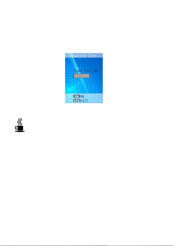
Input User Number in it as the following figure shown, the
system will inspect whether this user is existed in the
database.
Press OK to confirm, and then press ESC to quit and
return to the “Function Menu”.
Hint:Register User Parameter:
Total Capacity:500 users
User Number Range:1-99999999
User Name Length:Maximum 18 characters per person
Input Name
Input available Name in the corresponding interface. User
can input capital/small letter and blank/dot character
synchronously. Press “ESC” to switch model between capital
and small letter.
Select Authentication Method
There are two options for authentication methods, select
Quick Guide Ver2.0 Page 8
Page 9
the corresponding option for the new enrollment.
Hint:Face recognition for normal user.
Pin and Face for high security level.
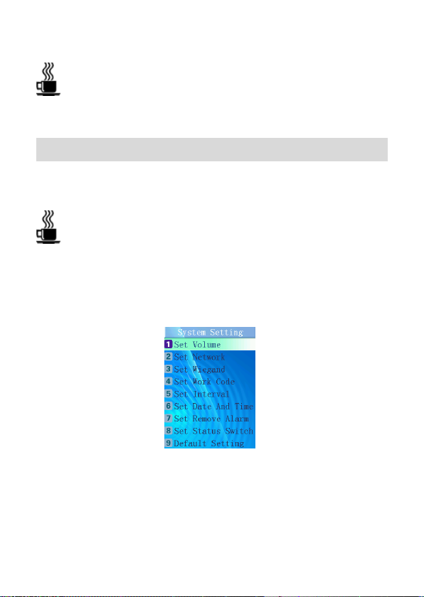
System Setting
Enter the function menu, press the corresponding number
“4” to enter System Setting.
Hint:When under system setting, press ok to confirm the
setting, then do more settings; If press ESC, the setting
will not be saved and the system will return to the “Set
System” menu.
Set Volume
Press the corresponding number to choose “High, Middle,
Low” level, or press ↑/↓ keys to shift the options, then press
Quick Guide Ver2.0 Page 9
Page 10

OK to confirm volume setting, the device will utter the correct
hint voice.
Set Network
According to the direction of networking engineer to set IP
address, mask code and gateway address.
Press OK to confirm the setting, the complete networking
information will be shown on the screen;
Set Work Code
Press the corresponding number “4” to enter Set Work
Code interface directly.
Press “Add Work Code” to set a new work code. Firstly,
input an available work code ID, press OK to confirm. Then
input name that want to be defined. Press OK to confirm the
setting and it will utter the correct hint voice.
Press “Browse Work Code” to inspect all work codes that
have been set.
Press ↑/↓ keys to choose other corresponding option
which want to be selected, and then press OK to operate this
option, or press the corresponding number key to operate the
corresponding function directly.
Related Parameter:
Work Code ID Range:1-9999
Work Code Name:Maximum 18 characters
Quick Guide Ver2.0 Page 10
Page 11

Hint:If the user have selected “Open Work Code” model,
Users will have to select corresponding work code after
verified successfully. This setting is special for time
attendance application.
Set Interval
Set time range or attendance interval. If set 2 minutes, the
first attendance log will be recorded in each 2 minutes for
every user.
Set Date and Time
Set Date and Time
Input combined numbers in y/m/d frames respectively,
cursor will jump to the next frame when finishing in the last
frame, cursor will wink in which it located, and inspect the
number’s validity automatically. When finishing, press OK to
confirm the time setting.
Set DST
Input DST Start time and End Time in m/d/h frames
respectively. Press OK to confirm the time setting.
The system time will advance an hour when it comes to
Start time and will recover when it comes to End time.
Set Remove Alarm
Select Open, the alarm will prompt automatically when
the device is removed by anyone else, select Close, the
Quick Guide Ver2.0 Page 11
Page 12

device won’t alarm when it is removed.
Set Status Switch
Press the corresponding number “8” to enter Set Status
Switch interface directly.
The System already has two Status as default setting:
1.on duty 2.off duty. Choose Add Status to add new status.
The system totally can support 8 status.
Related Parameter:
Status ID Range:3-9.
Status Name Length:Maximum 18 characters.
View all status through pressing “Browse Status”. The
system have been set “on duty” time for 9:00 and “off duty”
time for 18:00 as default. Press“ Status Switch Time” to
change corresponding status time.
Hint:Press “↓”key to select more optional status in the
recognition and Standby interface.
Default Setting
The caution information will display as the following figure
shown.
Quick Guide Ver2.0 Page 12
Page 13
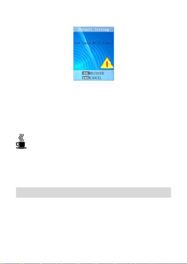
Press ESC to cancel the operation and return to the
“System Setting” menu; If press OK, the system will be
recovered to the default setting, at the same time “Clearing…,
please wait…”will be shown on the screen.
After that, “All Data Cleared!” will be shown and the
correct hint voice can be heard, the system will be restarted
automatically.
Hint: “Default Setting” means the system will clear all
users’ information. All attendance records and pictures,
all administrators and all settings will be lost and
recovered to the default setting.
Record Management
Record inquiry
Input User Number/Start time/End time to get the user’s
record.
Clear record
Quick Guide Ver2.0 Page 13
Page 14
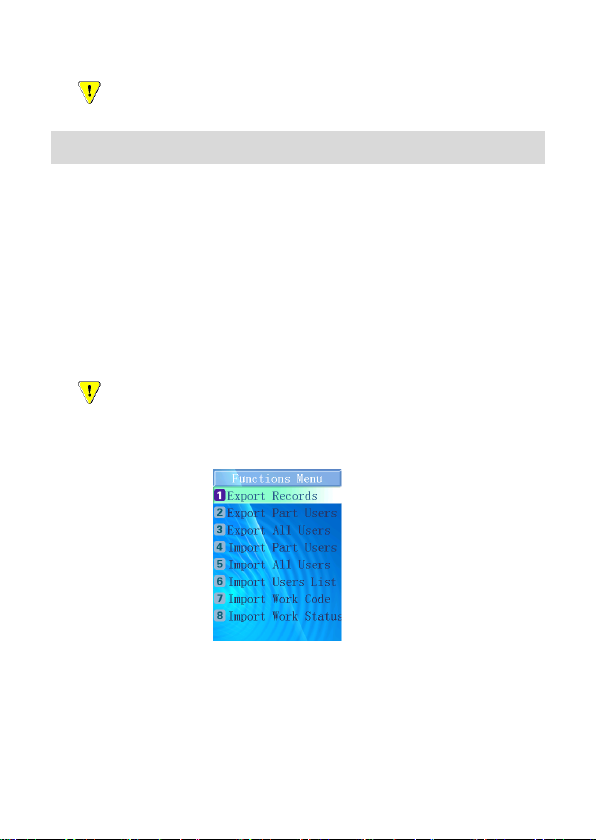
All record will lose if select Clear Record Setting.
USB Import or Export
USB Import or Export Model
Under the system standby interface, insert USB flash
driver, the system will startup administrator verifying
function automatically, after the verification, the following
figure will be shown.
Remove the USB flash driver or press ESC, the system
will return to the standby interface.
Caution:Due to the capability of chip is limited, a few
models of USB flash drive or card readers could not be
compatible with this device.
USB flash driver operation
Export records
Press number “1” to export all attendance records from
the device, the procedure percent will be shown on the screen;
Quick Guide Ver2.0 Page 14
Page 15

the data exported will form a new file named TIME.TXT in the
USB flash driver.
After that, there will be successful prompt information
display, and utter the correct hint voice. After 2 seconds, the
system will return to the “Function Menu”.
Export Part Users
Press number “2” to export the selected user’s
information, input User Number and press OK to confirm, and
then input the next one’s User No.Press ESC to finish the
selection, the system will export the information that had been
selected before.
During the exporting process, the procedure percent will
be shown on the screen. There will be successful prompt
information display when it finished, and utter the correct hint
voice. After 2 seconds, the system will return to the “Function
Menu”. The data exported will form a new file named
Quick Guide Ver2.0 Page 15
Page 16

USER.TXT in the USB flash driver.
Export All Users
Press number “3” to export all users’ information. During
the exporting process, the procedure percent will be shown on
the screen. There will be successful prompt information
display when it finished, and utter the correct hint voice. After
2 seconds, system will return to the “Function Menu”. The data
exported will form a new file named UAERALL.TXT in the
USB flash driver.
Import Part Users
Press number “4” to import the users’ information saved
in USER.TXT file from the USB flash driver to the database in
the device. During the importing process, the procedure
percent will be shown on the screen. The imported data will
add up or cover the former data according to the User Number.
There will be successful prompt information display when it
finished, and utter the correct hint voice. After 2 seconds,
system will return to the “Function Menu”.
Import All Users
Press number “5” to import the users’ information saved
in USERALL.TXT file from the USB flash driver to the
database in the device. During the importing process, the
Quick Guide Ver2.0 Page 16
Page 17
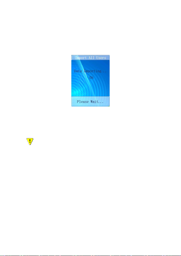
procedure percent will be shown on the screen. The imported
data will add up or cover the former data according to the User
Number.
There will be successful prompt information display when
it finished, and utter the correct hint voice. After 2 seconds,
system will return to the “Function Menu”.
Caution: When import part users or all users, the
imported file must be .TXT format which is exported from the
device, and the contents must not be modified.
Import Users List
Press number “6” to import the users’ number&name
information that saved in USERLIST.TXT file from the USB
flash driver to the database in the device. The imported data
will add up or cover the former data according to the User
Number. The device will utter the correct hint voice when
finishing import.
Quick Guide Ver2.0 Page 17
Page 18

Import Work Code
Press number “7” to import the users’ number&name
information that saved in WORKCODE.TXT file from the USB
flash driver to the database in the device. The imported data
will add into the device that will utter the correct hint voice
when finishing import.
Import Work Status
Press number “8” to import the users’ number&name
information that saved in STATUS.TXT file from the USB flash
driver to the database in the device. The imported data will
add into the device that will utter the correct hint voice when
finishing import.
Face Recognition
When a user step towards the device about 0.5 meter,
the device will apperceive and startup face recognition
function automatically, face recognition interface will be
shown on the screen, it will be the color figure, there is a
green sector brush go around deasil continuously and
the green circle line frame will direct user to aim at
sensor.
Quick Guide Ver2.0 Page 18
Page 19

When face detected successfully, the green line frame
will display on the screen, and a green stick will scan
user’s image from top to bottom for detecting user’s face.
Face recognition and user searching will be finished at
the same time.
During the detection process, the system will provide
some prompt information for user, such as: “Please Get
Closer”, “Please Get Farther” and” Adjust Your Action”.
Pin and Face Recognition
If some users cannot be detected well, press the
backspace key “ ← ” to enter the input ”User No.”
interface, input the user number first and then perform
face verification.
If the User Number input is not existed, the prompt
information will be shown and system will return to the
input “User No.” interface.
Quick Guide Ver2.0 Page 19
 Loading...