

Hantverksdesign 500, 800, 600 User Manual
USER MANUAL
For Tilt In Space
Hantverksdesign Wheelchair
Art.nr. 95 008-1
Rev. 021211
2
1
Side Contents
2. Identifying models
3. Wheelchairs parts
4. Brakes
5. Wheels, anti-tippers
6-8 Seat, back, covers, push bars
9 Arm support
10 Folding
11-13 Leg rests
14-16 Accessories
18 Maintenance
19 Technical data/measuring table
Contents
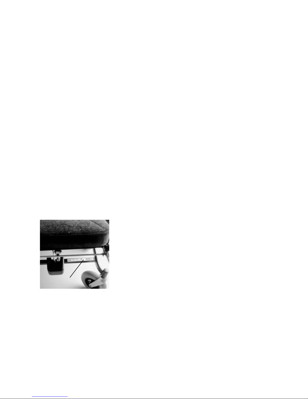
Model production number (NR)
A label with the model and the
manufacturing number of the wheelchair
is placed on the front frame of the chair
(see picture 2a)
pic 2a
This User Manual’s contents applies to the following
wheelchair models:
Model 500
Model 600
Model 800
The models with bold print are the most usual and are the ones
illustrated in this user manual.
2
12
11
13
15
14
3
1
3
5
6
4
7
8
9
10
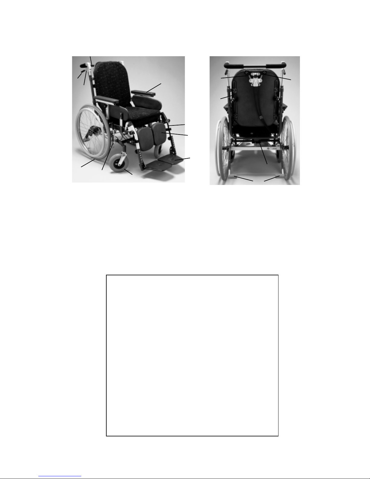
1 Leg rest
2 Foot plate
3 Ankle support
4 Driving wheel
5 Castors
6 Parking brake
7 Arm support
8 Push bar
Wheelchair parts:
pic 3a
pic 3a
9 Brake handle
10 Brake lock
11 Back adjustment lever
12 Seat adjustment lever
13 Thorasic support fastening
14 Folding pin
15 Anti tipping protection
Standard equipment:
Removable adjustable leg supports
Arm rests are adjustable height/depth
Puncture free tyres
Tipping protection
Attendant assisted disc braking
Quick release wheels
Angled seating with built in pressure relief
Angled & contoured back rest
Adjustable seat depth
Removable washable seat & back cushions
Removable other fabric covers
Height adjustable push bar
Thorasic support fastening
1
2
4
8
9
3
6
7
Adjusting the tyre brake:
- Loosen the stop screws (7)
- Push the brake to or from the
tyre.
- Screw in tight to the stop
screw.
Brakes
Combined braking
All models have standard
braking equipment. Brake used
by the carer is a braking bar
located on the back of the chair
beneath the push handle. The
brake operates the disc brakes
on each wheel. NB: some
chairs can be equipped with
separate push handles but the
braking system is the same.
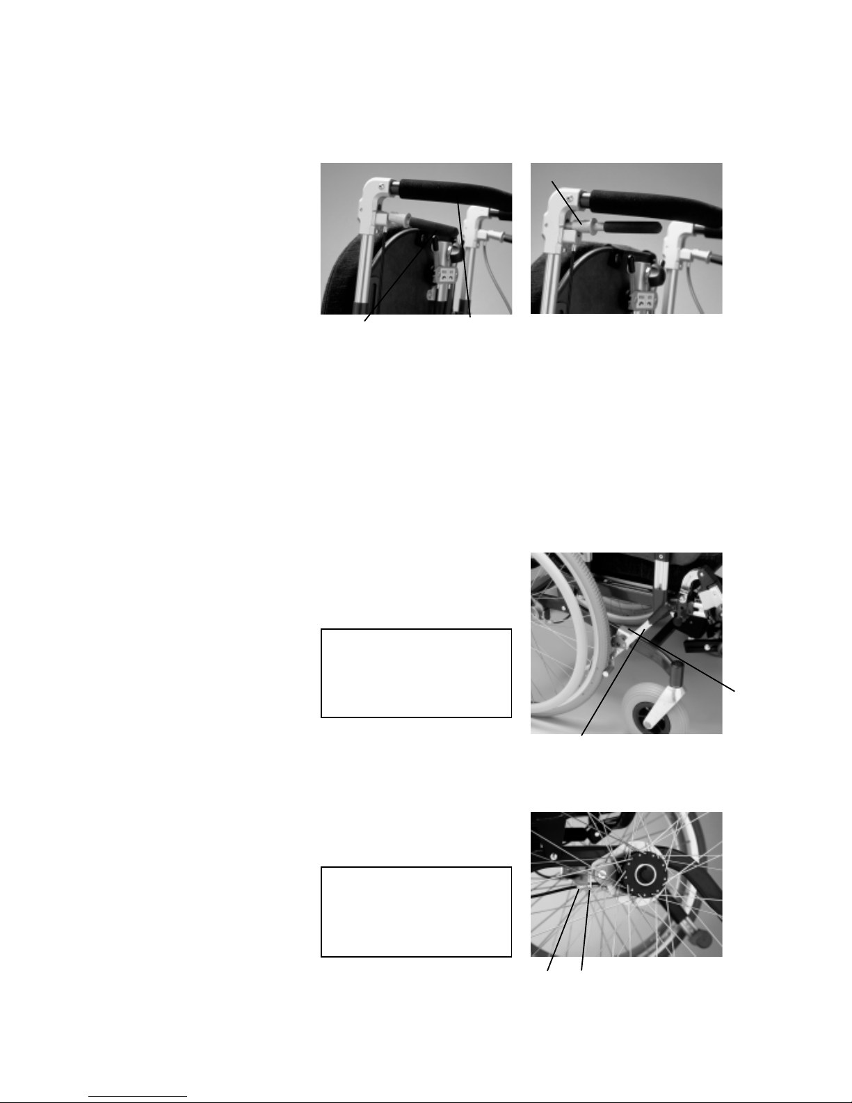
Brake bar: The brake is
manoeuvred by pulling up the
brake handle (1) against the
push bar (2) see picture 4a.
Parking brake: Pull the
braking handle (1) see
picture 4 a up towards the
push bar (2) and push the
lock sleeve forward (3) so
that the handle is locked in
the braking position, see
picture 4b
NB: One lock on each side,
make sure that the brake
sleeve is securely pushed
on so that the wheelchair is
safely braked.
pic 4a pic 4b
Parking brake on models fitted with 24” wheels:
On model 500 there is a
separate parking brake for
the user. This brake is fitted
on the wheel rim, see
picture 4c. At braking pull
the lever (6) forward from
the wheel. There is a
braking lever on each side.
Adjusting disc brakes:
The disc brakes can be
adjusted in the following
manner:
See picture 4d, loosen the
nut (8) a couple of turns. Turn
the screw (9) so that suitable
braking power is achieved.
Test the braking on the
driving handle and adjust so
that both wheels have the
same braking power and then
tighten the nut (8).
NB: To try out the braking
power the wheels must be
fitted.
IMPORTANT
adjustment of brakes should
be done by trained staff
IMPORTANT
adjustment of brakes should
be done by trained staff
pic 4c
pic 4d

1
2
3
5
1
3
4
4
All wheels are fitted with
puncture proof tyres
(pneumatic is option) . The
driving wheels are quick
release and are either 24” or
12 ½” wheels.
Releasing the wheels:
Push in the locking knob (1)
on the underside of the wheel
hub, see picture 5a. Loosen
the wheel and take off.
Mounting wheels:
Put the wheel axle into the
socket (2) on the wheel hub
see picture 5b. Push in the
lock knob (1) on the underside
of the wheel hub. Push in the
wheels so that the three metal
pegs on the wheel hub fits
into the three holes in the
braking plate. Let go of the
locking knob and check that
the wheel is on securely.
IMPORTANT
Check that the wheel
release button has locate
and that the wheel is secure.
Moving forward the driving
wheel.
This can only be done on
model 500 (not on children’s’
models)
See special documentation.
Wheels
IMPORTANT
Moving forward the driving
wheel should be done by
trained staff only.
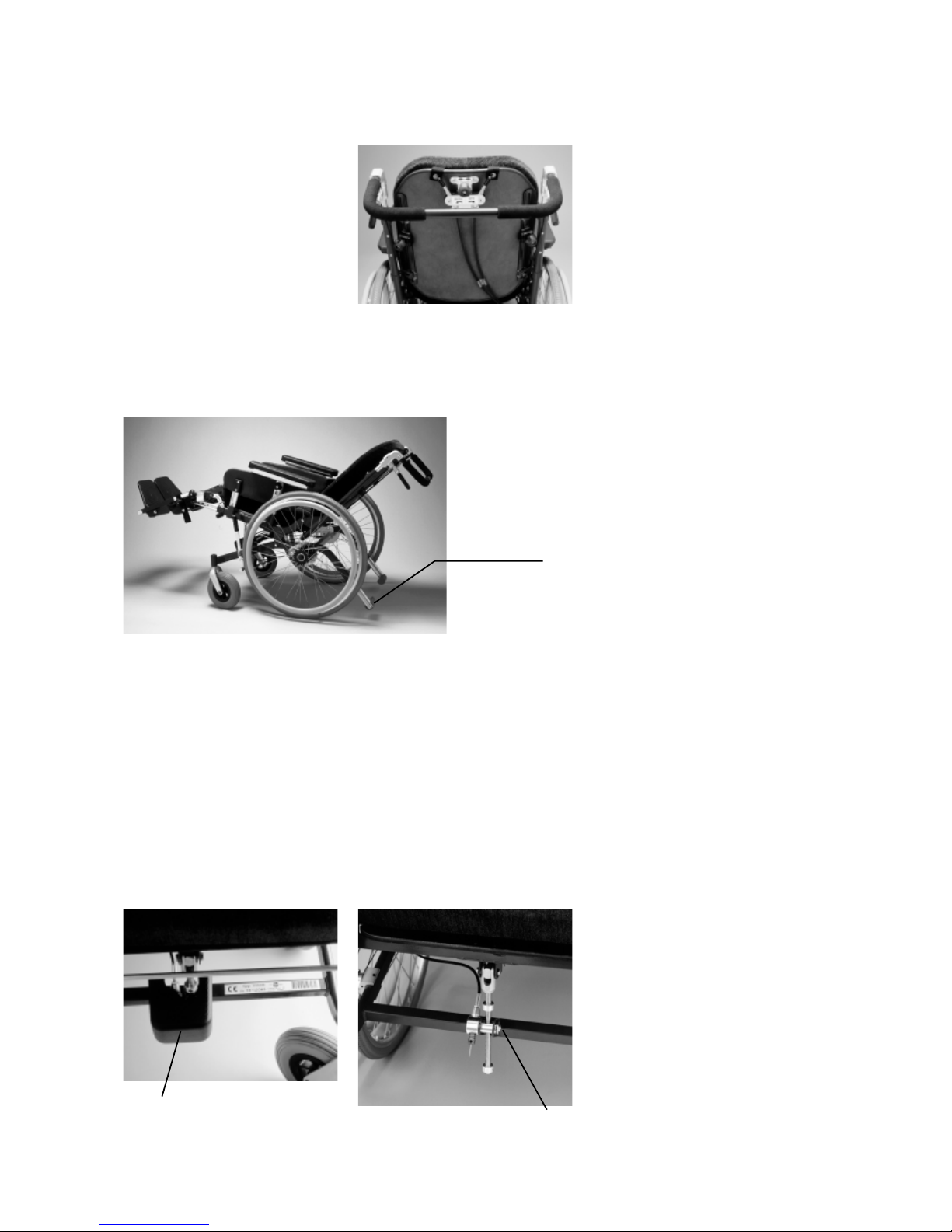
Tipping protection/bar
Tipping protection is standard
on models 500, 600 and 800.
See picture 5c and 5d. The
tipping protection can be
pulled out or pushed in (lock)
picture 5d. Please note check
the locking nut has slid out of
its hole properly.
Always have the tipping
bar extended out if there is
a risk of tipping
backwards.
picture 5a
picture 5b
picture 5c
picture 5d
1
6
2
picture 6a
The control levers for control
of the seat and back angles
are on the back of the back
support, see picture 6a. The
levers are positioned on each
side of the head rest fastening. The levers should be
handled with average force.
Picture 6b shows the chair
with the back and seat at the
maximum angle with standard
gas assisted spring mounted.
Seat and back
Tipping
protection
Back angling, left adjuster:
Control left lever.
- Grasp the driving bar with
one hand.
- Free the lever by putting
the lever to the side. Adjust
the angle by using the push
bar as a jack and let go of
the lever. Do not use the
lever as a jack. The angle
of the back is adjustable by
the gas spring with a
smooth action. As an
option there is a variant for
increasing the back angle.
The tipping risk is increased
and extended tipping
protection should be used.
See side 5.
Seat angling:
Right side: Grasp the push
bar with one hand and free
the lever by putting the
lever to the side. Adjust the
angle by using the push
bar as a jack and let go of
the lever. The angle of the
seat is adjustable into
approx 10 positions . As an
extra there is a variant for
increasing the seat angle,
with an extended tip bar.
The tipping risk should be
taken into consideration.
Please see special fitting
manual.
Seat angling mechanism.
The tipping lock is fitted with
an adjustable brake, see
picture 6d. The brake (1) is
adjusted with a Philips
screwdriver and is adjusted to
the required for resistance
and the weight of the user.
To get access to the tipping
lock the cover (2) picture 6c,
has to be removed. The cover
is fixed with spring loaded
hooks on the frame bar and
can be removed without
tooling.
picture 6d
picture 6c
picture 6b
 Loading...