

Page 1

DC Power Supply Software User Guide
● Software Installation Instructions
●
Software Use Instructions
1.1 DC Power Supply Software Installation
1.1.1 DC Power Supply Software Installation Steps:
1、Run Setup folder DPS_Setup.exe;
2、Click Next start the installation ,as show Figure 1;
Figure 1
3、Browse to choose the installation path, click Next to continue installation, as shown in
Figure 2;
1
Page 2

Figure 2
4、According to need to select the desktop shortcuts check box, click Next to continue
installation, as shown in Figure 3;
Figure 3
5、According to the need to select the shortcut icon on the desktop check box, click Next to
continue installation, as shown in Figure 4;
2
Page 3
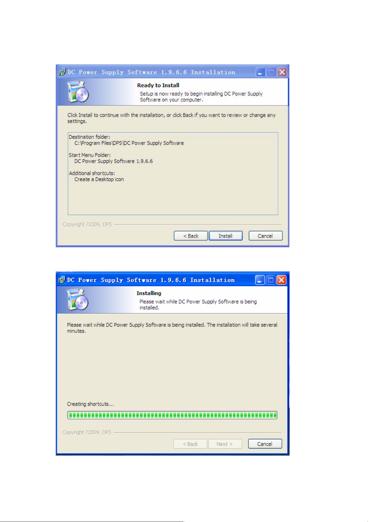
Figure 4
6、Click Install, to start the installation, as shown in Figure 5;
Figure 5
7、The installation of a buffer, as shown in Figure 6;
Figure 6
3
Page 4

8、Click Finish, end the installation,as shown in figure 7;
Figure 7
1.1.2 DC Power Supply Software after installation to generate a shortcut:
1、Generate a desktop shortcut,as shown in Figure 8;
Figure 8
2、Generated under the Start menu shortcut, as shown in Figure 9;
Figure 9
1.1.3 DC Power Supply Software Uninstall:
1、Click Uninstall, uninstall open interface, as shown in Figure 10;
4
Page 5

Figure 10
2、Uninstalling buffer, as shown in Figure 11;
Figure 11
3、Click Finish to uninstall the end, as shown in Figure 12;
Figure 12
5
Page 6
2.1 DC Power Supply SoftwareUse
1、Click Help (H) form the pull-down menu to select the software Profile;
● Black Ctrl+F5, as shown in figure 13;
Figure 13
2、Click Interface(I) the drop-down menu to select the interface
● Control Ctrl+L Interface, as shown in figure 14;
Figure 14
6
Page 7

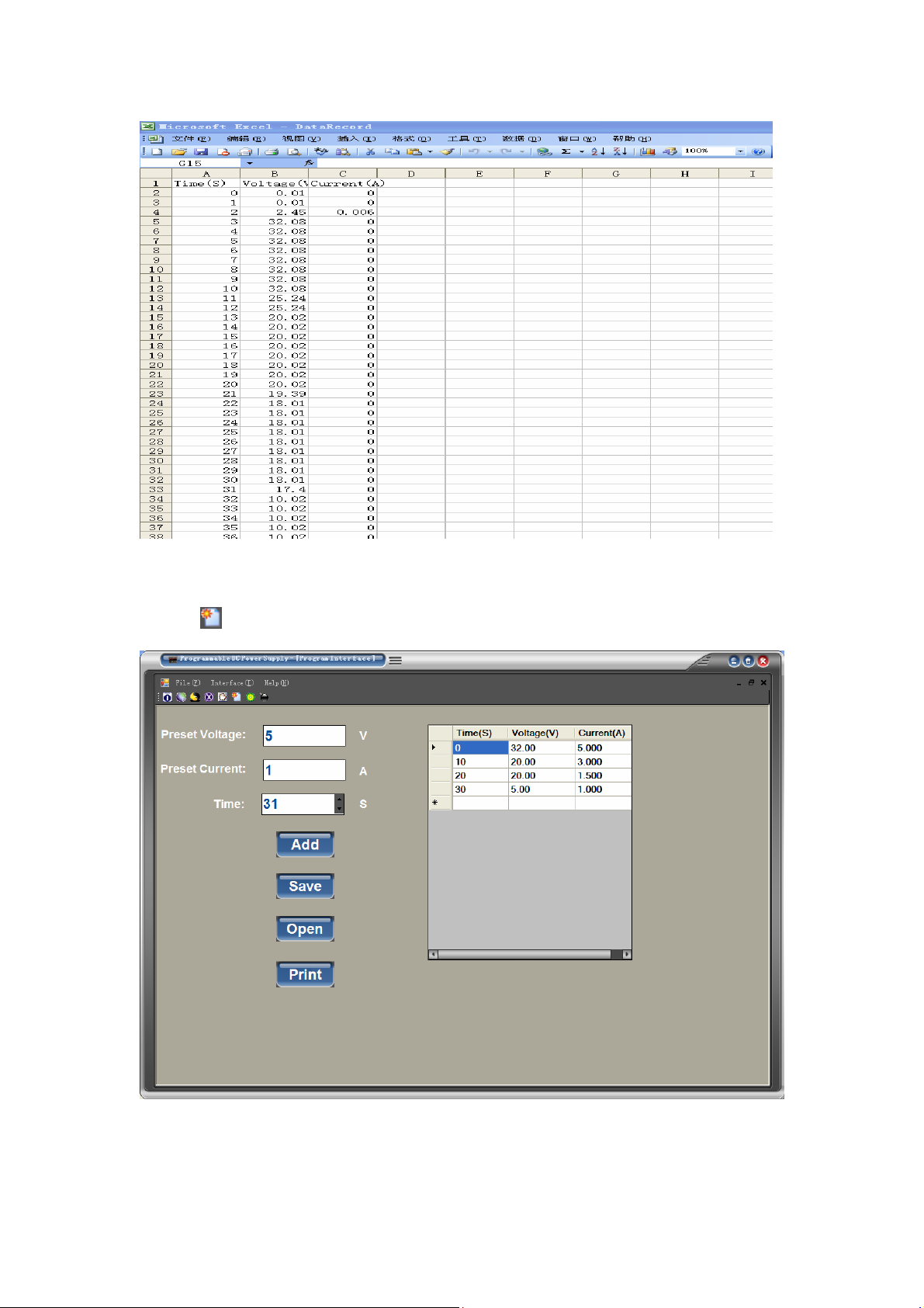
● Program Ctrl+P Interface, as shown in figure 15;
Figure 15
● Datarecord Ctrl+D Interface, as shown in figure 16;
Figure 16
2、 Click File(F), as shown in figure 17;
● Mini Ctrl+I, Minimize Form;
7
Page 8
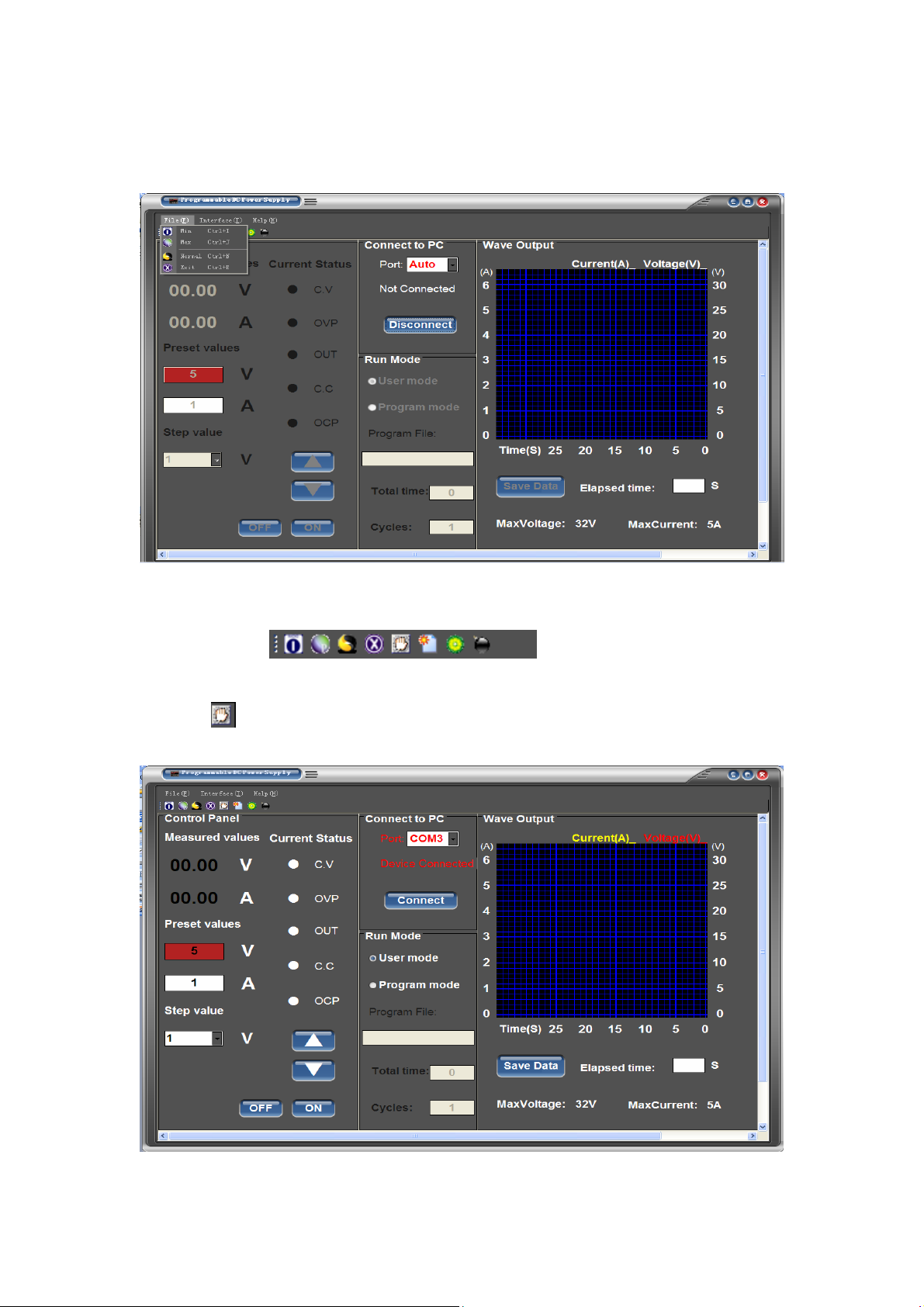
● Max Ctrl+J, Maximize Form;
● Normal Ctrl+N, Standard Form;
● Exit Ctrl+E, Exit Form;
Figure 17
3、 Click the shortcut icon, choose the realization of functions, as shown in Figure 18;
Figure 18
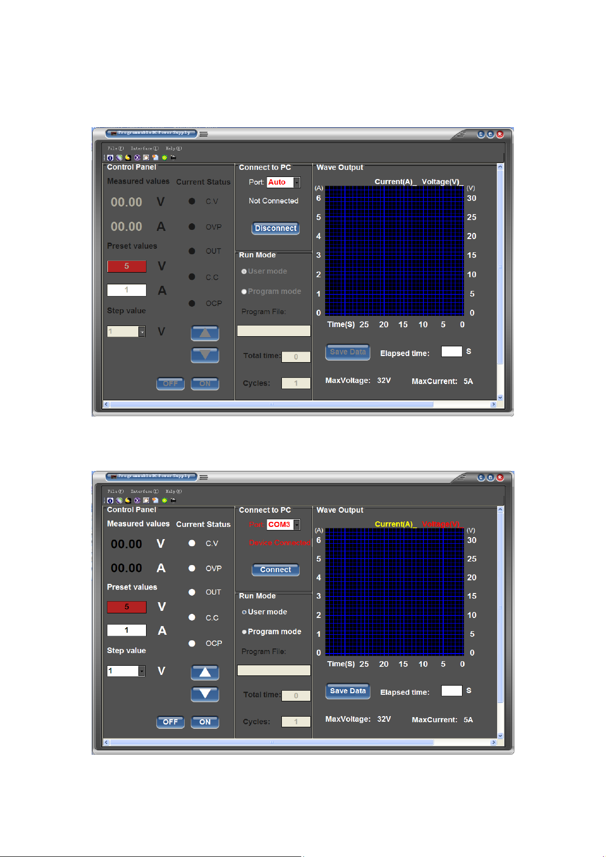
4、 Click
or Interface/Control to enter the Control Interface
● Click Disconncet to connect device, as shown in Figure 19;
Figure 19
8
Page 9

● Voltage and current output regulation
1. Click up and down keys can adjust the voltage and current,shown in Figure 21;
2. Rolling ball mouse also can regulate the output voltage and current(voltage step
value 1V Current step value 0.1A);
3. Select step value,as shown in Figure 20;
(Voltage regulator) (Current regulator)
Figure 20
4. click button regulate voltage and current values, as shown in Figure 21;
After you have already choosed the step value then you can click two button regulate
voltage and current values
Figure 21
5.Also you can modify the value of voltage,current and step values
, then click OK,as shown in Figure 22,23,24;
9
Page 10

Figure 22
Figure 23
Figure 24
If you replace or another machine ,please click Connect to disconnect from PC before pull
out USB line or close the machine
10
Page 11

● Voltage and current output, and display real-time operation waveforms, as shown in
Figure 25;
Figure 25
●Open the program file and output,as shown in Figure 26,27;
Figure 26
11
Page 12
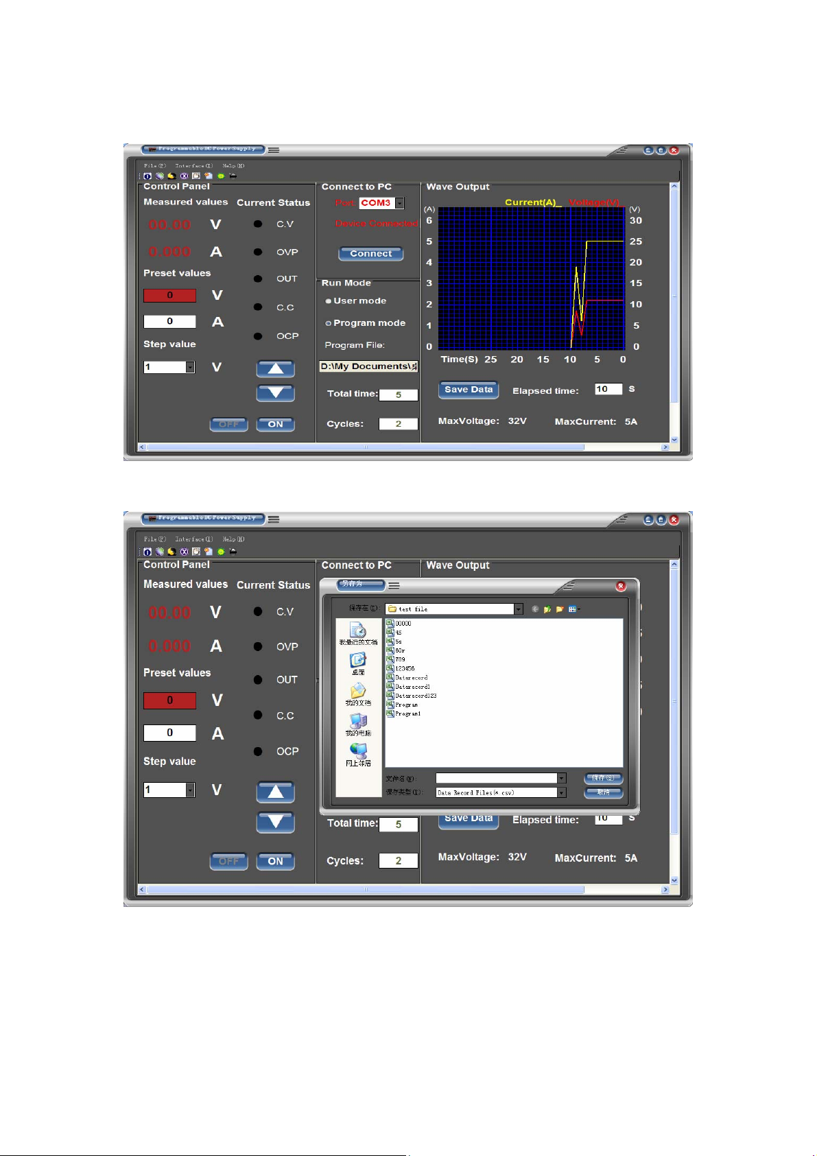
Figure 27
● Click ON and click Cycles to output the the program file data as shown in Figure 28;
Figure 28
●Save Run-off real-time data, as shown in Figure 29,,30;
Figure 29
12
Page 13
6、Click
Figure 30
or Interface/Program to enter Program interface, as shown in Figure 31;
Figure31
●Click Add to add and save programming data, as shown in Figure 32;
13
Page 14
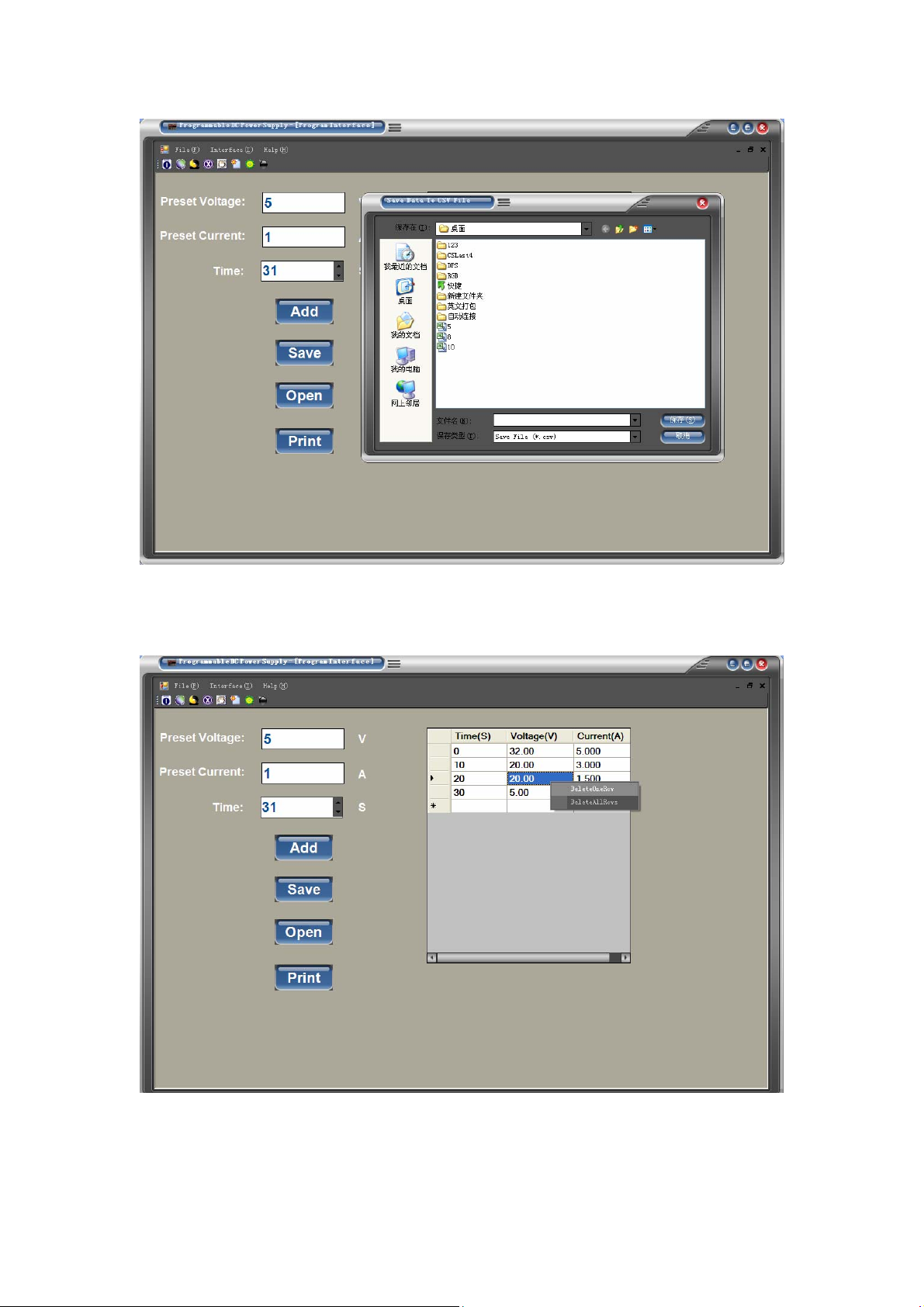
Figure32
● Right-click the mouse in the table can be deleted or all of his data, as shown in Figure
33;
Figure 33
● Click Open to open the programming of other documents, can be modified in the table,
as shown in Figure 34;
14
Page 15

Figure 34
● Click Print to print the current data in tabular form as shown in Figure 35,36;
Figure 35
15
Page 16
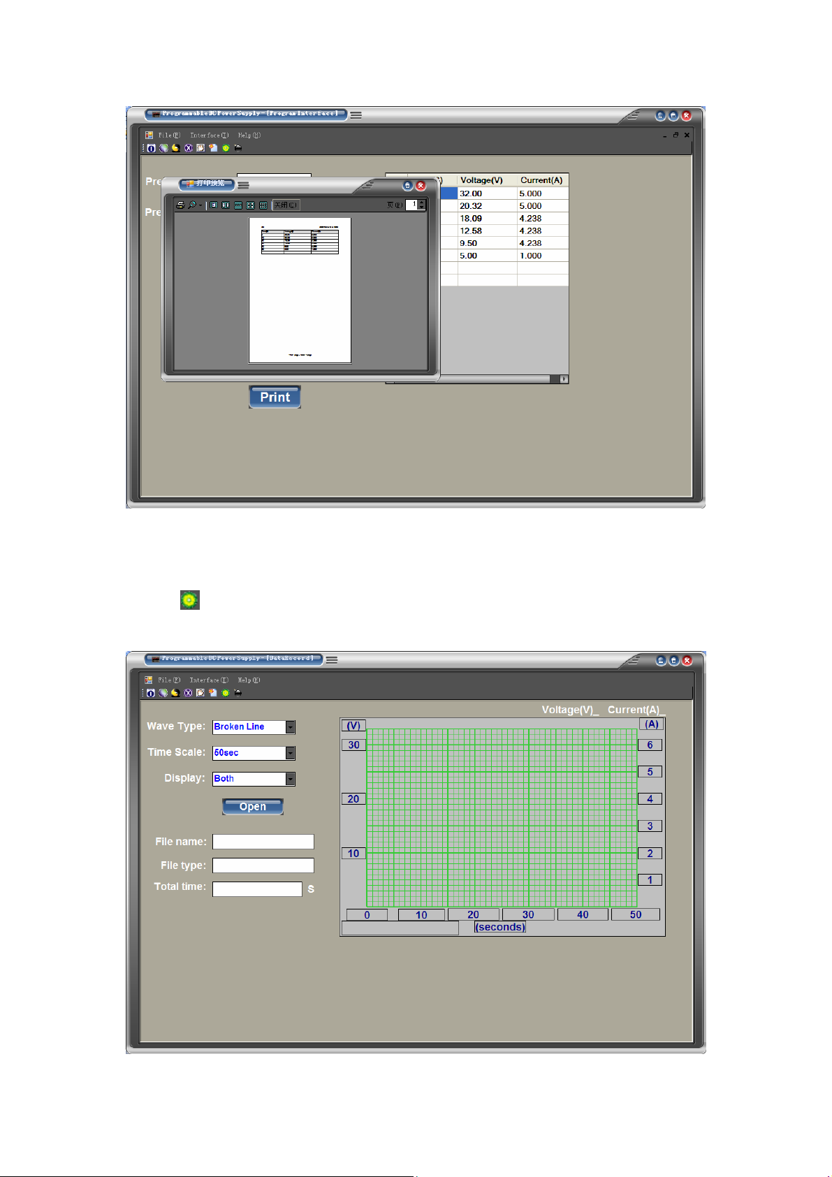
7、Click
37;
Figure 36
or Interface/Datarecord to Enter Datarecord the interface, as shown in Figure
16
Page 17
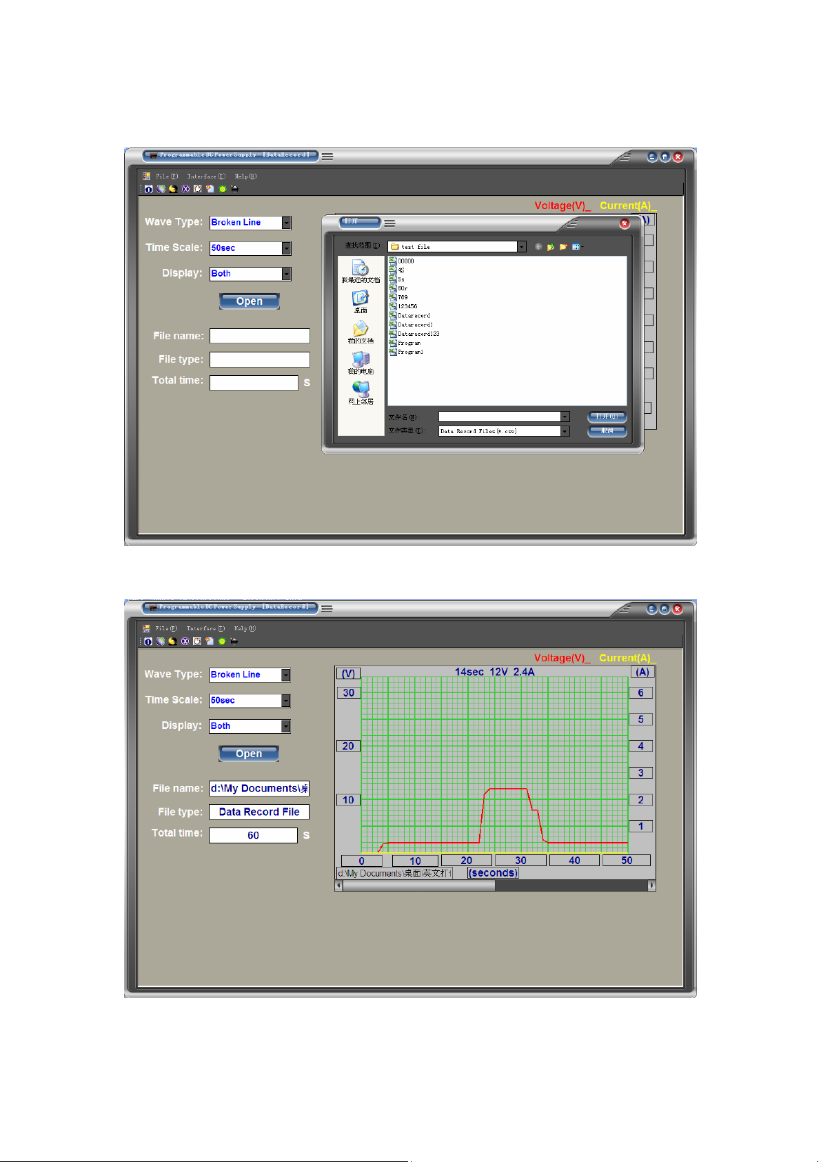
Figure 37
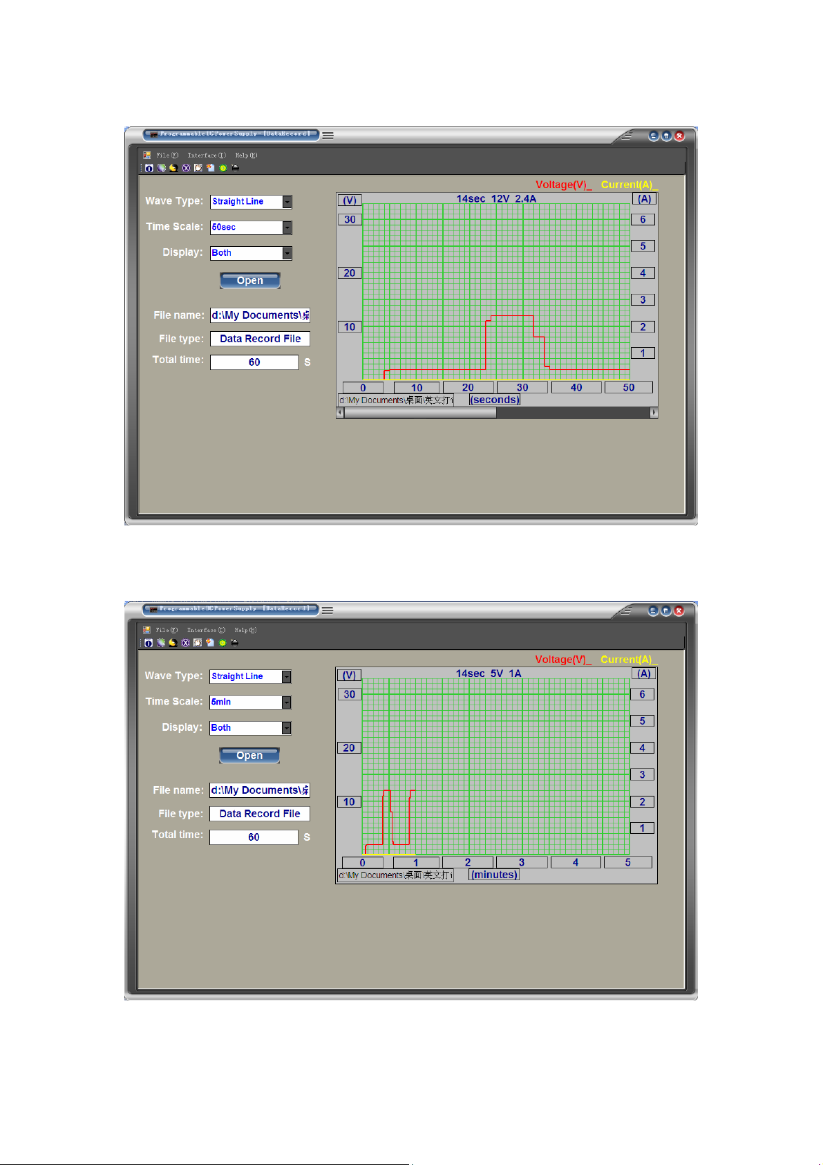
●Click Open to open to run-off data recording waveforms, as shown in Figure 38,39;
Figure 38
Figure 39
●Click the right side of the Wave Type selection box, select the waveform data record
17
Page 18
type, as shown in Figure 40;
Figure 40
●Time Scale to right click the selection box, select the length of time, as shown in Figure
41;
Figure 41
●Display the right click the selection box, choose to display the voltage or current, as
18
Page 19

shown in Figure 42,43;
Figure 42
Figure 43
19
 Loading...