

Page 1

USER’S MANUAL
Arbitrary Waveform Generator
HDG 2000 Series
V1.0.3
Page 2

Content
Copyright Declaration ....................................................................................................................... iii
General Safety Summary ................................................................................................................. iv
Chapter 1 Quick Start ....................................................................................................................... 5
1.1 Introduction to Instrument ................................................................................................... 6
1.2 Front Panel .......................................................................................................................... 7
1.3 Rear Panel ........................................................................................................................ 10
1.4 Prepare Instrument for Use ................................................................................................ 11
Chapter 2 Basic Operation ............................................................................................................. 12
2.1 Front-Panel Menu Reference ........................................................................................... 13
2.2 Utility .................................................................................................................................. 16
2.2.1 System Settings ...................................................................................................... 16
2.2.2 System Infomation .................................................................................................. 19
2.2.3 System State........................................................................................................... 19
2.2.4 Update .................................................................................................................... 19
2.2.5 Counter ................................................................................................................... 20
2.2.6 Self Test .................................................................................................................. 21
2.2.7 Calibration ............................................................................................................... 22
2.3 Save and Recall ................................................................................................................ 23
2.4 Remote Control ................................................................................................................. 24
Chapter 3 Features and Function .................................................................................................. 25
3.1 Output Configuration ......................................................................................................... 26
3.2 Pulse Waveforms .............................................................................................................. 30
3.3 Amplitude Modulation (AM) and Frequency Modulation (FM) .......................................... 32
3.4 Phase Modulation (PM) .................................................................................................... 36
3.5 Frequency-Shift Keying (FSK) Modulation ....................................................................... 38
3.6 Pulse Width Modulation (PWM) ........................................................................................ 40
3.7 Frequency Sweep ............................................................................................................. 42
3.8 Burst Mode ........................................................................................................................ 45
3.9 Trigger System .................................................................................................................. 47
Chapter4 Waveform Generation Tutorial ....................................................................................... 49
4.1 Generation of A Sine Wave Function ............................................................................... 51
4.2 Generation of A Square Wave Function ........................................................................... 52
4.3 Generation of A Ramp Wave Function ............................................................................. 52
4.4 Generation of A Pulse Wave Function.............................................................................. 53
4.5 Generation of A Noise Wave Function ............................................................................. 53
4.6 Generation of An Arb. Wave Function .............................................................................. 54
4.7 Generation of A Harmonic Wave Function ....................................................................... 54
4.8 Method of input params .................................................................................................... 55
HDG2000 Series Arbitrary Waveform Generator i
Page 3

4.9 Mode Waveform ................................................................................................................ 55
4.10 Digital Generator ............................................................................................................. 57
Chapter5 SCPI Programming Reference ....................................................................................... 61
5.1 Introduction to the SCPI Language ................................................................................... 62
5.2 Alphabetical List of SCPI Commands and Queries .......................................................... 65
5.2.1 AM Subsystem ........................................................................................................ 66
5.2.2 ASK Subsystem ...................................................................................................... 68
5.2.3 BPSK Subsystem ................................................................................................... 69
5.2.4 BURSt Subsystem .................................................................................................. 69
5.2.5 CALibration Subsystem .......................................................................................... 71
5.2.6 COUNter Subsystem .............................................................................................. 72
5.2.7 DATA Subsystem ................................................................................................... 73
5.2.8 DISPlay Subsystem ................................................................................................ 74
5.2.9 FM Subsystem ........................................................................................................ 74
5.2.10 FREQuency Subsystem ....................................................................................... 75
5.2.11 FSKey Subsystem ................................................................................................ 76
5.2.12 FUNCtion Subsystem ........................................................................................... 77
5.2.13 HARMonicSubsystem ........................................................................................... 80
5.2.14 IEEE-488 Common Commands ........................................................................... 81
5.2.15 MARKer Subsytem ............................................................................................... 82
5.2.16 MEMory Subsystem.............................................................................................. 82
5.2.17 MMEMory Subsystem .......................................................................................... 82
5.2.18 OUTPut Subsystem .............................................................................................. 84
5.2.19 PHASeSubsystem ................................................................................................ 85
5.2.20 PM Subsystem ...................................................................................................... 85
5.2.21 PSK Subsystem .................................................................................................... 86
5.2.22 PWM Subsystem .................................................................................................. 87
5.2.23 ROSCillatorSubsystem ......................................................................................... 88
5.2.24 SOURce Subsystem ............................................................................................. 89
5.2.25 SWEepSubsystem ................................................................................................ 89
5.2.26 SYSTem Subsystem............................................................................................. 90
5.2.27 VOLTage Subsystem ........................................................................................... 92
5.3 Programming Examples .................................................................................................... 93
5.3.1 Configure a Sine Wave ........................................................................................... 93
5.3.2 Configure a Square Wave ...................................................................................... 94
5.3.3 Configure a Ramp Wave ........................................................................................ 94
5.3.4 Configure a Pulse Wave ......................................................................................... 95
Appendix A ..................................................................................................................................... 96
Appendix B ................................................................................................................................... 103
HDG2000 Series Arbitrary Waveform Generator ii
Page 4

Copyright Declaration
Copyright Declaration
All rights reserved; no part of this document may be reproduced or transmitted in any form or by
any means, electronic or mechanical, without prior written permission from Hantek Technologies
Co., Ltd (hereinafter referred to as ‘Hantek’).
Hantek reserves all rights to modify this document without prior notice. Please contact Hantek for
the latest version of this document before placing an order.
Hantek has made every effort to ensure the accuracy of this document but does not guarantee the
absence of errors. Moreover, Hantek assumes no responsibility in obtaining permission and
authorization of any third party patent, copyright or product involved in relation to the use of this
document.
HDG2000 Series Arbitrary Waveform Generator iii
Page 5

General Safety Summary
General Safety Summary
Read the following safety precautions to avoid injury and prevent damage to this product or any
products connected to it. To evade potential hazards, use this product only as specified.
Only qualified personnel should perform maintenance.
Avoid fire or personal injury.
Use suitable power cord. Use only the power cord specified for this product and certified for the
country of use.
Ground the product. This product is provided with protective earth terminals. To minimize shock
hazard, the instrument must be connected to the AC power mains through a grounded power
cable, with the ground wire firmly connected to an electrical ground (safety ground) at the power
outlet. Any interruption of the protective (grounding) conductor or disconnection of the protective
earth terminal will cause a potential shock hazard that could result in personal injury.
Check all terminal ratings. To avoid fire or shock hazard, check all ratings and markings on the
product. Refer to the product manual for detailed information about ratings before making
connections to the product.
Do not operate without covers. Do not operate this product with covers or panels removed.
Avoid exposed circuitry. Do not touch exposed connections and components when power is
present.
Do not operate with suspected failures. If you suspect there is damage to this product, have it
inspected by qualified service personnel.
Assure good ventilation.
Do not operate in wet/damp environments.
Do not operate in an explosive atmosphere.
Keep product surfaces clean and dry.
HDG2000 Series Arbitrary Waveform Generator iv
Page 6

Chapter 1 Quick Start
Introduction to Instrument
Front-Panel Introduction
Rear-Panel Introduction
Prepare Instrument for Use
Basic Operation
HDG2000 Series Arbitrary Waveform Generator 5
Page 7

Basic Operation
Model
Description
HDG2002B
5MHz 16bits resolution
Arbitrary waveforms
64M Memory Depth
HDG2012B
10MHz 16 bits resolution
Arbitrary waveforms
64M Memory Depth
HDG2022B
20MHz 16 bits resolution
Arbitrary waveforms
64M Memory Depth
HDG2032B
30MHz 16 bits resolution
Arbitrary waveforms
64M Memory Depth
HDG2062B
60MHz 16 bits resolution
Arbitrary waveforms
1.1 Introduction to Instrument
The Hantek HDG2000 Series is a series of synthesized waveform generators with built-in arbitrary
waveform and pulse capabilities.
Features:
16 bits resolution, 250MSa/s Sample rate
64 Mpts Max. arbitrary waveform Memory Depth
2 Channels output
100 MHz, 80 MHz, 70 MHz, 60 MHz, 50MHz, 30 MHz, 20MHz, 10MHz or 5MHz maximum sine
output frequency
7 inch, 16K true color TFT display, WVGA(800X480)
16 channels digital output, together with the analog channel can rebuild the more mixed signals
in daily practice
TCXO timebase standard, OCXO optional for ultra-high stability
Plenty of interfaces: USB Host, USB Device. LAN optional
Support AM, FM, PM, ASK, FSK, PSK, BPSK and PWM modulations
LXI Class C Compliant
SCPI (Standard Commands for Programmable Instruments) compatibility
Online Help
SD card
Models
This section describes the models about the HDG2000 Series of instruments.
Instrument Models
HDG2000 Series Arbitrary Waveform Generator 6
Page 8

Basic Operation
64M Memory Depth
HDG2082B
80MHz 16 bits resolution
Arbitrary waveforms
64M Memory Depth
HDG2102B
100MHz 16 bits resolution
Arbitrary waveforms
64M Memory Depth
HDG2032C
30MHz 16 bits resolution
Arbitrary waveforms
64M Memory Depth
2GB SD card
HDG2052C
50MHz 16 bits resolution
Arbitrary waveforms
64M Memory Depth
2GB SD card
HDG2072C
70MHz 16 bits resolution
Arbitrary waveforms
64M Memory Depth
2GB SD card
HDG2102C
100MHz 16 bits resolution
Arbitrary waveforms
64M Memory Depth
2GB SD card
1.2 Front Panel
Front Panel can be divided into "F0 to F6 softkeys menu area", "digital keypad area", "Function
keypad area", "Hot keypad area", "Mode keypad area", "Trigger keypad area", "Waveform Output
area", "knob and cursor arrows keypad area", and “interface of the signal and peripheral devices
area”. You can press keys and buttons on the front panel to input or output signals.
HDG2000 Series Arbitrary Waveform Generator 7
Page 9

Basic Operation
1 2 4
5
6
7
12
14
15
16
17
8
1. Menu softkeys F0-F6
2. Function waveform button
3. Channel 1 and Channel 2 Switch Button
4. Function menu
5. Knob and cursor arrows
6. Numeric Keypad
7. Channel 1 and Channel 2 output buttons
8. Trigger button
9. Channel 1 and Channel 2 output Connector
10. Sync Connector
11. Modulation signal Input Connector (for all kinds of External Modulation Signal Source)
12. High frequency Connector(24MHz to 2.7GHz) HDG2000C
13. Low frequency (24MHz or lower)/External trigger Connector
14. Digital channel
15. USB port
16. SD card port
17. On/Off Switch
Note: Press and hold any front-panel key or softkey to get context-sensitive help.
Front-Panel Number Entry
You can enter numbers from the front panel in two ways:
Use the knob and cursor keys to modify the number. Rotate the knob to change a digit (clockwise
increases). The arrows below the knob move the cursor.
HDG2000 Series Arbitrary Waveform Generator 8
Page 10

Basic Operation
Use the keypad to enter numbers and the softkeys to select units. The +/- key changes the
number's sign.
CE: Delete Key
BASP: Backspace, backspace and remove the last digit
ENT: Enter Key
Warning: For protection from electrical shock, the power cord ground must not be defeated. If
only a two-contact electrical outlet is available, connect the instrument’s chassis ground screw to a
good earth ground.
Online Help
Signal generator online help provides two kinds of view. One is content view and the other is index
view.
1. The index view is the subject of the online help content according to the ascending order of the
view. Choose index by knob, enter to go into the subject.
2. Content view shows a view of specific topic content.go into the content linked by the "link
words".
3. Press ‘Exit’ menu softkey to exit.
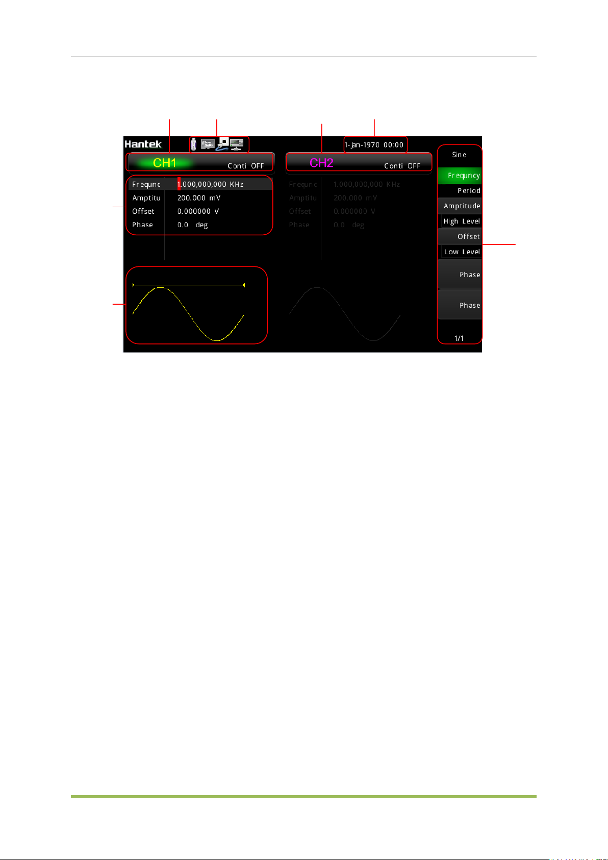
Screen Area
The signal generator can be divided into three regions: the status panel at the top of the screen,
the menu panel at the right of the screen, the window area at the left corner of the screen.
HDG2000 Series Arbitrary Waveform Generator 9
Page 11
Basic Operation
Waveform
parameters
Softkey
labels
CH1
Information
States Panel
CH2
Information
System Time
Waveform
display
Status panel indicates whether external usb device is connected with this device, whether usb
device in the rear panel is connected with PC, whether the Internet is connected and the current
time.
The menu panel and window area are corresponding. The content of the window area can be
modified by controlling the menu panel. There are three main ways of style menu panel item.
One way is operation directly. As is shown, press it, then the operation will be modified, or enter
submenu to select, or page to next page to select.
One way is for choosing. It provides a topic and some params. Topic is showed at the top of the
menu item and params showed below. Press the Softkeys F0~F6 corresponded to the item to
choose different params.
The other way is altering. It appears like choosing. But it don’t have topic item, current params is
showed on the front of the menu item and the optional item is at below.
Use F6 button to page down or page up. Press F0 to return the parent menu.
1.3 Rear Panel
1. External 10 MHz Reference Input
2. Internal 10 MHz Reference Output
3. USB Interface Connector, communication to PC software
4. LAN Interface Connector, communication to PC software (optional)
HDG2000 Series Arbitrary Waveform Generator 10
Page 12
Basic Operation
1.4 Prepare Instrument for Use
This section describes basic procedures to help you get started quickly with the instrument.
Prepare Instrument for Use
Connect the power cord as desired. Turn the instrument on by pressing the power switch in the
lower left corner of front panel.
The instrument's default function is a 1 kHz, 200 mVpp sine wave. At power-on, the channel
output connectors are disabled. To enable output on a channel connector, press the key above the
channel connector and then press the Output button.
If the instrument does not turn on, verify that the power cord is firmly connected (power-line
voltage is automatically sensed at power-on). Also make sure that the instrument is connected to
an energized power source.
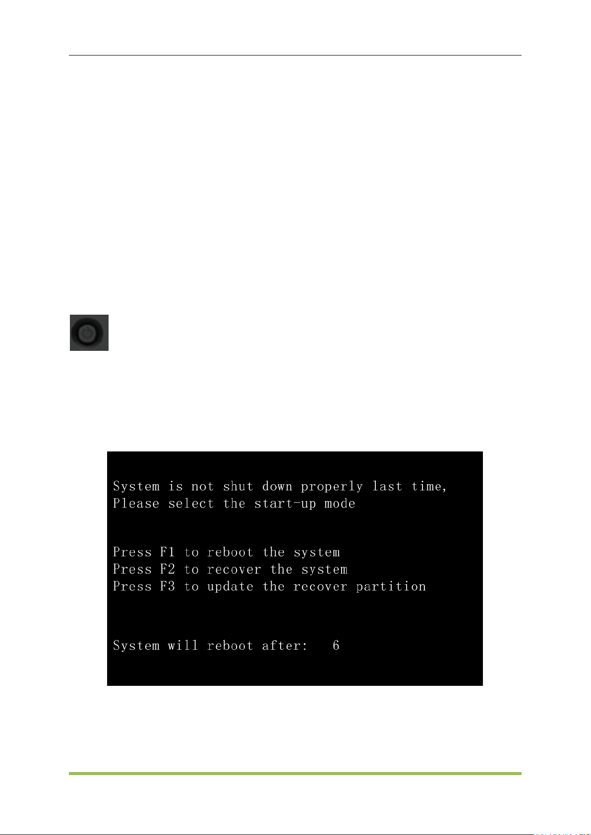
Power Switch:
To turn off the instrument, please press power switch.
Attention: After turning on, the process of system initialization will take 1~2 minutes; if you turn it
off before the initialization is done, the next time you turn it on, it will prompt that the system is not
properly shut-down. This is necessary to have the system restorable when it collapses, like the
"safe mode" of Windows.
First, press F1, the device will be restart.
If not, press F2 to recover the system, the system will be recovered to the factory default setting.
If not, contact the customer service to get new recover partition program, and press F3 to update
the recover partition.
HDG2000 Series Arbitrary Waveform Generator 11
Page 13

Chapter 2 Basic Operation
Front-Panel Menu Reference
Utility Function
Save and Recall
Remote Control
Basic Operation
HDG2000 Series Arbitrary Waveform Generator 12
Page 14
Basic Operation
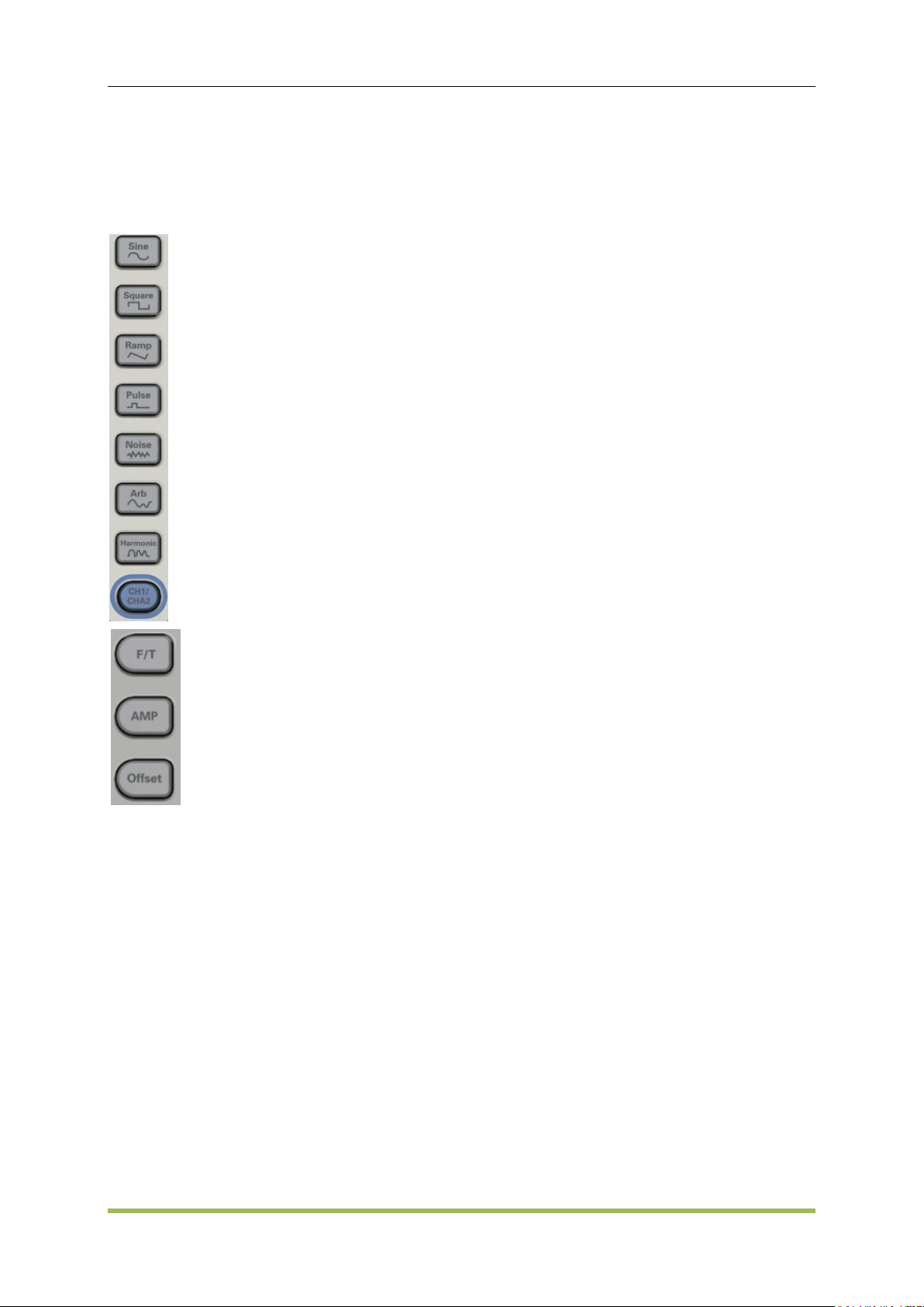
Sine
Square
Ramp
Pulse
Noise
Arb
Harmonic
CH1and CH2 switch button
Frequency/Time hot key
Amplitude hot key
Offset hot key
2.1 Front-Panel Menu Reference
Overview of the front-panel menus. The remainder of this chapter contains examples of using the
front-panel menus.
Configures waveform-specific parameters
Period/Frequency
Amplitude or High and Low Voltage
Offset
Phase
Duty Cycle
Symmetry
Pulse Width
Edge Time
Arbitrary Waveform
Bandwidth
HDG2000 Series Arbitrary Waveform Generator 13
Page 15

Specifies unit and parameter preferences
Frequency or Period
Voltage as Amplitude/Offset or High/Low
Voltage units
Pulse Width or Duty Cycle
Frequency sweep as Center/Span or Start/Stop
Mode:
Configures modulation parameters
Modulation on or off
Modulation type: AM, FM, PM, 2ASK, 2FSK, 2PSK, BPSK and PWM
Modulation source
Modulation parameters
Basic Operation
Sweep:
Configures frequency sweep parameters
Sweep on or off
Linear
Sweep time
Start/stop frequencies or center/span frequencies
Hold and return times
Burst:
Configures burst parameters
Burst on or off
Burst mode: triggered or externally-gated
Cycles per burst
Burst period
Save/Recall:
Stores and recalls instrument states
Help:
HDG2000 Series Arbitrary Waveform Generator 14
Page 16

Shows list of Help topics
Display help topic list
Display help index list
Get help on any key
Utility:
1. System setting
Basic Operation
Configures system-related parameters
Language setting: Select local language for front-panel messages and help text
Display setting: Enable or disable screen saver; Adjust display brightness
Sound setting: Enable or disable beeper
Network setting: Set network
Time and Date setting: Set date and time
Clock source setting: Select clock source internal or external.
2. System Information
Device Information
Hardware information
Software information
Law information
3. SysStatus
Check system status
Save and recall system status
4. Update
Update firmware
5. Counter
Turn on/off counter or frequency meter
HDG2000 Series Arbitrary Waveform Generator 15
Page 17

6. Self Test
Perform self test
7. Calibration
Perform calibration
8. Digital Generator
Digital Generator
Trigger:
Configures trigger settings
Perform a manual trigger, when illuminated.
Specify the trigger source for sweep, burst or arbitrary waveform advance.
Specify the trigger count and delay.
Basic Operation
Specify the slope (rising or falling edge) for an external trigger source.
Specify the slope (rising or falling edge) of the trigger output signal.
Enable / disable the signal output from the "Sync" connector.
Default setting:
Default Settings
Press the Default button in the front panel, and the factory status will be recalled.
2.2 Utility
There are some features to be selected in Utility menu, such as: <System Settings>, <System
Information>, <System State >, <Counter>, <Self Test>, <Calibration>.
To choose these features, use the knob and left/right direct button, then push ENT button to
confirm.Also you can push F1 and F2 button to choose function, then press ENT button or F4
button to confirm. Press F5 button to exit.
2.2.1 System Settings
The followings are settings:
Language Settings
Display Settings
HDG2000 Series Arbitrary Waveform Generator 16
Page 18

Basic Operation
Sound Settings
Network Settings
Time Settings
Reference Source Settings
Please follow the steps below to enter each setting:
1. Press <Utility> button, select “System Setting”, then press ENT button to do System Settings;
2. In the main menu of System Settings, push F1 to F5 button to go into desired settings
3. Also, user can choose these settings by the konb key.
Language Settings
English and Chinese Language are supported; Please follow the steps below to change current
language:
1. Press<Utility> button, select “System Setting”, then press ENT button to go into System
Settings;
2. Choose “Language Settings”, press ENT button to open Language Settings interface;
3. Push F1 button to choose different language;
4. Push F2 button to exit.
Display Settings
Adjust display brightness.
1. Press<Utility> button, and press ENT button to go into System Settings, then choose <Display>;
2. To adjust brightness, please press F1 button, then the menu is highlighted, then rotate the knob
on front panel to adjust the parameter values.
Disable or enable saver:
1. Press<Utility> button, and press ENT button to go into System Settings, then choose <Display>;
3. Push F2 button to enable or disable the saver;
4. When the saver is enable, push F3 button to determine after what time, the saver will be started;
5. Push F4 button to exit;
Screenshot function:
1. Press<Utility>button, and press ENT button to go into System Settings, then choose <Display>;
2. Press F4 button to set <Default> key to <Print>.
3. Then press <Default> to save the screenshot to external USB device.
Sound Settings
If turn on keypad tone, we can hear sound when press a button.
HDG2000 Series Arbitrary Waveform Generator 17
Page 19

Basic Operation
Please follow the steps below to enable or disable sound:
1. Press<Utility> button, and press ENT button to go into System Settings, then choose “Sound
Settings”;
2. Push F1 to enable or disable beep.
3. Press F2 to exit.
Network Settings
The system can communicate with PC by Ethernet interface.
1. Press<Utility> button, and press ENT button to go into System Settings, then choose “Network
Settings”, press ENT button to open “Network Settings” interface;
2. Press F1 to change IP address, input right format IP values by using digital keypad in the front
panel.
4. Press F2 to change subnet mask, input right format subnet mask values by using digital keypad
in the front panel.
5. Press F3 to change gateway, enter right format gateway values by using digital keypad in the
front panel.
6. Press F4 to change MAC, enter right format MAC values using digital keypad in the front panel.
7. Press F5 to exit.
Note: Not all mode of the machine has Ethernet interface.
Time Date Setting
Please follow the steps to change time and date:
1. Press<Utility> button, and press ENT button to go into System Settings, then choose “Time and
date Settings”, press ENT button to open “Time and date Settings” interface;
3. Press F1 to change year.
4. Press F2 to change month.
5. Press F3 to change day.
6. Press F4 to change hour.
7. Press F5 to change minute.
8. Press F6 to enter page 2 of main menu, and press F1 to change second value.
9. Press F6 to enter page 2 of main menu, and press F2 to exit.
Reference Source Settings
The default is 10MHz internal source. For the synchronization among different devices, please
choose external 10MHz crystals as clock source.
Please follow the steps to change reference clock source:
1. Press<Utility> button, and press ENT button to go into System Settings, then choose “Clock
HDG2000 Series Arbitrary Waveform Generator 18
Page 20

Basic Operation
Source”, press ENT button to open “Clock Source” interface.
2. Press F1 to select internal source.
3. Press F1 twice to select external source.
4. Press F2 to exit.
2.2.2 System Infomation
It contains information about the device, hardware, software and law information.
2.2.3 System State
Please follow the steps to view the system's main state:
1. Press<Utility> button, and press F2-> F2->ENT button to go into Systatus interface.
2. Press F5 to exit.
Please follow the steps bellow to save the system state file:
1. Press<Utility> button, and press F2-> F2->ENT button to go into Systatus interface.
2. Press F1 to go into <File Brower>, then select dir (File Win or Disk Win) of the file to be saved.
3. Press F3 in the <File Brower>main menu, and then name the file.
4. Press F3 again to actually save the file.
5. Then it returns to the system state window.
6. Press F5 to exit.
Please follow the steps bellow to recall the system state file:
1. Press<Utility> button, and press F2-> F2->ENT button to go into Systatus interface.
2. Press F1 to go into <File Brower>, then select dir of the saved file.
3. Press F4 to recall the file selected to recall the state.
4. Then it returns to the system state window.
5. Press F5 to exit.
Please press <Utility> button, select <SysStatus>, and press F3 to select <last> to save last time
setting. When start up next time, the system is set by last time setting.
2.2.4 Update
Please follow the steps to update the system:
1. Copy .upk file to U disk. And insert U disk into device’s USB port.
2. Press “Save/Recall” button, then press F1 to switch to “Disk Win” window, rotate the knob to
“USB” and press “Enter” button to confirm.
HDG2000 Series Arbitrary Waveform Generator 19
Page 21
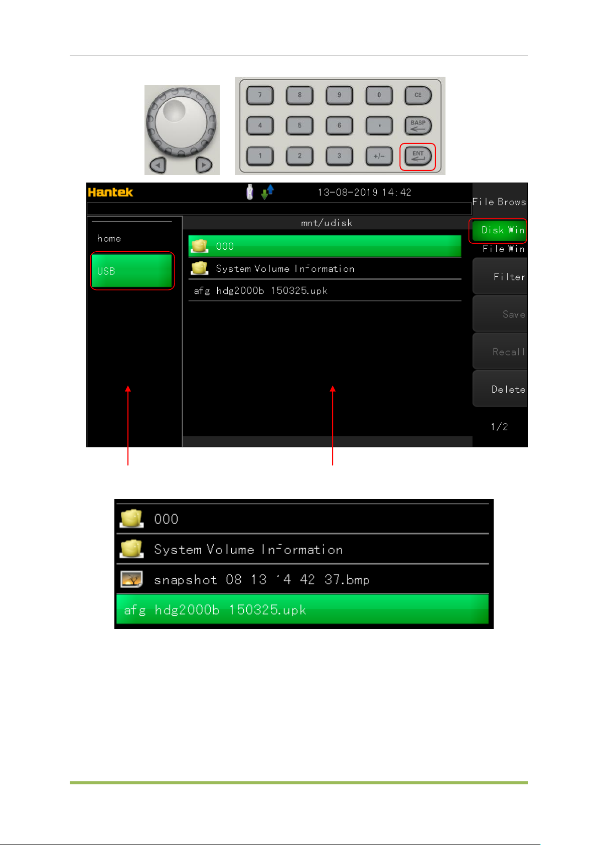
File Window
Disk Window
Basic Operation
3. Select “Recall->Update” softkey to update latest firmware.
4. Finally, please restart the device.
2.2.5 Counter
Counter function and frequency meter are also built-in the series waveform generator, including
low frequency counter, high frequency counter, low frequency meter, high frequency meter.
HDG2000 Series Arbitrary Waveform Generator 20
Page 22

Basic Operation
To measure the frequency low than 100KHz, please select low freq counter and low freq meter.
To measure frequency higher than 10MHz, please select high freq counter and high freq meter.
Please follow these steps to count low frequency signal:
1. Connect the signal to the COUNT connector in the front panel.
2. Press<Utility> button, and press F2-> F2-> F2-> F2->ENT button to go into count interface.
3. Choose low freq counter type.
4. Press F3 to start counter
5. Press F3 again to stop counter
Please follow these steps to measure the frequency of low frequency signal:
1. Connect the signal to the COUNT connector in the front panel.
2. Press<Utility> button, and press F2-> F2-> F2-> F2->ENT button to go into count interface.
3. Choose low freq meter type.
4. Press F3 to start
5. Press F3 again to stop
6. The default gate time is 1s. Please press F4 button and use knob button and digital keypad to
modify the value.
Please follow these steps to count high frequency signal:
1. Connect the signal to the COUNT connector in the front panel.
2. Press<Utility> button, and press F2-> F2-> F2-> F2->ENT button to go into count interface.
3. Choose high freq conter type.
4. Press F3 to start counter.
5. Press F3 again to stop counter.
Please follow these steps to measure the frequency of high freqency:
1. Connect the signal to the COUNT connector in the front panel.
2. Press<Utility> button, and press F2-> F2-> F2-> F2->ENT button to go into count interface.
3. Choose high freq meter type.
4. Press F3 to start
5. Press F3 again to stop
6. The default gate time is 1s. Please press F4 button and use knob button and digital keypad to
modify the value.
2.2.6 Self Test
To make sure the device can be used normally, please do self test procedure.
During the operation, real-time clock, ADC model, FPGA and the front analog circuit will be tested.
HDG2000 Series Arbitrary Waveform Generator 21
Page 23

Basic Operation
Please follow these steps to start the operation:
1. Press<Utility> button, and press F2-> F2-> F2-> F2-> F2->ENT button to go into self test
interface.
2. Press F1 to start.
3. The result of self test will be displayed on the screen.
All the whole self test will cost 15 second.
2.2.7 Calibration
Under the premise of well self test, user can do calibration manually. But it needs to administrator
privilege.
Calibration will calculate correction factor and try to correct error of the related parameters. During
this operation, frequency, ADC offset and DC offset will be calibrated.
Please follow these steps to do calibration:
1. Press<Utility> button, and press F2-> F2-> F2-> F2-> F2-> F2->ENT button to go into
calibration interface.
2. Press F1 button and input the password.
3. Press F1 again to start. During the operation, input specific values.
4. Input a value with digital keypad.
5. Press F3 button to save result.
6. Press F4 to exit.
Virtual Keyboard
Virtual keyboard mainly used to input the characters.
Virtual Keyboard's Features:
1. Provide two languages: English and Chinese
2. Choose different characters by using knobs, then press enter button to confirm.
3. Modify characters
Please follow these steps to use Virtual Keyboard:
1. Select input method English or Chinese
2. Input character
3. Modify character
4. Confirm to return
HDG2000 Series Arbitrary Waveform Generator 22
Page 24

Basic Operation
Select input method
Firstly, Press F1 to select input method English or Chinese.
Input characters
1. If input method is English, shift knob to choose a character, press ENTER button to input it, then
the character appears in the text edit box in the window.
2. If input method is Chinese, rotate knob to choose Chinese pinyin, then the pinyin characters
show in the text edit box in the window. At the same time candidate of Chinese characters are
showed. Press digital num 1 to 9 to choose or to see next or previous group of candidates by using
knob.
Modify characters
1. Press F3 to select the focus widget as Text Edit box.
2. Using left/right direction button and backspace or CE button to modify operation.
3. If continue to input character, press F3 again to select soft keyboard as the focus widget.
Confirm and return
Press F4 to exit.
Please follow these steps o check the password:
1. Input the password by the digital keypad;
2. Press F1 button to confirm. If the password is right, function interface will be visited. If not, the
content will be empty and wait for inputting again.
3. Press F3 to exit.
USB Storage Device
The series generator can connect with USB storage device with fat32 format. Most identifiable
USB equipment memory is 32G. Wave File generated by <Wave Editor> or State file generated
by<System State> can be stored or recalled from the USB Storage Device.
SD Card
The series generator can connect with SD card with Fat32 format. Most identifiable equipment
memory is 32G. Wave File generated by <Wave Editor> or status file generated by<System
State> can be stored or recalled from the SD card.
2.3 Save and Recall
File Brower
File Brower is a storage device to browse files and save configuration information, consist of
internal flash, external USB device and SD card.
Features:
HDG2000 Series Arbitrary Waveform Generator 23
Page 25

Basic Operation
1. Browse files and dirs
2. Create or delete files and dirs
3. Create a new dirs folder
4. Open files identified by the device
Brower files and dirs:
1. Choose a storage media. Press F1 to choose media area in the window as focus area, rotate
the knob button and press enter button to change the current media.
2. Choose the file. Press F1 to choose file area in the window as focus area, change the current
file by rotating the knob button.
Delete files:
1. Choose the file. Then press F5 button to delete it.
2. After delete all files in a dir, choose the dir and press F5 to delete it.
Create dirs floder:
Press F4 to create a new dir under parent dir.
Open files:
1. Choose the file.
2. Press Enter button to recall the file, if the file can be recognized, it will be opened automatically.
Otherwise, nothing happens.
Save and load in internal flash, external USB or SD card:
1.Click “Utility->SysStatus->Save” to save system status as .hsf file.
2.Click “Utility->SysStatus->Recall” to recall saved system status from .hsf file.
3.In arb menu, click “Type->User->Recall” or click “Editor->File->Open” to recall arb waveform
data from .hwf file.
4.In arb menu, click “Editor->File->Save” to save arb waveform data which is edited by HDG2000
to .hwf file. Especially, the size of the data file must be less than 2M. When user uses software
to edit and download arb wavefrom to HDG2000, the data can not be saved by HDG2000
again.
2.4 Remote Control
The device can communicate with PC by USB port.
The software on the PC can create more waves data and carry out the operation for waveform
signal at the same time.
HDG2000 Series Arbitrary Waveform Generator 24
Page 26

Features and Function
Chapter 3 Features and Function
This section contains details on instrument features, including front panel and remote interface
operation. You may want to read Front-Panel Menu Reference first. See SCPI Programming
Reference for details on SCPI commands and queries. This section covers:
Output Configuration
Pulse Waveforms
Amplitude Modulation (AM) and Frequency Modulation (FM)
Phase Modulation (PM)
Frequency-Shift Keying (FSK) Modulation
Pulse Width Modulation (PWM)
Frequency Sweep
Burst Mode
Triggering
HDG2000 Series Arbitrary Waveform Generator 25
Page 27

Features and Function
Carrier
AM
FM
PM
ASK
FSK
PSK
BPSK
PWM
Burst
Sweep
Sine
· · · · · · · ·
·
Square
· · · · · · · · ·
·
Ramp
· · · · · · · · · · Pulse
· · · · · · · ·
·
Gaussian
Noise
· ·a
Arbitrary
Waveform
· · ·
·
3.1 Output Configuration
This section describes output channel configuration. Many commands associated with output
configuration start with SOURce1: or SOURce2: to indicate a certain channel. User can’t omit.
Output Function
The instrument includes six standard waveforms: sine, square, ramp, pulse, noise and Harmonic.
There are also nine built-in arbitrary waveforms, and you can create custom waveforms with the
embedded waveform editor.
The table below shows which functions are allowed (•) with modulation, sweep, and burst.
Selecting a function that is not allowed with a modulation or mode disables the modulation or
mode.
(a) Gated burst only
Frequency Limitations: Changing functions may change the frequency to meet the new
function's frequency limits.
Amplitude and offset cannot combine to exceed the instrument’s capability. The one you set
last may be changed to stay within limits.
You may protect a device under test (DUT) by specifying upper and lower output voltage limits.
Front Panel
SCPI:
SOURce<n>: FUNCtion <SINusoid|SQUare|RAMP|PULSe|NOISe|DC|SINC|EXPFall|
HAVErsine|LOREntz| DUALtone|GAUSe|ECG| USER| HARMonic| >
Output Frequency
The output frequency range depends on the function (default frequency 1 kHz for all functions).
Please refer to Appendix B.
HDG2000 Series Arbitrary Waveform Generator 26
Page 28

Features and Function
Frequency Limitations: Changing functions may change the frequency to meet the new
function's frequency limits.
Burst Limitation: For internally-triggered bursts, the minimum frequency is 1 Hz.
Duty Cycle Limitations: For Square and Pulse, Duty Cycle is limited by the 16ns minimum pulse
width specification. For example, at 1 kHz, Duty Cycle may be set as low as 0.01%, because
that would result in a pulse width of 100 ns. At 1 MHz, the minimum Duty Cycle is 1.6%, and at
10 MHz it is 16%. Changing to a frequency that cannotproduce the current duty cycle will adjust
the duty cycle to meet the minimum pulse width specification.
SCPI:
SOURce<n>:FREQuency<frequency>|MINimum|MAXimum
SOURce<1|2>:FUNCtion:ARBitrary:PTPeak <voltage>|MINimum|MAXimum
Output Amplitude
The default amplitude is 200mVpp for all functions.
Offset Voltage Limitations: The relationship between amplitude and offset is shown below.
Vpp < 2(Vmax – |Voffset|)
Setting the high and low levels also sets the waveform amplitude and offset. For example, if you
set the high level to +2 V and the low level to -1 V, the resulting amplitude is 3 Vpp, with a -500
mV offset.
A DC signal's output level is controlled by the offset voltage (DC Offset Voltage). The DC level
may be between ±10 V.
SCPI:
SOURce<n>:VOLTage <amplitude>|MINimum|MAXimum
DC Offset Voltage
The default offset is 0 V for all functions.
Limits Due to Amplitude: The relationship between offset voltage and output amplitude is shown
below. The peak output voltage (DC plus AC) cannot exceed the instrument output rating.
Setting the high and low levels also sets the waveform amplitude and offset. For example, if you
set the high level to +2 V and the low level to -3 V, the resulting amplitude is 5 Vpp, with a -500
mV offset.
SCPI:
SOURce<n>:VOLTage:OFFSet <offset>|MINimum|MAXimum
SOURce<n>:VOLTage:OFFSet? [MINimum|MAXimum]
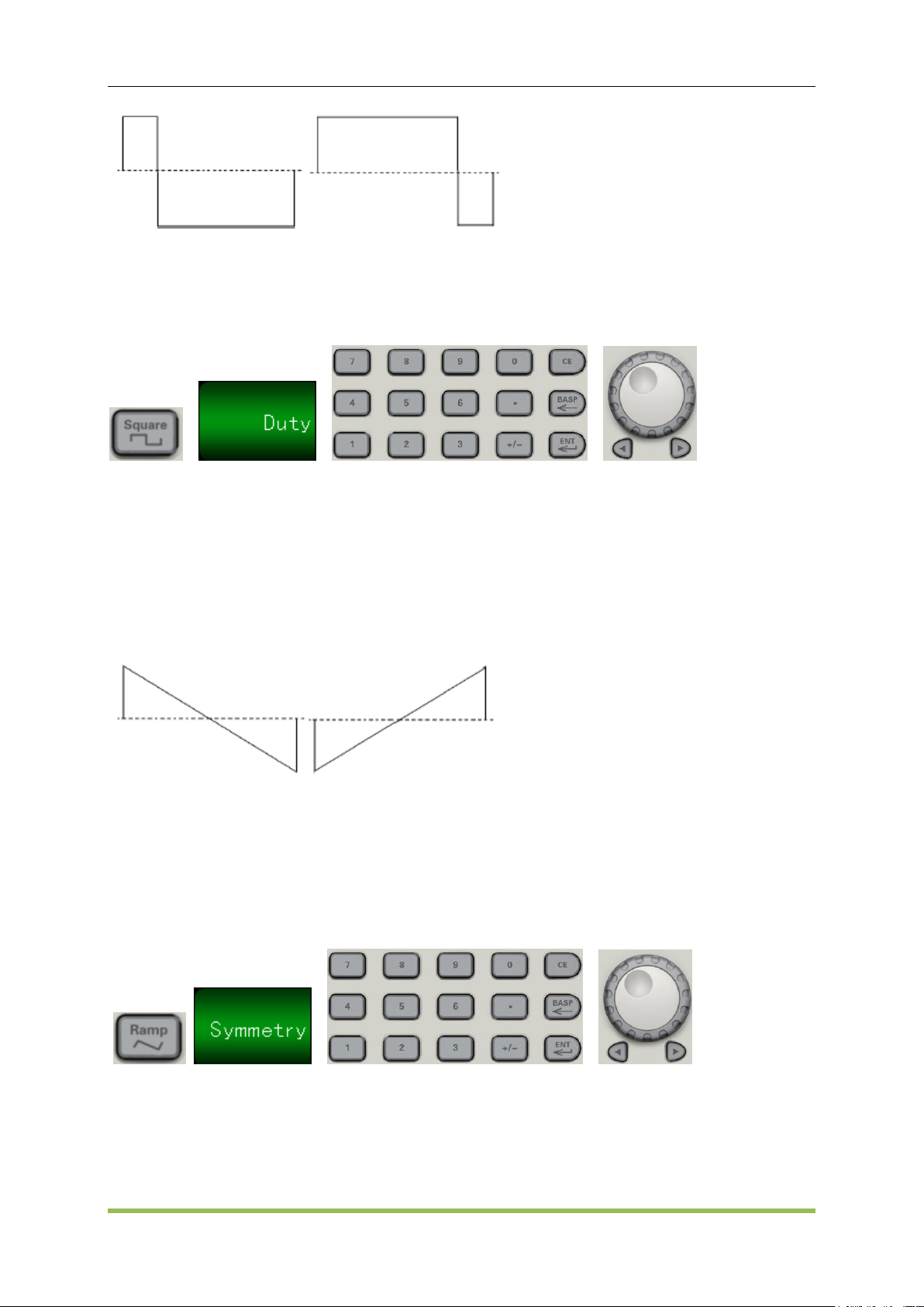
Duty Cycle (Square Waves)
A square wave’s duty cycle is the fraction of time per cycle that the waveform is at a high level.
(See Pulse Waveforms for pulse duty cycle details.)
HDG2000 Series Arbitrary Waveform Generator 27
Page 29
Features and Function
20% Duty Cycle 80% Duty Cycle
Duty Cycle: 0.001% to 99.996% at low frequencies; range reduced at higher frequency. Stored
in volatile memory; default 50%.
Front Panel:
If you use the keypad, press ENT button to finish:
SCPI:
SOURce<n>:FUNCtion:SQUare:DCYCle <percent>|MINimum|MAXimum
Symmetry (Ramp Waves)
Applies to ramp waves only. Symmetry represents the fraction of each cycle that the ramp wave is
rising.
0% Symmetry 100% Symmetry
The symmetry (default 50%) is stored in volatile memory; and is remembered when you change
to and from other waveforms.
When ramp is the modulating waveform for AM, FM, PM, or PWM, the symmetry setting does
not apply.
Front Panel:
SCPI:
SOURce<n>:FUNCtion:RAMP:SYMMetry <symmetry>|MINimum|MAXimum
SOURce<n>: FUNCtion:RAMP:SYMMetry? [MINimum|MAXimum]
HDG2000 Series Arbitrary Waveform Generator 28
Page 30
Features and Function
Voltage Autoranging
Autoranging is enabled by default and the instrument selects optimal attenuator settings.
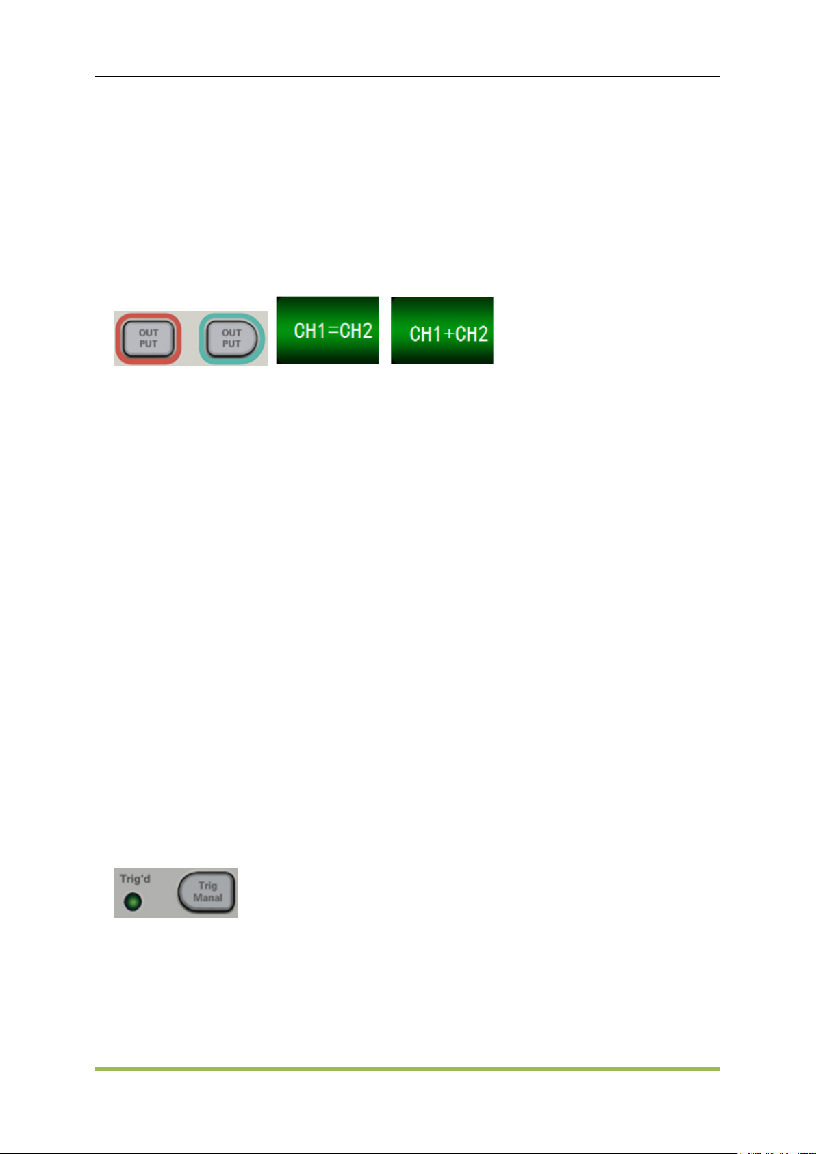
Output Control
By default, channel output is disabled at power on to protect other equipment. To enable a
channel's output, see below. When channel output is enabled, the corresponding channel button
is lit.
Front Panel:
CH1=CH2: The output signal of CH1 is the same as the output signal of CH2.
CH1+CH2: When thisbutton is on, the output signal of current channel will be the superposition
of CH1 and CH2.
SCPI:
OUTPut<n> ON|OFF,
OUTPut<n>?
Sync Output Signal
A sync output is provided on the front-panel Sync connector. All of the standard output functions
(except DC and noise) have an associated Sync signal. For applications where you may not want
to output the Sync signal, you can disable the Sync connector (Trig Menu->Syns->OFF). The
Sync signal may be derived from either output channel in the instrument.
General Behavior
By default, the Sync signal is derived from channel 1 and is routed to the Sync connector
(enabled).
When the Sync signal is disabled, the output level on the Sync connector is at a logic "low."
For sine, pulse, ramp, square, and triangle waves, the Sync signal is a square wave that is
"high" in the first half of the cycle and "low" in the last half.
The amplitude of Sync signal is not adjustable and fixed at TTL level.
Front Panel:
SCPI:
OUTPut:SYNC:SOURce CH1|CH2
HDG2000 Series Arbitrary Waveform Generator 29
Page 31
Features and Function
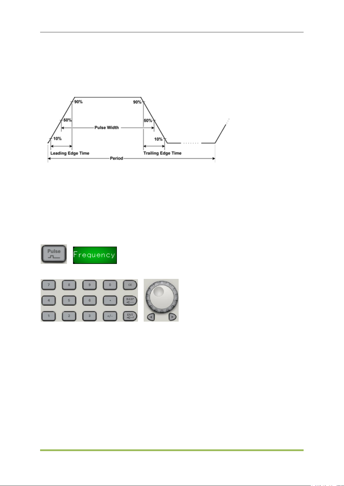
3.2 Pulse Waveforms
As shown below, a pulse or square wave consists of a period, a pulse width, a rising edge, and a
falling edge.
1. Frequency
Frequency is the number of occurrences of a repeating event per unit time. It is also referred to as
temporal frequency, which emphasizes the contrast to spatial frequency and angular frequency.
The period is the duration of one cycle in a repeating event, so the period is the reciprocal of the
frequency.Units are Uhz, mHz, Hz, KHz, MHz.
Front Panel:
Select Pulse waveform:
Select frequency instead of period:
SCPI:
SOURce<n>:FUNCtion PULSe
SOURce<n>:FREQuency<frequency>|MINimum|MAXimum
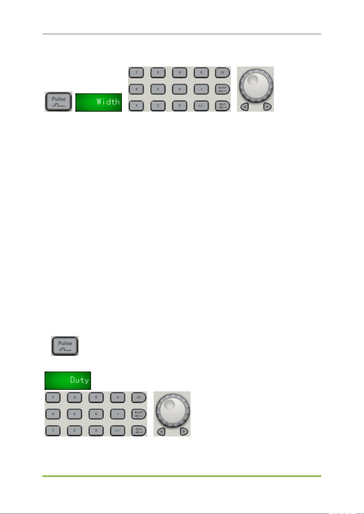
2. Pulse Width
Pulse width is the time from the 50% threshold of a pulse's rising edge to the 50% threshold of the
next falling edge.
Pulse width: 16 ns to 1,000,000 s. The default pulse width is 500 μs.
Pulse width is limited by "minimum pulse width (16 ns)" and "pulse cycle".
Pulse width ≥ minimum pulse width
Pulse width ≤ pulse cycle-2 x minimum pulse width
HDG2000 Series Arbitrary Waveform Generator 30
Page 32
Features and Function
The instrument will adjust the pulse width to accommodate the specified period.
Front Panel:
SCPI:
SOURce<n>:FUNCtion:PULSe:WIDTh <seconds>|MINimum|MAXimum
SOURce<n>:FUNCtion:PULSe:WIDTh? [MINimum|MAXimum]
For example, set pulse width of the channel 1 to 5ms:
SOURce1:FUNCtion:PULSe:WIDTh 0.005
3. Pulse Duty Cycle
The pulse duty cycle is defined as follows:
Duty Cycle = 100x (Pulse Width)/Period
Pulse width is the time from the 50% threshold of a pulse's rising edge to the 50% threshold of the
next falling edge.
Pulse duty cycle: 0.01% to 99.99% (see restrictions below). The default is 50%.
The pulse duty cycle must conform to the following restrictions determined by the minimum
pulse width (Wmin). The instrument will adjust the pulse duty cycle to accommodate the
specified period. Duty is associated with pulse width, if modify it, then pulse width will be
modified automatically. Pulse duty is limited by "minimum pulse width (16 ns)" and "pulse cycle".
Pulse duty≥100 x minimum pulse width/pulse cycle
Pulse duty≤100 x (1 - 2 x minimum pulse width/pulse cycle)
Front Panel:
Select pulse function:
Toggle to Duty:
SCPI:
SOURce<n>:PULSe:DCYCle <percent>|MINimum|MAXimum
For example, set duty of the channel 1 to 30%:
HDG2000 Series Arbitrary Waveform Generator 31
Page 33

Features and Function
SOURce1: FUNCtion: PULSe: DCYCle 30
4. Edge Times
The edge times set the transition times for the leading and trailing edges of the pulse, either
independently or together. The edge time represents the time between the 10% and 90%
thresholds.
Edge time: default 1μs.
The specified edge time must fit within the specified pulse width as shown above. The
instrument will adjust the edge time to accommodate the specified pulse width.
Front Panel:
SCPI:
SOURce<n>:FUNCtion:PULSe:TRANsition:LEADing<seconds>|MINimum|MAXimum
SOURce<n>:FUNCtion:PULSe:TRANsition:TRAiling <seconds>|MINimum|MAXimum
For example:
a) Set leading time of the channel 1 to 10ns,
SOURce1:FUNCtion:PULSe:TRANsition:LEADing 0.00000001
b) Set trailing time of the channel 1 to 10ns SOURce1:FUNCtion:PULSe:TRANsition:TRAiling
0.00000001
3.3 Amplitude Modulation (AM) and Frequency Modulation
(FM)
A modulated waveform consists of a carrier waveform and a modulating waveform. In AM, the
carrier amplitude is varied by the voltage level of the modulating waveform. In FM, the carrier
frequency is varied by the voltage level of the modulating waveform. The instrument accepts an
internal, external or external trig modulation source. One channel can modulate the other.
Select AM or FM before setting up any other modulation parameter.
To Select AM or FM
The instrument allows only one modulation mode to be enabled on a channel. When you enable
AM or FM, all other modulations are off. The two channels’ modulations are independent from one
another, and the instrument can add modulated waveforms from two channels.
The instrument will not allow AM or FM to be enabled with sweep or burst. Enabling AM or FM,
turns off sweep and burst.
HDG2000 Series Arbitrary Waveform Generator 32
Page 34

Features and Function
Function
Minimum Frequency
Maximum Frequency
Sine
1μHz
the highest frequency
Square
HDG2102B, HDG2082B,
HDG2062B, HDG2032B,
HDG2102C, HDG2072C,
HDG2052C , HDG2032C
1μHz ~ 30MHz
HDG2022B, HDG2012B,
HDG2002B
1μHz ~ the highest frequency
Ramp
HDG2102B, HDG2082B,
HDG2062B, HDG2032B,
HDG2102C, HDG2072C,
HDG2052C, HDG2032C
1μHz ~ 4MHz
HDG2022B, HDG2012B,
HDG2002B
1μHz ~ 3MHz
To avoid multiple waveform changes, enable modulation after configuring the other modulation
parameters.
Front Panel:
SCPI:
SOURce<n>:MOD ON|OFF
SOURce<n>:MOD:TYPe AM|FM
Carrier Waveform Shape
AM or FM carrier shape: Sine (default), Square, Ramp, Pulse, Ramp, Noise or Arbitrary
waveform. You cannot use DC as the carrier waveform.
For FM, the carrier frequency must always be greater than or equal to the frequency deviation.
Attempting to set a deviation greater than the carrier frequency will cause the instrument to set
the deviation equal to the carrier frequency.
The carrier frequency plus the deviation cannot exceed the selected function's maximum
frequency plus 100 kHz.
Carrier Frequency
The maximum carrier frequency varies by function, as shown below. The default is 1 kHz for all
functions.
HDG2000 Series Arbitrary Waveform Generator 33
Page 35

Features and Function
Pulse
HDG2102B, HDG2082B,
HDG2062B, HDG2032B,
HDG2022B
HDG2102C, HDG2072C,
HDG2052C , HDG2032C
1μHz ~ 15MHz
HDG2012B, HDG2002B
1μHz ~ the highest frequency
Noise
1μHz ~ the highest frequency
SCPI:
SOURce<n>:FREQuency<frequency>|MINimum|MAXimum
Modulating Waveform Shape
The instrument accepts an internal, external or external trig AM or FM modulation source.
You cannot modulate noise with noise or an arbitrary waveform with an arbitrary waveform.
The modulating waveform shape (internal source) may be:
Sine wave
Square with 50% duty cycle
UpRamp with 100% symmetry
Triangle with 50% symmetry
DnRamp with 0% symmetry
Noise - white gaussian noise
Arb - Arbitrary waveform
SCPI:
SOURce<n>:MOD:AM:INTernal:FUNCtion SINusoid|SQUare|RAMP
SOURce<n>:MOD:FM:INTernal:FUNCtion SINusoid|SQUare|RAMP
Modulating Waveform Frequency
The instrument accepts an internal, external or external trig modulation source.
Modulating frequency (internal source): varies by signal type
Modulating frequency (external source): 0 to 100 kHz.
SCPI:
SOURce<n>:MOD:AM:INTernal:FREQuency <frequency>|MINimum|MAXimum
SOURce<n>:MOD:FM:INTernal:FREQuency <frequency>|MINimum|MAXimum
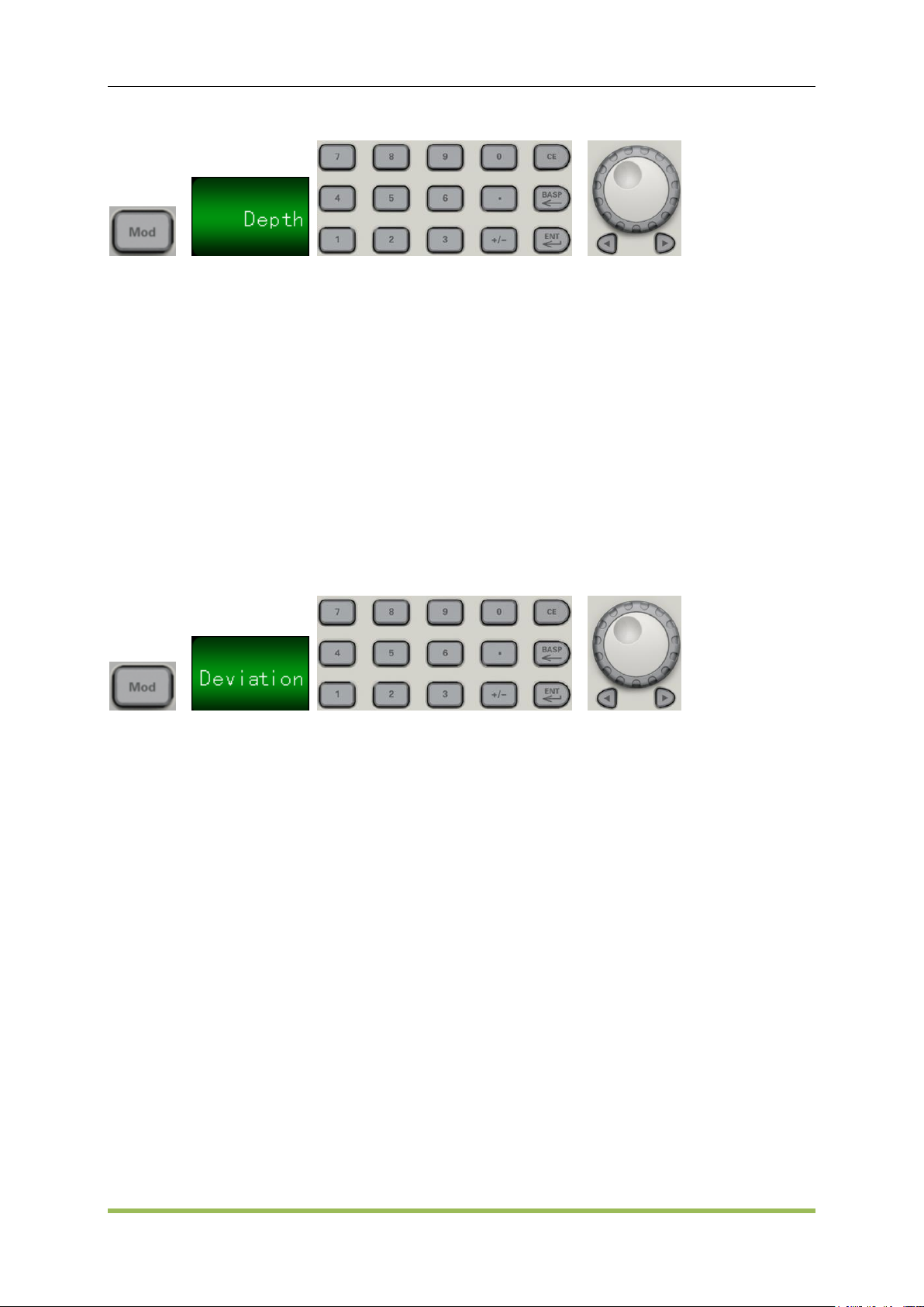
Modulation Depth (AM)
The modulation depth is a percentage that represents the amplitude variation. At 0% depth, the
amplitude is one-half of the carrier’s amplitude setting. At 100% depth, the amplitude varies
according to the modulating waveform, from 0% to 100% of the carrier’s amplitude.
Modulation depth: 0% to 120%. The default is 50%.
HDG2000 Series Arbitrary Waveform Generator 34
Page 36
Features and Function
Front Panel:
SCPI:
SOURce<n>:MOD:AM:DEPTh <depth>|MINimum|MAXimum
Frequency Deviation (FM)
The frequency deviation setting represents the peak variation in frequency of the modulated
waveform from the carrier frequency.
Frequency deviation: 1 μHz to (carrier frequency)/2, default 100 Hz.
For FM, the carrier frequency must always be greater than or equal to the frequency deviation.
Attempting to set a deviation greater than the carrier frequency will cause the instrument to set
the deviation equal to the carrier frequency.
Frequency deviation + Carrier Frequency ≤ the carrier upper frequency limit + 1 kHz
Front-Panel
SCPI:
SOURce<n>:MOD:FM:DEViation <deviation>|MINimum|MAXimum
Modulating Source
The instrument accepts an internal, external or external trig modulation source.
Modulating source: Internal (default), External, Other Channel, or External Trig. The External
modulation source may be up to 100 kHz.
With the External source, an external waveform modulates the carrier waveform. The
modulation depth (AM) or frequency deviation (FM) is controlled by the ±5 V signal level on the
front-panel MOD connector.
When the External Trig source is selected, the modulation depth (AM) or frequency deviation
(FM) is controlled by the +5 V signal level on the front-panel TRIG connector.
Front-Panel
After enabling AM or FM, select the modulating source as shown:
HDG2000 Series Arbitrary Waveform Generator 35
Page 37

Features and Function
SCPI:
SOURce<n>:MOD:AM:SOURce INTernal|EXTernal
SOURce<n>:MOD:FM:SOURce INTernal|EXTernal
3.4 Phase Modulation (PM)
A modulated waveform consists of a carrier waveform and a modulating waveform. PM is very
similar to FM, but in PM the phase of the modulated waveform is varied by the instantaneous
voltage of the modulating waveform.
To Select Phase Modulation
Only one modulation mode may be enabled at a time. Enabling PM disables the previous
modulation mode.
Enabling PM turns off sweep and burst.
Front Panel:
The waveform is output using the present carrier and modulating waveform settings.
To avoid multiple waveform changes, enable modulation after configuring the other modulation
parameters.
SCPI:
SOURce<n>:MOD ON|OFF
SOURce<n>:MOD:TYPe AM|FM|PM|ASK|FSK|PSK|PWM|BPSK
Carrier Waveform Shape
PM carrier shape: Sine (default), Square, Ramp, Pulse or Arbitrary. You cannot use Noise or DC
as the carrier waveform.
Carrier Frequency
The maximum carrier frequency varies by function, as shown below. The default is 1 kHz for all
functions. Carrier frequency must be greater than 20 times the peak modulation frequency.
HDG2000 Series Arbitrary Waveform Generator 36
Page 38

Features and Function
Modulating Waveform Shape
The instrument accepts an internal, external or external trig modulation source.
The modulating waveform shape (internal source) may be:
Sine wave
Square with 50% duty cycle
UpRamp with 100% symmetry
Triangle with 50% symmetry
DnRamp with 0% symmetry
Noise - white gaussian noise
Arb - Arbitrary waveform
SCPI:
SOURce<n>:MOD:PM:INTernal:FUNCtion SINusoid|SQUare|RAMP
Modulating Waveform Frequency
The instrument accepts an internal, external or external trig modulation source.
Modulating frequency (internal source): from 2 MHz to 500 kHz, default 100 Hz.
Front Panel:
Then enter the AM or FM frequency with the knob and keypad:
SCPI:
SOURce<n>:MOD:PM:INTernal:FREQuency <frequency>|MINimum|MAXimum
Phase Deviation
The phase deviation setting represents the peak variation in phase of the modulated waveform
from the carrier waveform. The phase deviation can be set from 0 to 360 degrees (default 180).
Front Panel:
Then set the phase deviation:
HDG2000 Series Arbitrary Waveform Generator 37
Page 39

Features and Function
SCPI:
SOURce<n>:MOD:PM:DEViation <deviation>|MINimum|MAXimum
Modulating Source
The instrument accepts an internal, external or external trig modulation source.
Modulating source: Internal (default), Other Channel, or External. The External modulation
source may be up to 100 kHz.
With the External source, the carrier waveform is modulated with an external waveform. The ±5
V signal level present on the front-panel Mod connector controls the phase deviation.
When the External Trig source is selected, the +5 V signal level present on the front-panel TRIG
connector controls the phase deviation.
Front Panel:
SCPI:
SOURce<n>:MOD:PM:SOURce INTernal|EXTernal
3.5 Frequency-Shift Keying (FSK) Modulation
You can configure the instrument to "shift" its output frequency between two preset values using
FSK modulation. The rate at which the output shifts between the two frequencies (called the
"carrier frequency" and the "hop frequency") is determined by the internal rate generator or the
signal level on thefront-panel TRIG connector.
To Select FSK Modulation
SOURce<n>:MOD ON|OFF
SOURce<n>:MOD:TYPe AM|FM|PM|ASK|FSK|PSK|PWM|BPSK
Only one modulation mode may be enabled at a time. Enabling FSK turns off the previous
HDG2000 Series Arbitrary Waveform Generator 38
Page 40

Features and Function
modulation mode.
You cannot enable FSK when sweep or burst is enabled. Enabling FSK turns off sweep and
burst.
To avoid multiple waveform changes, enable modulation after configuring the other modulation
parameters.
FSK Carrier Frequency
SOURce<n>:FREQuency<frequency>|MINimum|MAXimum
When the External source is selected, the output frequency is determined by the signal level on
the front-panel TRIG connector. When a logic low is present, the carrier frequency is output.
With a logic high level, the hop frequency is output.
FSK "Hop" Frequency
SOURce<n>:MOD:FSKey:FREQuency <frequency>|MINimum|MAXimum
The maximum alternate ("hop") frequency depends on the function. The default is 100 Hz for all
functions. The internal modulating waveform is a 50% duty cycle square wave.
Sine: 1 μHz to the highest frequency
Square: 1 μHz to the highest frequency
Ramp: 1 μHz to the highest frequency
Arb: 1 μHz to the highest frequency (except DC)
FSK Rate
SOURce<n>:MOD:FSKey:INTernal:RATE <frequency>|MINimum|MAXimum
The FSK rate is the rate at which the output frequency "shifts" between the carrier frequency and
the hop frequency using the internal FSK source.
FSK rate (internal source): 2MHz to 1 MHz, default 100 Hz.
The FSK rate is ignored when the external FSK source is selected.
FSK Source
SOURce<n>:MOD:FSKey:SOURce INTernal|EXTernal
May be internal (default), external or external trig modulation.
When the Internal source is selected, the rate at which the output frequency "shifts" between
the carrier frequency and hop frequency is determined by the FSK rate.
When the External source is selected, the output frequency is determined by the signal level on
the front-panel MOD connector.
When the External Trig source is selected, the output frequency is determined by the signal
level on the front-panel TRIG connector. When a logic low is present, the carrier frequency is
output. With a logic high level, the hop frequency is output.
Front Panel:
HDG2000 Series Arbitrary Waveform Generator 39
Page 41

Features and Function
3.6 Pulse Width Modulation (PWM)
This section discusses PWM, which stands for pulse-width modulation. PWM is only available for
the Pulse waveform, and the pulse width varies according to the modulating signal. The amount by
which the pulse width varies is called the width deviation, and it can be specified as a percentage
of the waveform period (that is, duty cycle) or in units of time.
For example, if you specify a pulse with 20% duty cycle and then enable PWM with a 5% deviation,
the duty cycle varies from 15% to 25% under control of the modulating signal.
The instrument accepts an internal, external or external trig modulation source.
To Select PWM
You cannot enable PWM when sweep or burst is enabled.
To avoid multiple waveform changes, enable modulation after configuring the other modulation
parameters.
SCPI:
SOURce<n>:MOD ON|OFF
SOURce<n>:MOD:TYPe PWM
Modulating Waveform Shape
The instrument accepts an internal, external or external trig modulation source.
The modulating waveform shape (internal source) may be:
Sine wave
Square with 50% duty cycle
UpRamp with 100% symmetry
Triangle with 50% symmetry
DnRamp with 0% symmetry
Noise - white gaussian noise
Arbitrary waveform
You can use noise as the modulating waveshape, but you cannot use noise, arbitrary
waveforms, or DC as the carrier.
Front-Panel:
HDG2000 Series Arbitrary Waveform Generator 40
Page 42

Features and Function
SCPI:
SOURce<n>:MOD:PWM:INTernal:FUNCtion SINusoid|SQUare|RAMP
Modulating Waveform Frequency
The instrument accepts an internal, external or external trig modulation source.
Modulating frequency (internal source): 2MHz to 500KHz. The default is 100 Hz.
Front Panel:
SCPI:
SOURce<n>:MOD:PWM:INTernal:FREQuency <frequency>|MINimum|MAXimum
PWM Deviation
The PWM deviation setting is the peak variation in width of the modulated pulse waveform.
SCPI:
SOURce<n>:MOD:PWM:DEViation <deviation>|MINimum|MAXimum
Modulating Source
The instrument accepts an internal, external or external trig modulation source.
Modulating source: Internal (default), external or external trig. The External modulation source
may be up to 100 kHz.
If you select the External modulating source, the deviation is controlled by the ±5 V signal level
on the front-panel MOD connector. For example, if you have set the deviation to 10%, then a +5
V signal corresponds to a 10% change in width. Lower signal levels produce less deviation.
If you select the External Trig modulating source, the deviation is controlled by the +5 V signal
level on the front-panel TRIG connector.
Front Panel:
SCPI:
SOURce<n>:MOD:PWM:SOURce INTernal|EXTernal
HDG2000 Series Arbitrary Waveform Generator 41
Page 43

Features and Function
3.7 Frequency Sweep
In frequency sweep mode, the instrument moves from the start frequency to the stop frequency at
a specified sweep rate. You can sweep up or down in frequency, with either linea. You can also
configure the instrument to output one sweep from start frequency to stop frequency by applying
an external or manual trigger. The instrument can sweep sine, square, pulse, ramp, triangle, or
arbitrary waveforms (noise and DC are not allowed).
You can specify a hold time, during which the sweep remains at the stop frequency, and a return
time, during which the frequency changes linearly from the stop frequency to the start frequency.
To Select Sweep
The instrument will not allow sweep mode to be enabled at the same time that burst or any
modulation mode is enabled. When you enable sweep, the burst or modulation mode is turned off.
To avoid multiple waveform changes, enable the sweep mode after configuring the other
parameters.
Front Panel:
Output a sweep using the present amplitude, offset, and frequency:
Press “Sweep” button to close sweep mode.
SCPI:
SOURce<n>:SWEep ON|OFF
HDG2000 Series Arbitrary Waveform Generator 42
Page 44

Features and Function
Start Frequency and Stop Frequency
The start frequency and stop frequency set the sweep’s upper and lower frequency bounds. The
sweep begins at the start frequency, sweeps to the stop frequency, and then resets back to the
start frequency.
Start and Stop frequencies: 1 μHz to the highest frequency. The sweep is phase continuous
over the full frequency range. The default start frequency is 100 Hz. The default stop frequency
is 1 kHz.
To sweep up in frequency, set the start frequency less than the stop frequency. To sweep down
in frequency, set the opposite relationship.
Each channel outputs frequency sweep or pulse sequence from corresponding BNCterminal.
Front Panel:
Center Frequency and Frequency Span
You can also set the sweep frequency boundaries of the sweep using a center frequency and
frequency span.
Center frequency: 1 μHz to 30 MHz (limited to 200 kHz for Ramps). The default is 550 Hz.
Frequency span: -30 μHz to 30 MHz (limited to 200 kHz for Ramps). The default is 900 Hz.
To sweep up in frequency, set a positive frequency span; to sweep down, set a negative
frequency span.
For sweeps with Marker Off, the Sync signal is a square waveform with a 50% duty cycle.
(missing or bad snippet) The frequency of the Sync waveform is equal to the specified sweep
time. The signal is output from the front-panel Sync connector.
For frequency sweeps with Marker On, the Sync signal is a TTL "high" at the beginning of the
sweep and a "low" at the marker frequency.
Sweep Time
Sweep time specifies the number of seconds required to sweep from the start frequency to the
stop frequency. The instrument calculates the number of points in the sweep based on the sweep
time.
Sweep time: 1 ms to300 seconds, default 1 s.
Front-Panel:
SCPI:
HDG2000 Series Arbitrary Waveform Generator 43
Page 45

Features and Function
SOURce<n>:SWEep:TIME <seconds>|MINimum|MAXimum
Hold Time and Return Time
Hold time specifies time (in seconds) to remain at the stop frequency, and return time specifies the
number of seconds to return from the stop frequency to the start frequency.
Hold time and return time: 1ms to 300 seconds (default 1s).
Front Panel:
SCPI:
SOURce<n>:SWEep:HTIMe <seconds>|MINimum|MAXimum
SOURce<n>:SWEep:RTIMe <seconds>|MINimum|MAXimum
Marker Frequency
If desired, you can set the frequency at which the signal on the front-panel Sync connector goes to
a logic low during the sweep. The Sync signal always goes from low to high at the beginning of the
sweep.
Marker frequency: between the specified start frequency and stop frequency. The default is
550 Hz.
When the sweep mode is enabled, the marker frequency must be between the specified start
frequency and stop frequency.
SCPI:
SOURce<n>:MARKer ON|OFF
SOURce<n>:MARKer:FREQuency <frequency>|MINimum|MAXimum
Sweep Trigger Source
In sweep mode, the instrument outputs a single sweep when a trigger signal is received. After one
sweep from the start frequency to the stop frequency, the instrument waits for the next trigger
while outputting the start frequency.
Sweep trigger source: Internal (default), External or Manual.
With the Internal (immediate) source, the instrument outputs a continuous sweep at a rate
HDG2000 Series Arbitrary Waveform Generator 44
Page 46

Features and Function
determined by the total of the hold time, sweep time and return time.
With the External source, the instrument accepts a hardware trigger on the rear-panel Ext Trig
connector and initiates one sweep each time Ext Trig receives a TTL pulse with the specified
polarity.
The trigger period must be greater than or equal to the specified sweep time.
With the Manual source, the instrument outputs one sweep each time the front-panel [Trigger]
key is pressed.
SCPI:
SOURce<n>:SWEep:TRIGger:SOURce INTernal|EXTernal
SOURce<n>:SWEep:TRIGger:SLOPe POSitive|NEGative
3.8 Burst Mode
The instrument can output a waveform for a specified number of cycles, called a burst. Burst is
allowed with sine, square, triangle, ramp, pulse or arbitrary waveforms (noise allowed only in
gated burst mode; DC is not allowed).
To Select Burst
Burst cannot be enabled when sweep or modulation is enabled. Enabling burst turns off sweep
and modulation.
To avoid multiple waveform changes, enable burst mode after configuring other parameters.
Front-Panel:
SCPI: SOURce<n>:BURSt ON|OFF
Burst Mode
Burst has two modes, described below. Selected mode controls allowable trigger source, and
which other burst parameters apply.
Triggered Burst Mode (N Cycle, INFinity Cycle): The instrument outputs a waveform for
specified number of cycles (burst count) each time trigger is received. After outputting specified
number of cycles, instrument stops and waits for next trigger. The instrument can use an
internal trigger to initiate burst, or you can provide external trigger by pressing the front-panel
[Trig Menu] key, applying trigger signal to front-panel TRIG connector, or sending software
trigger command from remote interface. INFinity Cycle: The instrument outputs a waveform
each time trigger is received. After outputting infinity cycle, instrument stops and waits for next
trigger.
External Gated Burst Mode: Output waveform is on or off, based on level of external signal
HDG2000 Series Arbitrary Waveform Generator 45
Page 47

Features and Function
Parameter
BURS:MODE
(BURS:MODE)
Burst Count
(BURS:NCYC)
Burst Period
(BURS:NCYC)
Burst Phase
(BURS:PHAS)
Trigger Source
(TRIG:SOUR)
Triggered Burst
Mode:
Internal Trigger
TRIGgered
Available
Available
Available
IMMediate
Triggered Burst
Mode:
External Trigger
TRIGgered
Available
Not Used
Available
EXTernal
Gated Burst
Mode:
External Trigger
GATed
Not Used
Not Used
Available
Not Used
applied to front-panel TRIG connector. When the gate signal is true, the instrument outputs a
continuous waveform. When the gate signal goes false, the current waveform cycle is
completed and the instrument stops while remaining at the voltage level corresponding to the
starting burst phase of the selected waveform. The noise waveform output stops immediately
when the gate signal goes false.
In gated mode, burst count, burst period, and trigger source are ignored.
In gated mode, you can specify polarity of signal on front-panel TRIG connector
(SOURce<n>:BURSt:TRIGger:SLOPe POSitive|NEGative). Default is Positive.
SCPI:
SOURce<n>:BURSt:MODE TRIGgered|GATed|INFinity
Burst Count
Number of cycles (1 to 100,000) to be output per burst, used in the triggered burst mode only
(internal or external source).
Number of cycles (1 to 500,000) to be output per burst. The command is valid under N Cycle.
With Internal trigger source, specified number of cycles are output continuously at a rate
determined by burst period. The burst period is the time between the starts of consecutive
bursts.
In gated burst mode, burst count is ignored.
SCPI:
SOURce<n>:BURSt:NCYCles <cycles>|MINimum|MAXimum
Burst Period
Burst period is the time from the start of one burst to the start of next burst (default 10 ms). Used in
internal triggered burst mode only. Burst period differs from "waveform frequency," which specifies
the frequency of the bursted signal.
Burst period is used only when Immediate triggering(Internal Trigger) is enabled. The burst
period is ignored when manual or external triggering is enabled (or when the gated burst mode
HDG2000 Series Arbitrary Waveform Generator 46
Page 48

Features and Function
is selected).
You cannot specify a burst period that is too short for the instrument to output with the specified
burst count and frequency. If the burst period is too short, the instrument will increase it as
needed to continuously re-trigger the burst.
Start Phase
Start phase of the burst, from 0 to +360 degrees (default 0).
Burst Trigger Source
In triggered burst mode:
The instrument outputs a waveform of the specified number of cycles (burst count) when a
trigger received. After the specified number of cycles have been output, the instrument stops
and waits for next trigger.
Internal: the instrument outputs continuously when burst mode is enabled.
EXTernal: the instrument accepts a hardware trigger at the front-panel TRIG connector. The
instrument outputs one burst of the specified number of cycles each time TRIG receives a TTL
pulse with the proper polarity (SOURce<n>:BURSt:TRIGger:SLOPe POSitive|NEGative).
External trigger signals during a burst are ignored.
EXTernal or BUS: burst count and burst phase remain in effect, but burst period is ignored.
SCPI:
SOURce<n>:BURSt:TRIGger:SOURce INTernal|EXTernal
Gate Polarity
Select the gate as high level or low level on the front panel EXT BNC connector to output burst
sequence.
SCPI:
SOURce<n>:BURSt:GATE:POLarity NORMal|INVerted
SOURce<n>:BURSt:GATE:POLarity?
Set gate polarity to inverted on CH1: SOURce1:BURSt:GATE:POLarity INVerted
3.9 Trigger System
This section describes the instrument's triggering system.
Trigger Overview
This triggering information applies to sweep and burst only. You can issue triggers for sweeps or
bursts using internal triggering, external triggering, timer triggering, or manual triggering.
Internal (default): instrument outputs continuously when sweep or burst mode is selected.
External: uses front-panel TRIG connector to control sweep or burst. The instrument initiates
HDG2000 Series Arbitrary Waveform Generator 47
Page 49

Features and Function
one sweep or outputs one burst each time TRIG receives a TTL pulse. You can select whether
instrument triggers on rising or falling edge.
Manual: triggering initiates one sweep or outputs one burst each time you press [Trig Menu] on
the front panel.
Trigger Sources
This triggering information applies to sweep and burst only. You must specify the source from
which the instrument accepts a trigger.
Sweep and Burst trigger source: Immediate (default), External, Manual.
The instrument will accept a manual trigger, a hardware trigger from the front-panel TRIG
connector, or continuously output sweeps or bursts using an internal trigger.
Trigger source setting is volatile;
SCPI:
SOURce<n>:SWEep:TRIGger:SOURce INTernal|EXTernal
SOURce<n>:BURSt:TRIGger:SOURce INTernal|EXTernal
Immediate Triggering
Internal trigger mode (default): instrument continuously outputs sweep or burst (as specified by
sweep time or burst period).
SCPI:
SOURce<n>:BURSt:TRIGger
SOURce<n>:SWEep:TRIGger
Manual Triggering
Manual trigger mode: you manually trigger the instrument by pressing [Trig Menu] key. The
instrument initiates one sweep or burst for each time you press [Trig Menu]. The led of button is lit
when you are in the trigger menu and the instrument is waiting for a manual trigger. The led of this
button blinks when the instrument is waiting for a manual trigger, but you are not in the trigger
menu.
External Triggering
In external trigger mode, the instrument accepts a hardware trigger at the front-panel TRIG
connector. The instrument initiates one sweep or burst each time Ext Trig receives a TTL pulse
with the specified edge. The external trigger mode is like the manual trigger mode except that you
apply the trigger to the TRIG connector.
SCPI:
SOURce<n>:SWEep:TRIGger:SOURce EXTernal
SOURce<n>:SWEep:TRIGger:SLOPe POSitive|NEGative
SOURce<n>:BURSt:TRIGger:SOURce EXTernal
SOURce<n>:BURSt:TRIGger:SLOPe POSitive|NEGative
HDG2000 Series Arbitrary Waveform Generator 48
Page 50

Waveform Generation Tutorial
Chapter4 Waveform Generation Tutorial
Generation of A Sine Wave Function
Generation of A Square Wave Function
Generation of A Ramp Wave Function
Generation of A Pulse Wave Function
Generation of A Noise Wave Function
Generation of An Arb. Wave Function
Generation of A Harmonic Wave Function
Method of input params
Mode Waveform
Digital Generator
HDG2000 Series Arbitrary Waveform Generator 49
Page 51

Waveform Generation Tutorial
The series signal generator can output kinds of standard Functions. For example: Sine wave,
square wave, ramp wave, pulse, noise wave, DC signal, sinc, exp fall, lorentz, gause, haver sine,
Dual Tone, ECG.
Frequncy
Frequency is the number of occurrences of a repeating event per unit time. It is also referred to as
temporal frequency, which emphasizes the contrast to spatial frequency and angular frequency.
The period is the duration of one cycle in a repeating event, so the period is the reciprocal of the
frequency. Units are μHz, mHz, Hz, KHz, MHz.
Period
Frequency is the number of occurrences of a repeating event per unit time. It is also referred to as
temporal frequency, which emphasizes the contrast to spatial frequency and angular frequency.
The period is the duration of one cycle in a repeating event, so the period is the reciprocal of the
frequency. Units are s, ms, μs, ns.
Amplitude
The amplitude of a periodic variable is a measure of its change over a single period. Units are Vpp,
mVpp, μVpp.
DC Offset
When describe a periodic function in the frequency domain, DC offset is the mean value of the
waveform.
High Level/ Low Level
The signal level value of the maximum value is signals of high level. The minimum value is low
level, units are V, mV, μV etc.
Phase
Unit is degree. The starting phase range can be set from 0 ° to 360 °. The default phase value of
0 °.
Duty
Duty is the pulse duration and pulse ratio of total cycle. Unit is %, the default value is 50%.
Symmetry
Symmetry is defined as a percentage of triangular wave rise time and period.
Symmetry range can be set from 0% to 100%. The default value is 50%.
HDG2000 Series Arbitrary Waveform Generator 50
Page 52

Waveform Generation Tutorial
Pulse Width
Pulse Width is the time interval between the %50 threshold of the pulse rising amplitude and the
50% threshold of the pulse falling amplitude. Pulse duty ratio is defined as the percentage of the
pulse width of pulse cycle. Symmetry range can be set from 0% to 100%. The default value is
50%.
Leading Time
It is defined as the response curves from the steady state value of 10% to 90% steady state value.
Trialing Time
It is defined as the response curves from the steady state value of 90% to 10% steady state value
4.1 Generation of A Sine Wave Function
Sine wave is a wave with single frequency. It is named as Sine according to the sine graph. Any
complex signal can be seen as a signal combined by different sine wave with different frequency,
amplitude.
Please follow these steps to output sine wave:
1. Press Sine button in the front panel, if the waveform is setting as <modulation mode>, <sweep
mode> or <burst mode>, please turn off the mode;
2. Press channel output button in the front panel to open channel waveform output switch, then the
button is lighting;
3. Oscilloscope shows sine wave.
4. Modify the waveform <Frequency>. One way is to press frequency/cycle shortcut key F/T button
in the front panel. Another way is to press F1 button when it displays the main menu of the sine
wave. Then the selected parameter is highlighted.
5. Modify the waveform <Amplitude>. One way is to press AMP shortcut key in the front panel.
Another way is to press F2 button when it display main menu of the sine wave. Then the selected
parameter is highlighted.
6. Modify the waveform <DC OFFSET>. One way is to press Offset shortcut key in the front panel.
Another way is to press F3 button when it displays main menu of the sine wave. Then the selected
parameter is highlighted.
7. Modify the waveform <Phase>, the way is to press F4 button when it displays main menu of the
sine wave. Then the selected parameter is highlighted.
8. To set the same phase between channel 1 and channel 2, please press F5 button when it
displays main menu of the sine wave.
9. To change the parameters after being highlighted, user can use the front panel knobs and
digital keyboard to input parameter values. Please refer to the <Method of inputting parameters>.
HDG2000 Series Arbitrary Waveform Generator 51
Page 53

Waveform Generation Tutorial
4.2 Generation of A Square Wave Function
Square wave is a non-sinusoidal waveform. There are only "high" and "low" the two values for an
ideal square wave.
Please follow these steps to output square wave:
1. Press Square wave button in the front panel, and if the waveform is setting as <modulation
mode>, <sweep mode> or <burst mode>, please turn off the mode;
2. Press channel output button in the front panel to open channel waveform output switch, then the
button is lighting;
3. Oscilloscope shows Square wave.
4. Modify the waveform <Duty>, the way is to press F5 button when it displays main menu of the
square wave. Then the selected parameter is highlighted.
5. Modify other parameters, please refer to <Generation Of A Sine Wave Function>
6. To change the parameters after being highlighted, user can use the front panel knobs and
digital keyboard to input parameter values. Please refer to the <Method of inputting parameters>.
7. To set the same phase between channel 1 and channel 2, please press F5 button when it
displays main menu of the square wave.
4.3 Generation of A Ramp Wave Function
Ramp wave is non-sinusoidal waveforms.
Please follow these steps to output ramp wave:
1. Press Ramp wave button in the front panel, and the waveform is setting as <modulation mode>,
<sweep mode> or <burst mode>, please turn the mode off;
2. Press channel output button in the front panel to open channel waveform output switch, then the
button is lighting;
3. Oscilloscope shows ramp wave.
4. To modify the waveform <Symmetry>, the way is to press F5 button when it displays main menu
of the square wave. Then the selected parameter is highlighted.
5. To modify other parameters, please refer to <Generation Of A Sine Wave Function>.
6. To change the parameters after being highlighted, use can use front panel knobs and digital
keyboard to input parameter values. Please refer to the <Method of inputting parameters>.
7. To set the same phase between channel 1 and channel 2, please press F5 button when it
displays main menu of the ramp wave.
HDG2000 Series Arbitrary Waveform Generator 52
Page 54

Waveform Generation Tutorial
4.4 Generation of A Pulse Wave Function
Please follow these steps to output Pulse wave.
1. Press Pulse wave button in the front panel, and if the waveform is setting as <modulation
mode>, <sweep mode> or <burst mode>, please turn the mode off;
2. Press channel output button in the front panel open channel waveform output switch, then the
button is lighting;
3. Oscilloscope shows pulse wave.
4. To modify the waveform <Leading Time>, the way is press F6 button to enter page 2 of main
menu, then press F2 button. Then the selected parameter is highlighted.
5. To modify the waveform <Tailing Time>, the way is press F6 button to enter page 2 of main
menu, then press F2 button twice when at the main menu of the square wave, then the selected
parameter is highlighted.
6. To modify the waveform <Pulse Width>, the way is press F6 button to enter page 2 of main
menu, then press F1 button when at the main menu of the square wave. Then the selected
parameter is highlighted.
7. To modify the waveform <Duty>, the way is Press F6 button to enter page 2 of main menu, then
press F1 button twice when at the main menu of the square wave. Then the selected parameter is
highlighted.
8. To change the parameters after being highlighted, user can use the front panel knobs and
digital keyboard to input parameter values. Please refer to the <Method of inputting parameters>.
9. To make the channel with another channel phase alignment, press F5 button when it displays
the main menu of the pulse wave.
10. To modify other parameters, please refer to <Generation Of A Sine Wave Function>
4.5 Generation of A Noise Wave Function
Noise can only in a continuous mode;
Please follow these steps to output a noise wave.
1. Press Noise wave button in the front panel;
2. Press channel output button in the front panel open channel waveform output switch, then the
button is lighting;
3. Oscilloscope shows noise wave.
4. To change the parameters after being highlighted, user can use the front panel knobs and
digital keyboard to input parameter values. Please refer to the <Method of inputting parameters>.
HDG2000 Series Arbitrary Waveform Generator 53
Page 55

Waveform Generation Tutorial
5. To modify other parameters, please refer to <Generation Of A Sine Wave Function>
Note: Not do modulation and frequency sweep for noise wave.
4.6 Generation of An Arb. Wave Function
Please follow these steps to output arb wave:
1. Press Arb wave button in the front panel, and if the waveform is setting as <modulation mode>,
<sweep mode> or <burst mode>, please turn the mode off;
2. The default waveform for Arbitrary wave is DC wave, To modify the current type of arbitrary
wave,when in the main menu of the arbitrary wave, press F6 to enter page 2 of the menu, press
the F2 key to enter wave type submenu, then use F1 to F6 function keys to select the waveform
and press the F0 key to return to the main menu;
3. Press channel output button in the front panel to open channel waveform output switch, then the
button is lighting;
4. Oscilloscope shows arb wave.
5. To modify other parameters, please refer to <Generation Of A Sine Wave Function>
6. To change the parameters after being highlighted, user can use the front panel knobs and
digital keyboard to input parameter values. Please refer to the <Method of inputting parameters>.
7. If <User-Defined Waveforms> is choosed, browse the machine internal dev (FLASH device) or
an external storage device (<Usb Storage Device> or<SD card>), choose the waveform file suffix
for hwf.
8. If <User-Defined Waveforms> is choosed, the <Sampling Frequency of Arbitrary Wave> and
<Magnification Of Arbitrary Wave> params can be modified.
Note: user-defined waveform file can be generated by itself or using other tools.
4.7 Generation of A Harmonic Wave Function
Please follow these steps to output harmonic wave.
1. Press Harmonic wave button in the front panel, and if the waveform is setting as <modulation
mode>, <sweep mode> or <burst mode>, please turn the mode off;
2. Press channel output button in the front panel open channel waveform output switch, then the
button is lighting;
3. To modify the order of the <Harmonic Wave>, press F4 button when in the harmonic wave
menu, then the button is lighting. Use the knob and digital keyboard to modify parameter values;
HDG2000 Series Arbitrary Waveform Generator 54
Page 56

Waveform Generation Tutorial
4. Specify the index of the Harmonic Wave order, press the F1 button when in the harmonic wave
menu, then the button is lighting. Use the knob and digital keyboard to modify parameter values;
5. To modify the amplitude of specific harmonic wave, press F2 button when it displays harmonic
wave menu, resulting of lighting on the buttons;
6. To modify the phase of specific harmonic wave, press F3 button. When in the harmonic wave
menu, then the button is lighting;
7. To modify the effective harmonic wave, press F5 button to select desired type in the harmonic
wave menu.
8. Oscilloscope shows harmonic wave.
9. To change the parameters after being highlighted, user can use the front panel knobs and
digital keyboard to input parameter values. Please refer to the <Method of inputting parameters>.
4.8 Method of input params
There are two methods
1. Input by digital keypad in the front panel. Input the params to the dialog showed and choose
units to confim or choose cancel to cancel.
2. Input by knob button and direction buttons. Select bit in the params by direction buttons and
increase or deincrease the value of the bit using konb button.
4.9 Mode Waveform
AM
Amplitude Modulation. AM make the high frequency carrier signal amplitude changes over
modulation signal's instantaneous value.
FM
Frequency Modulation. Frequency modulation represent information to the change of
instantaneous frequency of the carrier wave.
PM
Phase Modulation. PM is a form of modulation that represents information as variations in the
instantaneous phase of a carrier wave
ASK
Amplitude Shift Keying. ASK is a form of amplitude modulation that represents digital data as
HDG2000 Series Arbitrary Waveform Generator 55
Page 57

Waveform Generation Tutorial
variations in the amplitude of a carrier wave.
ASK uses a finite number of amplitudes, each assigned a unique pattern of binary digits. Usually,
each amplitude encodes an equal number of bits.
FSK
Frequency-shift keying.is a frequency modulation scheme in which digital information is
transmitted through discrete frequency
changes of a carrier wave.[1] The simplest FSK is binary FSK (BFSK).
BFSK uses a pair of discrete frequencies to transmit binary (0s and 1s) information.
[2] With this scheme, the "1" is called the mark frequency and the "0" is called the space frequency
PSK
PSK phase shift keying.is a digital modulation scheme that conveys data by changing, or
modulating, the phase of a reference signal (the carrier wave).
Any digital modulation scheme uses a finite number of distinct signals to represent digital data.
PSK uses a finite number of phases, each assigned a unique pattern of binary digits.
BPSK
Binary Phase Shift Keying.BPSK (also sometimes called PRK, phase reversal keying, or 2PSK) is
the simplest form of phase shift keying (PSK).
It uses two phases which are separated by 180°.
Signal Wave
In <modulation mode>, the signal wave is used to modulate the carrier signal waveform. It's
source can ether be internal or be external.
The Shape of the Signal Wave should be choosed, when the source is inernal. Except Noise and
Dc, Other wave can be Signal Wave.
Carrier
It is a waveform (usually sinusoidal) or sine wave that is modulated (modified) with an input signal
for the purpose of conveying information.[1] This carrier wave is usually a much higher frequency
than the input signal
Modulation Depth
It indicates how much the modulation varies around its "original" level. It's range is from 0% to
120%.
Frequency Deviation
It is used in FM radio to describe the maximum instantaneous difference between an FM
HDG2000 Series Arbitrary Waveform Generator 56
Page 58

Waveform Generation Tutorial
modulated frequency and the nominal carrier frequency.
It must be less equal he nominal carrier frequency and the sum of the Frequency Deviation and
carrier frequency must be less equal the sum of the max of the type carrier and 10KHz.
Phase Deviation
It indicates by how much the modulated variable varies around its unmodulated level.
Duty Deviation
Duty Deviation and pulse width Deviation is modulated resulting in the variation of the average
value of the waveform. Its range is from 0 to 500ks. It must be less than the Pusle width and be
limited with min pusle width and leading or trialing time.
PWM
Pulse Width Modulation. PWM is a modulation technique that conform the width of the pulse,
formally the pulse duration, based on modulator signal information.
Shift Keying Rate
Shift Keying Rate is the rate of the shift.
Hopping Frequncy
It is used in FSK as a rate of carrier frequncy changes.
4.10 Digital Generator
1. Terminal Description:
Vcc: 3.3V
2. Function Introduction
Please press “Utility” button, and use knob or cursor arrows to select “Digital Generator” function
interface.
HDG2000 Series Arbitrary Waveform Generator 57
Page 59

Waveform Generation Tutorial
Programmable Signal: Users can edit digital signal.
Sync Signal: Output Synchronized signal of CH1.
OFF: Turn off
1)Programmable Signal
User can set the following parameters for the programmable signal.
Mode: Cycle and Step
Size: Set the number of programmable signal
Internal: In cycle mode, the internal time between a signal and the other.
Index: Index of signal
Value: Set 16bit digital signal value
For example,
Mode, Size, Interval and Index set to Cycle, 3, 2s and 3. And set the three digital signals to
0000000000000001, 0000000000000011, 0000000000000111 in turn. After completing setting for
a signal, please press ENT button to confirm and save it. Then the three digital signals will output
in turn and periodically.
HDG2000 Series Arbitrary Waveform Generator 58
Page 60

In cycle mode, signals will output in turn.
Waveform Generation Tutorial
If setting Mode to “Step”, then press “Step” softkey on page 2/2. A signal will output when you
press “Step” softkey each time.
HDG2000 Series Arbitrary Waveform Generator 59
Page 61

2)Sync Signal
Waveform Generation Tutorial
1. Select function to sync singal.
2. Select the sync signal source to CH1 (or CH2).
3. Open CH1 waveform output, Select the Signal Type to "Sine ", frequency to “1KHz”, Amplitude
to 1V,Y Offset to 0V.
4. Connect Digital Generator Terminals to LOGIC Analyzer Terminals to measure. The output
signal of D0-D15 terminals is a square waveform (3.3V, peak- to- peak).
HDG2000 Series Arbitrary Waveform Generator 60
Page 62

SCPI Programming Reference
Chapter5 SCPI Programming Reference
Introduction to the SCPI Language
Alphabetical List of SCPI Commands and Queries
Programming Examples
HDG2000 Series Arbitrary Waveform Generator 61
Page 63

SCPI Programming Reference
5.1 Introduction to the SCPI Language
The following four symbols are not the content of SCPI commands and will not be sent with the
commands, but are usually used to describe the parameters in the commands.
Braces { }
The parameters enclosed in braces are optional and can be ignored.
Vertical Bar |
The vertical bar is used to separate multiple parameters and one of the parameters must be
selected when sending the command.
Triangle Brackets < >
The parameter enclosed in the triangle brackets must be replaced by an effective value.
Square Brackets [ ]
The content (parameter or keyword) enclosed in the square brackets can be omitted. When the
parameter is omitted, the instrument will set the parameter to its default.
SCPI (Standard Commands for Programmable Instruments) is an ASCII-based instrument
command language designed for test and measurement instruments. SCPI commands are based
on a hierarchical structure, also known as a tree system. In this system, associated commands are
grouped together under a common node or root, thus forming subsystems. A portion of the
OUTPut subsystem is shown below to illustrate the tree system.
Syntax Conventions
The format used to show commands is illustrated below:
SOURce<n>:VOLTage <amplitude>|MINimum|MAXimum
SOURce<n>:FREQuency:CENTer {<frequency>|MINimum|MAXimum}
The command syntax shows most commands (and some parameters) as a mixture of upper- and
lower-case letters. The upper-case letters indicate the abbreviated spelling for the command. For
shorter program lines, you can send the abbreviated form. For better program readability, you can
send the long form.
For example, in the above syntax statement, VOLT and VOLTAGE are both acceptable forms.
You can use upper- or lower-case letters. Therefore, VOLTAGE, volt, and Volt are all acceptable.
Other forms, such as VOL and VOLTAG, are not valid and will generate an error.
Braces ( { } ) enclose the parameter choices for a given command string. The braces are not
sent with the command string.
A vertical bar ( | ) separates multiple parameter choices for a given command string. The bar is
not sent with the command string.
Triangle brackets in the second example ( < > ) indicate that you must specify a value for the
enclosed parameter. For example, the above syntax statement shows the <frequency>
parameter enclosed in triangle brackets. The brackets are not sent with the command string.
You must specify a value for the parameter (for example "FREQ:CENT 1000") unless you
select another option shown in the syntax (for example "FREQ:CENT MIN").
Some syntax elements (for example nodes and parameters) are enclosed in square brackets
HDG2000 Series Arbitrary Waveform Generator 62
Page 64

SCPI Programming Reference
([ ]). This indicates that the element is optional and can be omitted. The brackets are not sent
with the command string. If you do not specify a value for an optional parameter, the
instrument chooses a default value.
Command Separators
A colon ( : ) is used to separate a command keyword from a lower-level keyword. You must insert
a blank space to separate a parameter from a command keyword.
Using the MIN andMAX Parameters
For many commands, you can substitute "MIN" or "MAX" in place of a parameter. For example,
consider the following command:
SOURce<n>:VOLTage:OFFSet <offset>|MINimum|MAXimum
Instead of selecting a specific value for the <offset> parameter, you can substitute MIN to set the
offset to its minimum value, MAX to set the offset to its maximum value.
SCPI Command Terminators
A command string sent to the instrument must terminate with a <new line> (<NL>) character. The
IEEE-488 EOI(End-Or-Identify) message is interpreted as a <NL> character and can be used to
terminate a command string in place of a <NL> character. A <carriage return> followed by a <NL>
is also accepted. Command string termination will always reset the current SCPI command path to
the root level.
IEEE-488.2 Common Commands
The IEEE-488.2 standard defines a set of common commands that perform functions such as
reset, self-test, and status operations. Common commands always begin with an asterisk ( * ), are
three characters in length, and may include one or more parameters. The command keyword is
separated from the first parameter by a blank space. Use a semicolon ( ; ) to separate multiple
commands as shown below:
*RST; *CLS; *ESE 32; *OPC?
SCPI Parameter Types
The SCPI language defines several data formats to be used in program messages and response
messages.
Numeric Parameters
Commands that require numeric parameters will accept all commonly used decimal
representations of numbers including optional signs, decimal points, and scientific notation.
Special values for numeric parameters such as MIN and MAX are also accepted. You can also
send engineering unit suffixes with numeric parameters (e.g., M, k, m, or u). If a command accepts
only certain specific values, the instrument will automatically round the input numeric parameters
to the accepted values. The following command requires a numeric parameter for the frequency
HDG2000 Series Arbitrary Waveform Generator 63
Page 65

SCPI Programming Reference
value:
SOURce<n>:FREQuency:CENTer <frequency>|MINimum|MAXimum
Discrete Parameters
Discrete parameters are used to program settings that have a limited number of values (like
IMMediate, EXTernal). They may have a short form and a long form just like command keywords.
You can mix upper- and lower-case letters.
Boolean Parameters
Boolean parameters represent a single binary condition that is either true or false. For a false
condition, the instrumentwill accept "OFF". For a true condition, the instrument will accept "ON".
ASCII String Parameters
String parameters can contain virtually any set of ASCII characters. A string must begin and end
with matching quotes; either with a single quote or a double quote. You can include the quote
delimiter as part of the string by typing it twice without any characters in between.
HDG2000 Series Arbitrary Waveform Generator 64
Page 66

SCPI Programming Reference
5.2 Alphabetical List of SCPI Commands and Queries
AM Subsystem
ASK Subsystem
BPSK Subsystem
BURSt Subsystem
CALibration Subsystem
DATA Subsystem
DISPlay Subsystem
FM Subsystem
FREQuency Subsystem
FSKey Subsystem
FUNCtion Subsystem
HARMonic Subsystem
IEEE-488.2 Common Commands
MARKer Subsystem
MEMory Subsystem
MMEMory Subsystem
OUTPut Subsystem
PHASe Subsystem
PM Subsystem
PSK Subsystem
PWM Subsystem
SOURce Subsystem
SWEep Subsystem
SYSTem Subsystem
VOLTage Subsystem
HDG2000 Series Arbitrary Waveform Generator 65
Page 67
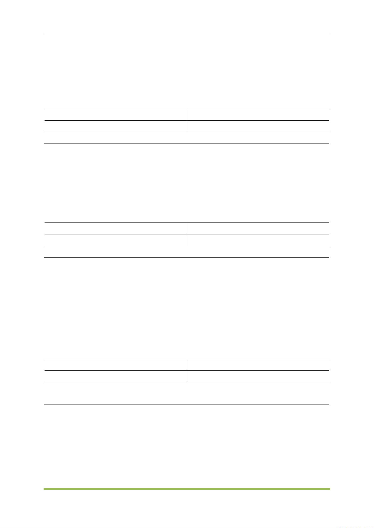
SCPI Programming Reference
Parameter
Typical Return
0% to 120%, default 50%
+5.000000000000000E+01
Set the modulation of CH1 to 50%: SOURce1:MOD:AM:DEPTh 50
Parameter
Typical Return
2 mHz to 500 kHz
+1.000000000000000E+02
Set the modulation frequency of CH1 100Hz:SOURce1:MOD:AM:INTernal:FREQuency 100
Parameter
Typical Return
SINusoid|SQUare|RAMP, default SINusoid
SINusoid, SQUare, or RAMP
Select a square wave as the modulating waveform of CH1:
SOURce1:MOD:AM:INTernal:FUNCtion SQUare
5.2.1 AM Subsystem
The AM subsystem allows you to add amplitude modulation (AM) to a carrier waveform.
SOURce<n>:MOD:AM:DEPTh <depth>|MINimum|MAXimum
SOURce<n>:MOD:AM:DEPTh? [MINimum|MAXimum]
To achieve modulation depth greater than 100%, output carrier amplitude may be reduced.
With AM:SOURce EXTernal, carrier waveform is modulated with an external waveform.
SOURce<n>:MOD:AM:INTernal:FREQuency <frequency>|MINimum|MAXimum
SOURce<n>:MOD:AM:INTernal:FREQuency? [MINimum|MAXimum]
Set frequency of modulating waveform. The waveform chosen as modulating source will operate
at that frequency, within waveform frequency limits.
When you select an arbitrary waveform as the modulating source, the frequency changes to
the frequency of the arbitrary waveform, which is based on the sample rate and the number of
points in the arbitrary waveform.
This command should be used only with the internal modulation source (AM:SOURce
INTernal).
SOURce<n>:MOD:AM:INTernal:FUNCtion SINusoid|SQUare|RAMP
SOURce<n>:MOD:AM:INTernal:FUNCtion?
Selects shape of modulating waveform.
This command should be used only with the internal modulation source (AM:SOURce
INTernal).
Pulse and DC cannot be carrier waveform for AM.
SOURce<n>:MOD:AM:SOURce INTernal|EXTernal
SOURce<n>:MOD:AM:SOURce?
HDG2000 Series Arbitrary Waveform Generator 66
Page 68

SOURce<n>:MOD:FM:SOURce INTernal|EXTernal
Parameter
Typical Return
INTernal|EXTernal, default INTernal
INTernal, or EXTernal
Select external modulation source of CH1: SOURce1:MOD:AM:SOURce EXTernal (could also
substituteASK, FM, BPSK, FSK, PM, PSAK or PWM for AM)
Parameter
Typical Return
ON|OFF, default OFF
ON, or OFF
Enable modulation: SOURce1:MOD ON
Parameter
Typical Return
TYPe AM|FM|PM|ASK|FSK|PSK|PWM|BPSK,
default AM
AM, FM, PM, ASK, FSK, PSK, PWM or BPSK
Set FM modulation: SOURce<n>:MOD:TYPe FM
SOURce<n>:MOD:FM:SOURce?
SOURce<n>:MOD:PM:SOURce INTernal|EXTernal
SOURce<n>:MOD:PM:SOURce?
SOURce<n>:MOD:ASKey:SOURce INTernal|EXTernal
SOURce<n>:MOD:ASKey:SOURce?
SOURce<n>:MOD:FSKey:SOURce INTernal|EXTernal
SOURce<n>:MOD:FSKey:SOURce?
SOURce<n>:MOD:PSKey:SOURce INTernal|EXTernal
SOURce<n>:MOD:PSKey:SOURce?
SCPI Programming Reference
SOURce<n>:MOD:BPSKey:INTernal:RATE <frequency>|MINimum|MAXimum
SOURce<n>:MOD:PWM:SOURce INTernal|EXTernal
SOURce<n>:MOD:PWM:SOURce?
Select the source of the modulating signal.
SOURce<n>:MOD ON|OFF
SOURce<n>:MOD?
Enables or disables modulation.
SOURce<n>:MOD:TYPe AM|FM|PM|ASK|FSK|PSK|PWM|BPSK
SOURce<n>:MOD:TYPe?
Select modulation type
HDG2000 Series Arbitrary Waveform Generator 67
Page 69

SCPI Programming Reference
Parameter
Typical Return
0 Vpp to20 Vpp, default 2Vpp
+1.000000000000000E+00
Set the modulating amplitude to 1Vp-p for CH1:SOURce1:MOD:ASKey:AMPLitude 1
Parameter
Typical Return
2 mHz to 1 MHz, default 100Hz
+2.000000000000000E+02
Set the modulating rate to 200Hz on CH1: SOURce1:MOD:ASKey:INTernal:RATE 200
Parameter
Typical Return
INTernal|EXTernal, default INTernal
INTernal, or EXTernal
Select external modulation source on CH1: SOURce<n>:MOD:ASKey:SOURce EXTernal
Parameter
Typical Return
POSitive|NEGative, default POSitive
POSitive, or NEGative
Select NEGative of the modulating signal to control waveform output:
SOURce1:MOD:ASKey:POLarity NEGative
To avoid multiple waveform changes, enable modulation after configuring the other modulation
parameters.
Only one modulation mode may be enabled at a time.
The instrument will not enable modulation with sweep or burst enabled. When you enable
modulation, the sweep or burst mode is turned off.
PWM is allowed only when pulse is the selected function.
5.2.2 ASK Subsystem
ASK(Amplitude Shift Keying) is a form of amplitude modulation that represents digital data as
variations in the amplitude of a carrier wave.
SOURce<n>:MOD:ASKey:AMPLitude <amplitude>|MINimum|MAXimum
SOURce<n>:MOD:ASKey:AMPLitude? [MINimum|MAXimum]
Sets amplitude of the modulating waveform
SOURce<n>:MOD:ASKey:INTernal:RATE <frequency>|MINimum|MAXimum
SOURce<n>:MOD:ASKey:INTernal:RATE? [MINimum|MAXimum]
Set the output frequency between carrier frequency and frequency hopping rate of "mobile".
SOURce<n>:MOD:ASKey:SOURce INTernal|EXTernal
SOURce<n>:MOD:ASKey:SOURce?
Select the source of the modulating signal (INTernal or EXTernal).
SOURce<n>:MOD:ASKey:POLarity POSitive|NEGative
SOURce<n>:MOD:ASKey:POLarity?
Select POSitive or NEGative of the modulating signal to control waveform output.
HDG2000 Series Arbitrary Waveform Generator 68
Page 70

SCPI Programming Reference
Parameter
Typical Return
2 mHz to 1 MHz, default 100Hz
+2.000000000000000E+02
Set BPSK rate to 200Hz: SOURce1:MOD:BPSKey:INTernal:RATE 200
Parameter
Typical Return
0to 360 degrees, default 180 degrees
+0.000000000000000E-00
Set phase shift to 90 degrees: SOURce1:MOD:BPSKey:PHASe 90
5.2.3 BPSK Subsystem
The BPSK subsystem allows you to modulate a wave form with Binary Phase Shift Keying (BPSK),
a digital modulation format. In BPSK, the carrier waveform is phase shifted between two phase
settings using an on/off keying. The source may be internal, using a square wave at a specified
frequency, or external, using the external trigger input.
SOURce<n>:MOD:BPSKey:INTernal:RATE <frequency>|MINimum|MAXimum
SOURce<n>:MOD:BPSKey:INTernal:RATE? [MINimum|MAXimum]
Sets the rate at which the output phase "shifts" between the carrier and offset phase.
The BPSK rate is used only when the INTernal source is selected (BPSK:SOURce INTernal)
and is ignored when the EXTernal source is selected (BPSK:SOURce EXTernal).
The internal modulating waveform is a square wave with a 50% duty cycle.
SOURce<n>:MOD:BPSKey:PHASe <phase>|MINimum|MAXimum
SOURce<n>:MOD:BPSKey:PHASe ? [MINimum|MAXimum]
Sets the Binary Phase Shift Keying phase shift in degrees.
5.2.4 BURSt Subsystem
This section describes the BURSt subsystem.
Burst Modes
There are two burst modes, described below. The instrument enables one burst mode at a time.
Triggered Burst Mode (default): The instrument outputs a waveform for a number of cycles
(burst count) each time a trigger is received. After outputting the specified number of cycles, the
instrument stops and waits for the next trigger. You can configure the instrument to use an
internal trigger to initiate the burst or you can provide an external trigger by pressing the
front-panel [Trig Menu] key, by applying a trigger signal to the front-panel TRIG connector, or
by sending a software trigger command from the remote interface.
External Gated Burst Mode: The instrument output is either "on" or "off" based on the level of
the external signal applied to the front-panel TRIG connector. When this signal is true, the
instrument outputs a continuous waveform. When this signal goes false, the current waveform
cycle is completed and then the instrument stops while remaining at the voltage corresponding
HDG2000 Series Arbitrary Waveform Generator 69
Page 71

SCPI Programming Reference
Parameter
Typical Return
NORMal|INVerted, default NORMal
NORMal, or INVerted
Select INVerted for an externally gated burst: SOURce1:BURSt:GATE:POLarity INVerted
Parameter
Typical Return
TRIGgered|GATed|INFinity, default TRIGgered
TRIGgered, GATed, or INFinity
Set gated burst mode: SOURce<n>:BURSt:MODE GATed
Parameter
Typical Return
1 to 1 000 000(External or manual trigger);
1 to 500 000(Internal), only for N cycle;
Default 1
+5.000000000000000E+00
Return number of cycles per burst: SOURce1:BURSt:NCYCles 5
to the starting burst phase of the waveform.
The following table shows which modes are associated with which burst features.
SOURce<n>:BURSt:GATE:POLarity NORMal|INVerted
SOURce<n>:BURSt:GATE:POLarity?
Selects NORMal or INVerted logic levels on the front-panel TRIG connector for an externally gated
burst.
SOURce<n>:BURSt:MODE TRIGgered|GATed|INFinity
SOURce<n>:BURSt:MODE?
Selects the burst mode.
TRIGgered: the instrument outputs a waveform for a number of cycles (burst count) each time a
trigger is received from the trigger source (SOURce<n>:BURSt:TRIGger:SOURce).
In GATed burst mode, the output waveform is on or off, based on the signal at the rear-panel
TRIG connector. Select this signal's polarity using SOURce<n>:BURSt:TRIGger:SLOPe
POSitive|NEGative. When the gate signal is true, the instrument outputs a continuous
waveform.
GATed: burst count, burst period, and trigger source are ignored (these are used for the
triggered burst mode only). I
SOURce<n>:BURSt:NCYCles <cycles>|MINimum|MAXimum
SOURce<n>:BURSt:NCYCles? [MINimum|MAXimum]
Sets the number of cycles to be output per burst (triggered burst mode only).
SOURce<n>:BURSt ON|OFF
SOURce<n>:BURSt?
Enables or disables burst mode.
HDG2000 Series Arbitrary Waveform Generator 70
Page 72

SCPI Programming Reference
Parameter
Typical Return
ON|OFF, default OFF
ON or OFF
Enable burst mode: SOURce1:BURSt ON
Parameter
Typical Return
POSitive|NEGative, default POSitive
POSitive or NEGative
Select NEGative of the external trigger signal to start sweep output:
SOURce<n>:BURSt:TRIGger:SLOPe NEGative
Parameter
Typical Return
none
0( pass) or +1( fail)
Calibrate using the current value: CALibration?
Parameter
Typical Return
Whole number, 1 to 8
none
Prepare for calibration step 5: CALibration:SETup 5
Output phase is set to 0 when burst is enabled.
To avoid multiple waveform changes, enable the burst mode after configuring the other burst
parameters.
The instrument will not allow the burst mode to be enabled at the same time that sweep or any
modulation mode is enabled. When you enable burst, the sweep or modulation mode is turned
off.
SOURce<n>:BURSt:TRIGger:SLOPe POSitive|NEGative
SOURce<n>:BURSt:TRIGger:SLOPe?
Select POSitive or NEGative of the external trigger signal to start sweep output.
5.2.5 CALibration Subsystem
The CALibration subsystem is used to calibrate the instrument.
CALibration:SETup <step>
CALibration?
CALibration:VALue <value>
CALibration:STORe
CALibration?
Performs a calibration using the calibration value (CALibration:VALue).
CALibration:SETup should always precede the CALibration? query.
Modifies the volatile version of the calibration constants. Use CALibration:STORe to save these
constants in nonvolatile memory at end of calibration.
CALibration:SETup <step>
Configures the calibration step to be performed.
HDG2000 Series Arbitrary Waveform Generator 71
Page 73
SCPI Programming Reference
Parameter
Typical Return
none
无
Store calibration constants into non-volatile memory: CAL:STOR
Parameter
Typical Return
Numeric, default 0
none
-
Parameter
Typical Return
ON|OFF, default OFF
ON , or OFF
COUNter ON
Parameter
Typical Return
Current frequency or counter
This setting is non-volatile; it will not be changed by power cycling or *RST.
CALibration:STORe
Takes calibration constants in volatile memory (CALibration?), and places them in nonvolatile
memory, where they will not be changed by power cycle.
CALibration:VALue <value>
Specifies the value of the known calibration signal.
This setting is non-volatile; it will not be changed by power cycling or *RST.
5.2.6 COUNter Subsystem
COUNter ON|OFF
COUNter:MEASure?
COUNter:GATEtime
COUNter:GATEtime?
COUNter:TYPE
COUNter ON|OFF
Enable or disable frequency meter.
COUNter:MEASure?
Get current counter measurement value.
COUNter:GATEtime AUTO|USER1|USER2|USER3|USER4|USER5|USER6
COUNter:GATEtime?
Set GATEtime
HDG2000 Series Arbitrary Waveform Generator 72
Page 74

Parameter
Typical Return
AUTO AUTO
USER1 1 ms
USER2 10 ms
USER3 100 ms
USER4 1 s
USER5 10 s
USER6 >10 s
AUTO, USER1, USER2, USER3, USER4, USER5,
or USER6
Parameter
Typical Return
LF_COUNTER|LF_FREQ|HF_COUNTER
|HF_FREQ, default LF_COUNTER
LF_COUNTER, LF_FREQ|HF_COUNTER, or
HF_FREQ
Parameter
Typical Return
<addr> Hexadecimal number, from 0x00to 64M, 4Byte
none
<dots_num> Decimal number
<binary_block> Binary number, dots_num*2 byte, starting as “#”
<value> Integer, from -32767 to +32767
Parameter
Typical Return
<addr> Hexadecimal number, from 0x00to 64M, 4Byte
无
<dots_num> Decimal number
<binary_block> Binary number, dots_num*4 byte, starting as “#”
<value> Integer, from -1 to +1
COUNter:TYPE LFCOUNTER|LFFREQ|HFCOUNTER|HFFREQ
Set counter type.
SCPI Programming Reference
5.2.7 DATA Subsystem
The DATA subsystem manages user-defined arbitrary waveforms.
SOURce<n>:DATA:DAC16 <addr>,<dots_num>,<binary_block>| <value>,<value>, . . .
Download data (.dac format) to ddr2
SOURce<n>:DATA: <addr>,<dots_num>,<binary_block>| <value>,<value>, . . .
Download data (float format) to ddr2
SOURce<n>:DATA:OUTPut <start_addr>,<end_addr>
Output data in specified address.
SOURce<n>:DATA:DAC16 <addr>,<dots_num>,<binary_block>| <value>,<value>, . . .
SOURce<n>:DATA: <addr>,<dots_num>,<binary_block>| <value>,<value>, . . .
HDG2000 Series Arbitrary Waveform Generator 73
Page 75

SOURce<n>:DATA:OUTPut <start_addr>,<end_addr>
Parameter
Typical Return
<start_addr> Hexadecimal number, from 0x00to 64M, 4Byte
<end_addr> Hexadecimal number, from 0x00to 64M, 4Byte
Parameter
Typical Return
1%至 100%, default 50%
80%
DISPlay:BRIGhtness 80
Parameter
Typical Return
ON|OFF, default ON
ON, or OFF
Enable display saver: DISPlay:SAVer:STATe ON
Parameter
Typical Return
Default 500Hz
+1.000000000000000E+03
Set peak frequency deviation to 1 kHz: SOURce1:MOD:FM:DEViation 1000
5.2.8 DISPlay Subsystem
The DISPlay subsystem controls the instrument's display.
DISPlay:BRIGhtness <brightness>|MINimum|MAXimum
DISPlay:BRIGhtness? [MINimum|MAXimum]
Set the display bringhtness.
SCPI Programming Reference
DISPlay:SAVer ON|OFF
DISPlay:SAVer ?
Enable or disable display saver.
5.2.9 FM Subsystem
SOURce<n>:MOD:FM:DEViation <deviation>|MINimum|MAXimum
SOURce<n>:MOD:FM:DEViation? [MINimum|MAXimum]
Sets the peak frequency deviation in Hz.
The deviation cannot exceed the carrier frequency. If you attempt to set a deviation that
exceeds the carrier frequency (with FM enabled), the instrument will adjust the deviation to
the maximum value allowed for that carrier frequency.
The carrier frequency plus the deviation cannot exceed the selected function's maximum
frequency plus 100 kHz. If you attempt to set the deviation to an invalid value, the instrument
adjusts it to the maximum value allowed with the present carrier frequency.
If the deviation causes the carrier waveform to exceed a frequency boundary for the current
HDG2000 Series Arbitrary Waveform Generator 74
Page 76

SCPI Programming Reference
Parameter
Typical Return
2 mHz to 500 kHz, default 100Hz
+5.000000000000000E+02
Set the modulating frequency to 500Hz: SOURce1:MOD:FM:INTernal:FREQuency 500
Parameter
Typical Return
SINusoid|SQUare|RAMP, default SINusoid
SINusoid, SQUare, or RAMP
Select a squarewave as the modulating waveform: SOURce1:MOD:FM:INTernal:FUNCtion
SQUare
duty cycle (square waveform only), the instrument will adjust the duty cycle to the maximum
value allowed with the present carrier frequency.
If you select the External modulating source, the deviation is controlled by the ±5 V signal
level on the rear-panel Modulation In connector.For example, if the frequency deviation is
100 kHz, then a +5 V signal level corresponds to a 100 kHz increase in frequency.Lower
external signal levels produce less deviation and negative signal levels reduce the frequency
below the carrier frequency.
Deviation is valid under these conditions:
deviation≤carrier frequency
deviation + carrier frequency≤ carrier upper frequency limit + 1 kHz
SOURce<n>:MOD:FM:INTernal:FREQuency <frequency>|MINimum|MAXimum
SOURce<n>:MOD:FM:INTernal:FREQuency? [MINimum|MAXimum]
Sets the frequency of the modulating waveform. The modulating source waveform operates at that
frequency, within the frequency limits of that waveform.
When you select an arbitrary waveform as the modulating source, the frequency changes to the
frequency of thearbitrary waveform, which is based on the sample rate and the number of
points in the arbitrary waveform.
This command should be used only with the internal modulation source (FM:SOURce INTernal).
SOURce<n>:MOD:FM:INTernal:FUNCtion SINusoid|SQUare|RAMP
SOURce<n>:MOD:FM:INTernal:FUNCtion?
This command selects the shape of the modulating waveform.
This command should be used only with the internal modulation source (FM:SOURce INTernal).
5.2.10 FREQuency Subsystem
The FREQuency subsystem sets the instrument's output frequency
SOURce<n>:FREQuency<frequency>|MINimum|MAXimum
SOURce<n>:FREQuency? [MINimum|MAXimum]
HDG2000 Series Arbitrary Waveform Generator 75
Page 77

SCPI Programming Reference
Parameter
Typical Return
Different waveform has diffenent frequency
range, please refer to Output Configuration
and Appendix B
+1.000000000000000E+03
Set output frequency to 100 Hz: SOURce1:FREQuency 100
Parameter
Typical Return
Different waveform has diffenent frequency
range, please refer to Output Configuration
and Appendix B
Default 550Hz
+1.000000000000000E+03
Set sweep center frequency to 1 kHz: SOURce1:FREQuency:CENTer 1000
Parameter
Typical Return
please refer to Output Configuration and
Appendix B Default 100Hz
+2.000000000000000E+02
Set “hopping” rate to 200Hz on CH1: SOURce1:MOD:FSKey:FREQuency 200
Parameter
Typical Return
2 mHz to 1 MHz, default 100Hz
+2.000000000000000E+02
Set moding rate to 200Hz on CH1: SOURce1:MOD:FSKey:INTernal:RATE 200
Sets the output frequency
SOURce<n>:FREQuency:CENTer <frequency>|MINimum|MAXimum
SOURce<n>:FREQuency:CENTer? [MINimum|MAXimum]
Sets the center frequency. Used with frequency span for a frequency sweep.
The following equation shows how span relates to start and stop frequencies.
Frequency Span = Stop Frequency + Start Frequency
The following equation shows how center frequency relates to start and stop frequencies.
Center Frequency = (|Stop Frequency + Start Frequency|)/2
5.2.11 FSKey Subsystem
FSKey subsystem sets the FSK waveform.
SOURce<n>:MOD:FSKey:FREQuency <frequency>|MINimum|MAXimum
SOURce<n>:MOD:FSKey:FREQuency? [MINimum|MAXimum]
Set the FSK alternating frequency (or "hopping").
SOURce<n>:MOD:FSKey:INTernal:RATE <frequency>|MINimum|MAXimum
SOURce<n>:MOD:FSKey:INTernal:RATE? [MINimum|MAXimum]
Set the ‘moving’ rate of output frequency between carrier frequency and hopping frequency.
HDG2000 Series Arbitrary Waveform Generator 76
Page 78

SCPI Programming Reference
Parameter
Typical Return
SINusoid|SQUare|RAMP|
PULSe|NOISe|DC|SINC|EXPFall|HAVErsine
|LOREntz| DUALtone|GAUSe|
ECG| USER| HARMonic|, default SINusoid
SINusoid, SQUare, RAMP, PULSe, NOISe, DC,
SINC, EXPFall、HAVErsine, LOREntz,
DUALtone, GAUSe, ECG, USER, or HARMonic|
Set output on channel 1 to sine: SOURce1:FUNCtion SINusoid
FSK rate should be used only with the internal modulation source(FSK:SOURce INTernal).
5.2.12 FUNCtion Subsystem
The FUNCtion subsystem configures the instrument's output function:
SOURce<n>:FUNCtion <wave>
output waveform
SOURce<n>:FUNCtion:ARBitrary <filename>
Output arbitrary waveform file
SOURce<1|2>:FUNCtion:ARBitrary:PTPeak
peak-to-peak voltage for an arbitrary waveform
SOURce<1|2>:FUNCtion:ARBitrary:SRATe
sample rate for arbitrary waveform
SOURce<n>:FUNCtion:SQUare:DCYCle
pulse duty cycle for pulse
SOURce<n>:FUNCtion:RAMP:SYMMetry
symmetry percentage for ramp
SOURce<n>:FUNCtion:PULSe:DCYCle
pulse duty cycle for pulse
SOURce<n>:FUNCtion:PULSe:WIDTh
pulse width
SOURce<n>:FUNCtion:PULSe:TRANsition:LEADing
Leading edge time for pulse
SOURce<n>:FUNCtion:PULSe:TRANsition:TRAiling
Trailing edge time for pulse
SOURce<n>:FUNCtion <wave>
SOURce<n>:FUNCtion?
Selects output function
NOISe generates white gaussian noise
ARB generates the arbitrary waveform currently selected by FUNCtion:ARBitrary.
SOURce<n>:FUNCtion:ARBitrary <filename>, SOURce<n>:FUNCtion:ARBitrary?
HDG2000 Series Arbitrary Waveform Generator 77
Page 79

SCPI Programming Reference
Parameter
Typical Return
Effective filename: including user-defined file
and built-in waveform file; Common use:
”INT:/Builtin/SINC.hwf”,"INT:/Mywave.hwf","
SD:/mywave.hwf","USB:/mywave.hwf"
File name
Set arbitrary filename output: INT:/Builtin/SINC.hwf SOURce1:FUNCtion:ARBitrary
"INT:/Builtin/SINC.hwf", return Int:/Builtin/SINC.hwf
Parameter
Typical Return
Discrete values 1,4,5,20, default 1V
+4.000000000000000E+00
Set peak to peak voltage to 4 V: SOURce1:FUNCtion:ARBitrary:PTPeak 4
Parameter
Typical Return
From 1 to 255, default 1
+2.500000000000000E+07
Set sample rate on CH1 to25MSa/s: SOURce1:FUNCtion:ARBitrary:SRATe 10
Parameter
Typical Return
0.001% to 99.996%,limited as described
below, default 50%
+3.000000000000000E+01
Set duty cycle to 30%: SOURce1:FUNCtion:SQUare:DCYCle 30
Parameter
Typical Return
0% to 100%, default 50%
+3.000000000000000E+01
Set symmetry on CH1 to 30%: SOURce1:FUNCtion:RAMP:SYMMetry 30
SOURce<1|2>:FUNCtion:ARBitrary:PTPeak <voltage>|MINimum|MAXimum,
SOURce<1|2>:FUNCtion:ARBitrary:PTPeak?{MINimum|MAXimum}
Sets peak to peak voltage.
SOURce<1|2>:FUNCtion:ARBitrary:SRATe {<sample_rate>|MINimum|MAXimum},
SOURce<1|2>:FUNCtion:ARBitrary:SRATe? {MINimum|MAXimum}
Sets the sample rate for the arbitrary waveform.
sample rate = 250M/(4*n)
n: the setting value by user
When n is 0, the sample rate is 250M.
SOURce<n>:FUNCtion:SQUare:DCYCle <percent>|MINimum|MAXimum,
SOURce<n>:FUNCtion:SQUare:DCYCle? [MINimum|MAXimum]
Sets pulse duty cycle.
SOURce<n>:FUNCtion:RAMP:SYMMetry <symmetry>|MINimum|MAXimum,
SOURce<n>:FUNCtion:RAMP:SYMMetry? [MINimum|MAXimum]
Sets the symmetry percentage for ramp waves.
HDG2000 Series Arbitrary Waveform Generator 78
Page 80

SCPI Programming Reference
Parameter
Typical Return
0 % to 100%, default 50%
+3.000000000000000E+01
Set duty cycle on CH1 to 30%: SOURce1:FUNCtion:PULSe:DCYCle 30
Parameter
Typical Return
16ns to 1000μs, default 500μs
+5.000000000000000E-03
Set pulse width on CH1 to 5 ms: SOURce1:FUNCtion:PULSe:WIDTh 0.005
SOURce<n>:FUNCtion:PULSe:DCYCle <percent>|MINimum|MAXimum
SOURce<n>:PULSe:DCYCle? [MINimum|MAXimum]
Sets pulse duty cycle.
The FUNCtion:PULSe:DCYCle and FUNCtion:PULSe:WIDTh commands affect the same
parameter.
The pulse duty cycle is defined as:
Duty Cycle = 100 x Pulse Width ÷ Period
Pulse width is the time from the 50% threshold of a pulse's rising edge to the 50% threshold of
the next falling edge.
The pulse duty cycle range is 0 percent to 100 percent. However, the pulse duty cycle is limited
by minimum pulse width and edge time restrictions, which prevent you from setting exactly 0
percent or 100 percent. For example, for a 1 kHz pulse waveform, you are typically restricted to
pulse duty cycles in the range 0.002 percent to 99.998 percent, limited by the minimum pulse
width of 16 ns.
Restrictions Based on Pulse Width: The specified pulse duty cycle must conform to the following
restrictions determined by the minimum pulse width (Wmin).
Duty Cycle ≥ (Wmin / Period) X 100
Duty Cycle ≤ (1 – Wmin / Period) X 100
SOURce<n>:FUNCtion:PULSe:WIDTh <seconds>|MINimum|MAXimum
SOURce<n>:FUNCtion:PULSe:WIDTh? [MINimum|MAXimum]
Sets pulse width.
The FUNCtion:PULSe:DCYCle and FUNCtion:PULSe:WIDTh commands affect the same
parameter.
Pulse width is the time from the 50% threshold of a pulse's rising edge to the 50% threshold of
the next falling edge.
Pulse Width ≥ Wmin
Pulse Width ≤ Period - 2 x Wmin
SOURce<n>:FUNCtion:PULSe:TRANsition:LEADing<seconds>|MINimum|MAXimum
SOURce<n>:PULSe:TRANsition:LEADing? [MINimum|MAXimum]
SOURce<n>:FUNCtion:PULSe:TRANsition:TRAiling <seconds>|MINimum|MAXimum
HDG2000 Series Arbitrary Waveform Generator 79
Page 81

SCPI Programming Reference
Parameter
Typical Return
Default 1μs
+1.000000000000000E-08
Set leading edge time on CH1 to 10 ns: SOURce1:FUNCtion:PULSe:TRANsition:LEADing
0.00000001
Set trailing edge time on CH1 to 10 ns: SOURce1:FUNCtion:PULSe:TRANsition:TRAiling
0.00000001
Parameter
Typical Return
<sn> integer, 2 to 16, default 2;
<value>Continuous real Numbers
none
Sets the amplitude of the second harmonic to 1Vpp on CH1: SOURce1:HARMonic:AMPL 2,1
Parameter
Typical Return
<sn> integer, 2 to 16, default 2;
<value>Continuous real Numbers, 0 to
360degrees, default 0
+9.000000000000000E+01
Set the second Harmonic phase on CH1 to 90 degrees: SOURce1:HARMonic:PHASe 2,90
SOURce<n>:PULSe:TRANsition:TRAiling? [MINimum|MAXimum]
Sets the pulse edge time on the leading, trailing, or both edges of a pulse.
The leading edge time applies to rising edge, and represents the time from the 10% threshold
to the 90% threshold of the edge; the trailing edge represents the time from the 90% threshold
to the 10% threshold.
The specified edge time must fit within the specified pulse width and period. The instrument will
limit the edge time to accommodate the specified pulse width or duty cycle.
5.2.13 HARMonicSubsystem
SOURce<n>:HARMonic:AMPL –Harmonic amplitude
SOURce<n>:HARMonic:PHASe –Harmonic phase
SOURce<n>:HARMonic:ORDEr –Harmonic order
SOURce<n>:HARMonic:TYPe –Harmonic type
SOURce<n>:HARMonic:AMPL <sn>,<value>|MINimum|MAXimum
SOURce<n>:HARMonic:AMPL?
Set Harmonic amplitude
SOURce<n>:HARMonic:PHASe <sn>,<value>|MINimum|MAXimum
SOURce<n>:HARMonic:PHASe? <sn>[,MINimum|MAXimum]
Set Harmonic phase.
HDG2000 Series Arbitrary Waveform Generator 80
Page 82

SOURce<n>:HARMonic:ORDEr <value>|MINimum|MAXimum
Parameter
Typical Return
2 to the highest frequency ÷fundamental
frequency, ,integer, Max 16, default 2
+8.000000000000000E+00
Set Harmonic order on CH1 to 8: SOURce1:HARMonic:ORDEr 8
Parameter
Typical Return
EVEN|ODD|ALL, default ALL
EVEN, ODD, or ALL
Set harmonic type on CH1 to odd: SOURce1:HARMonic:HARMonic:TYPe ODD
Parameter
Typical Return
none
Return factory, model, series number andvesion
Return the instrument's identification string: *IDN?
Parameter
Typical Return
none
none
Reset the instrument: *RST
SOURce<n>:HARMonic:ORDEr? [MINimum|MAXimum]
Set Harmonic order.
SOURce<n>:HARMonic:TYPe EVEN|ODD|ALL|USER
SOURce<n>:HARMonic:TYPe?
Select Harmonic type even, odd or all.
SCPI Programming Reference
5.2.14 IEEE-488 Common Commands
*IDN? - Instrument identification
*RCL/*SAV - Recall/save instrument state
*RST - Reset instrument to factory defaults
*TRG - Trigger command, command is valid under sweep mode and burst mode
*TST? - Self-test
*IDN?
Identification Query. Returns instrument’s identification string.
*RST
Resets instrument to factory default state.
Does not affect stored instrument states, stored arbitrary waveforms, or I/O settings; these are
stored in non-volatile memory.
HDG2000 Series Arbitrary Waveform Generator 81
Page 83

SCPI Programming Reference
Parameter
Typical Return
ON|OFF, default OFF
ON, or OFF
Enable sweep marker on CH1: SOURce1:MARKer ON
Parameter
Typical Return
Any frequency between start and stop frequency,
default 550 Hz
+1.000000000000000E+03
Set marker frequency to 1000Hz:SOURce2:MARKer:FREQuency 1000
Parameter
Typical Return
USER1|USER2|USER3|USER4|USER5
none
Delete the contents of storage location 1: MEM:STAT:DEL USER1?
5.2.15 MARKer Subsytem
SOURce<n>:MARKer –Enable or disable sweep marker function
SOURce<n>:MARKer:FREQuency -Sets the marker frequency
SOURce<n>:MARKer ON|OFF
SOURce<n>:MARKer?
Enable or disable sweep marker function.
SOURce<n>:MARKer:FREQuency <frequency>|MINimum|MAXimum
SOURce<n>:MARKer:FREQuency? [MINimum|MAXimum]
Sets the marker frequency.
5.2.16 MEMory Subsystem
MEMory:STATe:DELete USER1|USER2|USER3|USER4|USER5
Deletes a state storage location
5.2.17 MMEMory Subsystem
The MMEMory subsystem manages the file system in the instrument or on an external USB file
system. The file system can store and load several file formats.
Commands and Queries
The MMEMory subsystem includes the following commands and queries.
MMEMory:CATalog? - lists available and used space and files on Mass Memory device
MMEMory:CDIRectory - changes to a directory
MMEMory:COPY -copies a file on Mass Memory device
HDG2000 Series Arbitrary Waveform Generator 82
Page 84
SCPI Programming Reference
Parameter
Typical Return
String with a string of double quotes, limited to
256 characters.
(none)
MMEMory:CDIRectory "SD:/tmp
Parameter
Typical Return
Both files can be any valid file name
(none)
MMEMory:COPY "SD:/tmp","tmp1.hsf"
Parameter
Typical Return
Any valid file name, including file
extension.
(none)
Delete the indicated file from the root directory of the internal flash file system:
MMEMory:DELete "Int:/tmp.hsf"
Parameter
Typical Return
Any valid file name on current mass
no
MMEMory:DELete -removes files from Mass Memory device
MMEMory:LOAD:STATe-loads saved instrument state from file
MMEMory:MDIRectory -makes a new directory (folder)
MMEMory:RDIRectory -removes a directory
MMEMory:STORe:STATe -stores instrument state to file
MMEMory:CATalog?
Returns a list of all files in the current mass storage directory, including internal storage and the
USB drive.
MMEMory:CDIRectory <folder>
MMEMory:CDIRectory?
Amend the current path to < directory_name > specified path
ASCII type, String with a string of double quotes, limited to 256 characters
MMEMory:COPY <folder>,<file_name>
Copies a file from < folder > to < file_name >(not current path).
<folder> ASCII type, String with a string of double quotes, limited to 256 characters.
<file_name> String with double quotation (including suffix), limited to 40 characters.
MMEMory:DELete <file_name>
Deletes a file. To delete a folder, use MMEMory:RDIRectory.
MMEMory:LOAD:STATe <file_name>
MMEMory:STORe:STATe <file_name>
Loads or saves a complete instrument setup, using a named file on the mass storage.
HDG2000 Series Arbitrary Waveform Generator 83
Page 85

SCPI Programming Reference
storage directory, including file extension.
Load a complete instrument setup from the file in internal mass memory:
MMEMory:LOAD:STATe "Int:/tmp.hsf"
Store instrument setup to the root directory of the internal flash file system:
MMEMory:STORe:STATe "Int:/tmp.hsf"
Parameter
Typical Return
Any directory name, including the mass
storage unit specifier, default INT:\
String with a string of double quotes, limited
to 256 characters.
"INT:\"
MMEMory:RDIRectory
MMEMory:MDIRectory "test"
Parameter
Typical Return
ON|OFF, default OFF
ON, or OFF
Enable output connector for channel 1: OUTPut1 ON
Parameter
Typical Return
CH1|CH2, default CH1
ON or OFF
Disable front panel Sync connector for CH1: OUTPut:SYNC:SOURce CH1
MMEMory:RDIRectory <folder>
MMEMory:MDIRectory <folder>
MMEMory:MDIRectory makes a new directory (folder) on the mass storage medium.
MMEMory:RDIRectory removes a directory (folder) on the mass storage medium.
5.2.18 OUTPut Subsystem
The OUTPut subsystem controls the front-panel channel output and Sync connectors:
OUTPut<n> - front-panel channel output connector state
OUTPut:SYNC - front-panel Sync connector state
OUTPut<n> ON|OFF,
OUTPut<n>?
Enables or disables the front-panel output connector.
When output is enabled, the front-panel channel output key is illuminated.
OUTPut changes the state of the channel output connector by switching the output relay,
without zeroing output voltage.
OUTPut:SYNC:SOURce CH1|CH2
Disables or enables the front-panel Sync connector.
HDG2000 Series Arbitrary Waveform Generator 84
Page 86

SCPI Programming Reference
Parameter
Typical Return
0 to 360degrees, default 0
+9.0000000000000E+01
Set channel 1 phase offset to 90 degrees: SOURce1:PHASe 90
Parameter
Typical Return
none
none
Reset all phase generators: PHAS:SYNC
Parameter
Typical Return
0 to 360degrees, default 180degrees
+9.000000000000000E+01
Set phase deviation to 90 degrees: SOURce1:MOD:PM:DEViation 90
5.2.19 PHASeSubsystem
The PHASe subsystem allows you to adjust the waveform phase; this is useful in
channel-to-channel and channel-to- ync applications. This subsystem also allows you to use the
10 MHz Out and 10 MHz In rear-panel connectors to synchronize multiple instruments.
SOURce<n>:PHASe -sets phase offset of output waveform (not available for arbitrary waveforms
or noise)
SOURce<n>:PHASe:SYNChronize -synchronizes phase of both internal channels on a
two-channel instrument.
SOURce<n>:PHASe <phase>|MINimum|MAXimum
SOURce<n>:PHASe? [MINimum|MAXimum]
Sets waveform's phase offset angle.
Use PHASe:SYNChronize to synchronize the phases of the two internal channels.
SOURce<n>:PHASe:SYNChronize
Simultaneously resets all phase generators in the instrument to establish a common, internal
phase zero reference point.
SOURce1 and SOURce2 mean nothing for this command.
The setting is invalid when any channel is in a modulation mode in two channels.
5.2.20 PM Subsystem
The PM subsystem allows you to phase modulate a waveform.
SOURce<n>:MOD:PM:DEViation <deviation>|MINimum|MAXimum
SOURce<n>:MOD:PM:DEViation? [MINimum|MAXimum]
Sets the phase deviation in degrees. This value represents the peak variation in phase of the
modulated waveform from the carrier waveform.
HDG2000 Series Arbitrary Waveform Generator 85
Page 87
SCPI Programming Reference
Parameter
Typical Return
2 mHz to 500 kHz, default 100Hz
+1.000000000000000E+04
Set modulating frequency to 10 kHz: SOURce1:MOD:PM:INTernal:FREQuency 10000
Parameter
Typical Return
SINusoid|SQUare|RAMP, default
SINusoid
SINusoid, SQUare, or RAMP
Select a square wave as the modulating waveform: SOURce1:MOD:PM:INTernal:FUNCtion
SQUare
Parameter
Typical Return
INTernal|EXTernal, default INTernal
INTernal, or EXTernal
Select external modulation source for CH1: SOURce1:MOD:FM:SOURce EXTernal
With the External modulating source, deviation is controlled by the ±5 V signal level on the
front-panel MOD connector. For example, if you have set the frequency deviation to 180 degrees,
then a +5 V signal level corresponds to a +180 degree phase deviation. Lower external signal
levels produce less deviation, and negative signal levels produce negative deviation.
SOURce<n>:MOD:PM:INTernal:FREQuency <frequency>|MINimum|MAXimum
SOURce<n>:MOD:PM:INTernal:FREQuency? [MINimum|MAXimum]
Sets the frequency of the modulating waveform. The waveform chosen as the modulating source
will operate at that frequency, within the frequency limits of that waveform.
This command should be used only with the internal modulation source (PM:SOURce INTernal).
SOURce<n>:MOD:PM:INTernal:FUNCtion SINusoid|SQUare|RAMP
SOURce<n>:MOD:PM:INTernal:FUNCtion?
Selects shape of modulating waveform.
This command should be used only with the internal modulation source (PM:SOURce INTernal).
SOURce<n>:MOD:PM:SOURce INTernal|EXTernal
SOURce<n>:MOD:PM:SOURce?
Select the source(INTrnal or EXTenal) of the modulating signal.
5.2.21 PSK Subsystem
PSK phase shift keying.is a digital modulation scheme that conveys data by changing, or
modulating, the phase of a reference signal (the carrier wave).
Any digital modulation scheme uses a finite number of distinct signals to represent digital data.
PSK uses a finite number of phases, each assigned a unique pattern of binary digits.
SOURce<n>:MOD:PSKey:PHASe <phase>|MINimum|MAXimum
SOURce<n>:MOD:PSKey:PHASe ? [MINimum|MAXimum]
HDG2000 Series Arbitrary Waveform Generator 86
Page 88

SCPI Programming Reference
Parameter
Typical Return
0 to 360 degrees, default 180 degree
+9.000000000000000E+01
Sets the phaseon CH1 to 90degrees: SOURce1:MOD:PSKey:PHASe 90
Parameter
Typical Return
2 mHz to 1 MHz, default 100Hz
+2.000000000000000E+02
Set PSK rate on CH1 to 200Hz: SOURce1:MOD:PSKey:INTernal:RATE 200
Parameter
Typical Return
INTernal|EXTernal, default INTernal
INTernal, or EXTernal,
Select external modulation source for CH1: SOURce<n>:MOD:FSKey:SOURce EXTernal
Parameter
Typical Return
POSitive|NEGative, default POSitive
POSitive, or NEGative
Set NEGative of ASK modulating signal on CH1: SOURce1:MOD:PSKey:POLarity NEGative
Parameter
Typical Return
0 ns to 500 ks, default 200μs
+1.000000000000000E+00
Set pulse width deviation to1s: SOURce1:MOD:PWM:DEViation 1
Sets the phase in degrees.
SOURce<n>:MOD:PSKey:INTernal:RATE <frequency>|MINimum|MAXimum
SOURce<n>:MOD:PSKey:INTernal:RATE? [MINimum|MAXimum]
Set the “mobile” rate of output frequency between carrier frequency and hopping frequency.
SOURce<n>:MOD:PSKey:SOURce INTernal|EXTernal
SOURce<n>:MOD:PSKey:SOURce?
Select the source(INTrnal or EXTenal) of the modulating signal.
SOURce<n>:MOD:PSKey:POLarity POSitive|NEGative
SOURce<n>:MOD:PSKey:POLarity?
Select POSitive or NEGative of the modulating signal to control waveform output.
5.2.22 PWM Subsystem
The PWM subsystem allows you to perform pulse width modulation (PWM) on a pulse waveform.
SOURce<n>:MOD:PWM:DEViation <deviation>|MINimum|MAXimum
SOURce<n>:MOD:PWM:DEViation? [MINimum|MAXimum]
Sets pulse width deviation; the ± variation in width (in seconds) from the pulse width of the carrier
pulse waveform.
The pulse width deviation cannot exceed the current pulse width
The pulse width deviation is limited by the current edge time setting.
SOURce<n>:MOD:PWM:INTernal:FREQuency <frequency>|MINimum|MAXimum
SOURce<n>:MOD:PWM:INTernal:FREQuency? [MINimum|MAXimum]
HDG2000 Series Arbitrary Waveform Generator 87
Page 89

SCPI Programming Reference
Parameter
Typical Return
2 mHz to 500 kHz, default 100Hz
+1.000000000000000E+02
Set internal PWM frequency to 100Hz: SOURce1:MOD:PM:INTernal:FREQuency 100
Parameter
Typical Return
SINusoid|SQUare|RAMP, default
SINusoid
SINusoid, SQUare, or RAMP
Select a square wave as the modulating waveform shape:
SOURce1:MOD:PM:INTernal:FUNCtion SQUare
Parameter
Typical Return
INTernal|EXTernal, default INTernal
INTernal, default EXTernal
Select external modulation source:: SOURce1:MOD:FM:SOURce EXTernal
Selects frequency at which output pulse width shifts through its pulse width deviation. The
waveform used as the modulating source will operate at that frequency, within frequency limits of
that waveform.
When you select an arbitrary waveform as the modulating source, the frequency changes to the
frequency of the arbitrary waveform, which is based on the sample rate and the number of
points in the arbitrary waveform.
This command should be used only with the internal modulation source (PWM:SOURce
INTernal).
SOURce<n>:MOD:PWM:INTernal:FUNCtion SINusoid|SQUare|RAMP
SOURce<n>:MOD:PWM:INTernal:FUNCtion?
Selects shape of the internal modulating waveform.
This command should be used only with the internal modulation source (PWM:SOURce
INTernal).
SOURce<n>:MOD:PWM:SOURce INTernal|EXTernal
SOURce<n>:MOD:PWM:SOURce?
Select the source of the modulating signal.
5.2.23 ROSCillatorSubsystem
The ROSCillator subsystem controls use of the 10 MHz reference oscillator and external reference
oscillator input. The reference oscillator is the primary clock for all waveform synthesis. All
waveforms are phase-locked to the reference oscillator, which therefore controls output signal
frequency and phase.
ROSCillator:SOURce - selects internal or external reference oscillator source
HDG2000 Series Arbitrary Waveform Generator 88
Page 90

SCPI Programming Reference
Parameter
Typical Return
INTernal|EXTernal, default INTernal
INTernal, or EXTernal
Use the external reference oscillator source: SYSTem:ROSCillator:SOURce EXTernal
SYSTem:ROSCillator:SOURce INTernal|EXTernal
SYSTem:ROSCillator:SOURce?
EXTernal:instrument uses signal on the rear-panel 10 MHz In connector as reference, and
generates an error if this signal is absent or the instrument cannot lock to it. In such error cases,
instrument output continues, but the frequency will be unstable.
INTernal: instrument uses the internal reference oscillator and ignores the signal at the 10
MHz In connector.
5.2.24 SOURce Subsystem
Subsystems Using the Optional SOURce Keyword
Because SOURce subsystem commands are often used without the SOURce keyword, these
commands are listed by their individual subsystems, below:
AM
ASK
BPSK
BURSt
DATA
FM
FREQuency
FSKey
FUNCtion
MARKer
PHASe
PM
ROSCillator
SWEep
VOLTage
5.2.25 SWEepSubsystem
SOURce<n>:SWEep:HTIMe <seconds>|MINimum|MAXimum
SOURce<n>:SWEep:HTIMe? [MINimum|MAXimum]
Sets number of seconds the sweep holds (pauses) at the stop frequency before returning to the
HDG2000 Series Arbitrary Waveform Generator 89
Page 91

SCPI Programming Reference
Parameter
Typical Return
1 ms to 300 s, default 1s
+5.000000000000000E+00
Set sweep hold time to 5 seconds: SOURce1:SWEep:HTIMe 5
Parameter
Typical Return
1 ms to 300 s, default 1s
+5.000000000000000E+00
Set sweep return time to 5s: SOURce1:SWEep:RTIMe 5
Parameter
Typical Return
ON|OFF, default OFF
ON or OFF
Enable sweep: SOURce1:SWEep ON
Parameter
Typical Return
1 ms to 300 s, default 1s
+5.000000000000000E+00
Set sweep time to 5s: SOURce1:SWEep:TIME 5
start frequency.
SOURce<n>:SWEep:RTIMe <seconds>|MINimum|MAXimum
SOURce<n>:SWEep:RTIMe ? [MINimum|MAXimum]
Sets number of seconds the sweep takes to return from stop frequency to start frequency.
SOURce<n>:SWEep ON|OFF
SOURce<n>:SWEep?
Enables or disables the sweep.
SOURce<n>:SWEep:TIME <seconds>|MINimum|MAXimum
SOURce<n>:SWEep:TIME? [MINimum|MAXimum]
Sets time (seconds) to sweep from start frequency to stop frequency.
5.2.26 SYSTem Subsystem
The SYSTem subsystem manages instrument state storage, power-down recall, error conditions,
self test, front-panel display control and remote interface configuration.
SYSTem:BEEPer -issues a single beep
SYSTem:BEEPer:STATe -disables or enables beeper
SYSTem:COMMunicate:LAN:GATEway - Set gateway
SYSTem:COMMunicate:LAN:IPADdress - Set IP address
SYSTem:COMMunicate:LAN:MAC - Find MAC address
SYSTem:COMMunicate:LAN:SMASk - Set smask
SYSTem:ERRor? - reads and clears one error from error queue
SYSTem:LANGuage - Select language
SYSTem:KLOCk - Remote keyboard Lock or unlock keyboard of the front panel
SYSTem:VERSion? -returns version of SCPI used by instrument
HDG2000 Series Arbitrary Waveform Generator 90
Page 92

SCPI Programming Reference
Parameter
Typical Return
none
none
SYSTem:BEEPer
Parameter
Typical Return
ON|OFF, on ON
ON, or OFF
Enable beeper: SYSTem:BEEPer:STATe ON
Parameter
Typical Return
0.0.0.0 to 223.255.255.255(127.x.x.x is
not included)
nnn.nnn.nnn.nnn
Set gateway to 192.168.1.1: SYSTem:COMMunicate:LAN:GATEway 192.168.1.1
Parameter
Typical Return
0.0.0.0 to 223.255.255.255(127.x.x.x is
not included)
IP: nnn.nnn.nnn.nn
Set IP to 192.168.1.118: SYSTem:COMMunicate:LAN:IPADdres 192.168.1.118
SYSTem:BEEPer
Issues a single beep
This command overrides the current beeper state (the SYSTem:BEEPer:STATe ). This means
that you can issue asingle beep even if the beeper is turned off.
SYSTem:BEEPer:STATe ON|OFF
Disables or enables the beeper.
Turning off the beeper does not disable the front-panel key click.
A beep is always emitted (even with beep state OFF) when SYSTem:BEEPer is sent.
This setting is non-volatile; it will not be changed by power cycling or *RST.
SYSTem:COMMunicate:LAN:GATEway <address>
SYSTem:COMMunicate:LAN:GATEway?
Set gateway.
SYSTem:COMMunicate:LAN:IPADdress <ip_addr>
SYSTem:COMMunicate:LAN:IPADdress?
Set IPaddress
SYSTem:COMMunicate:LAN:MAC?
Find MAC address
SYSTem:COMMunicate:LAN:SMASk <mask>
SYSTem:COMMunicate:LAN:SMASk?
HDG2000 Series Arbitrary Waveform Generator 91
Page 93

Set smask
Parameter
Typical Return
0.0.0.0 to 255.255.255.255
Smask: nnn.nnn.nnn.nn
Set smask to 192.168.1.118: SYSTem:COMMunicate:LAN:IPADdres 192.168.1.118
Parameter
Typical Return
none
-113, "Undefined header; keyword cannot be
found";
No error: 0, "No Error"。
Read and clear first error in error queue: SYST:ERR?
Parameter
Typical Return
ENGLish|SCHinese, default ENGLish
ENGLish, or SCHinese
Set language to SChinese: SYSTem:LANGuage SCHinese
Parameter
Typical Return
ON|OFF, default OFF
ON, or OFF
Disable front-panel keyboard: SYSTem:KLOCk ON
Parameter
Typical Return
none
Return SCPI information
Find and return SCP version information: SYSTem:VERSion?
SYSTem:ERRor?
Reads and clears one error from error queue.
SYSTem:LANGuage ENGLish|SCHinese,SYSTem:LANGuage?
Set language to English or SCHinese.
SCPI Programming Reference
SYSTem:KLOCk ON|OFF
SYSTem:KLOCk?
Remotely enable or disable front-panel keyboard.
SYSTem:VERSion?
Find and return SCP version information
5.2.27 VOLTage Subsystem
The VOLTage subsystem sets parameters related to output voltage.
SOURce<n>:VOLTage <amplitude>|MINimum|MAXimum
SOURce<n>:VOLTage? [{MINimum|MAXimum}]
Sets output amplitude.
HDG2000 Series Arbitrary Waveform Generator 92
Page 94
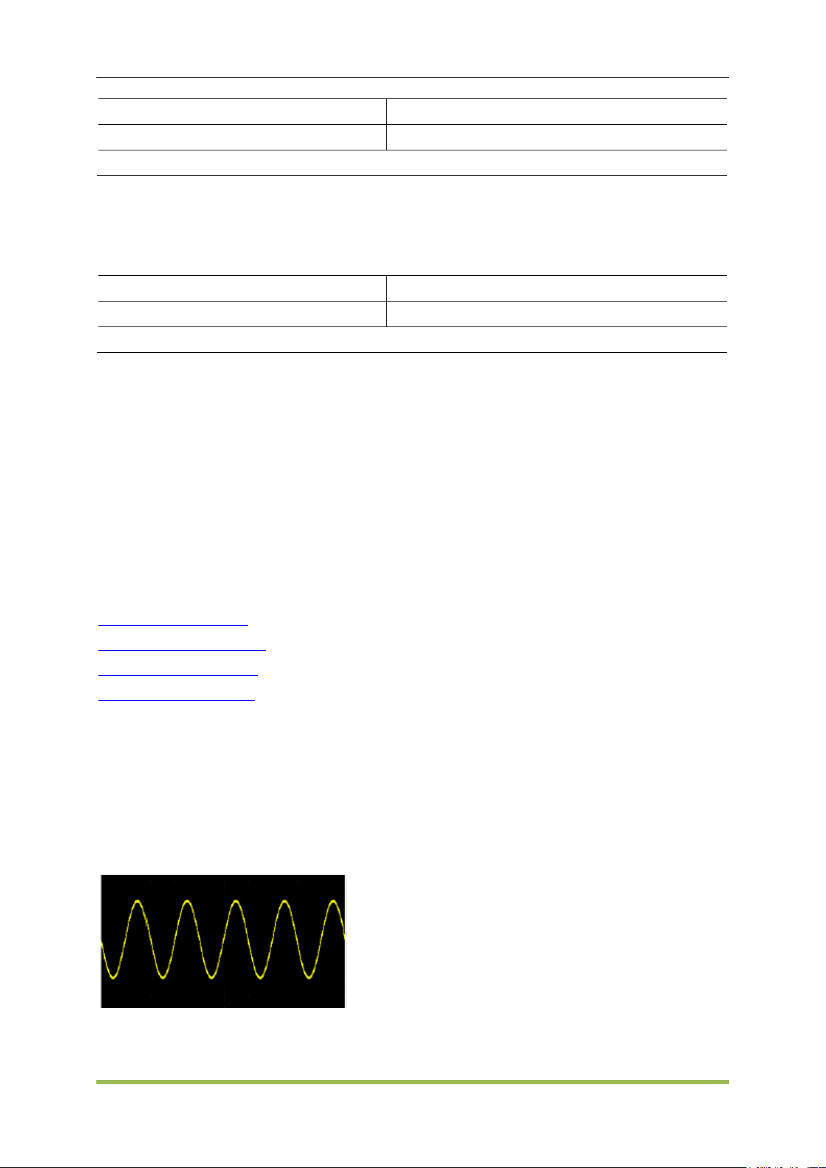
SCPI Programming Reference
Parameter
Typical Return
2 mVpp to 20 Vpp, default 200mVpp
+10.0000000000000E+00
Set output amplitude on CH1 to 10Vpp: SOURce1:VOLTage 10
Parameter
Typical Return
-10 to +10V, default 0V
+1.0000000000000E-01
Set offset voltage to on CH1 100 mV: SOURce1:VOLTage:OFFSet 0.1
SOURce<n>:VOLTage:OFFSet <offset>|MINimum|MAXimum
SOURce<n>:VOLTage:OFFSet? [MINimum|MAXimum]
Sets DC offset voltage.
The relationship between offset voltage and output amplitude is shown below.
|Voffset| < Vmax - Vpp/2
Setting the high and low levels also sets the waveform amplitude and offset. For example, if you
set the high level to +2 V and the low level to -3 V, the resulting amplitude is 5 Vpp, with a
-500 mV offset.
5.3 Programming Examples
These programming examples help you get started with common tasks.
Configure a Sine Wave
Configure a Square Wave
Configure a Ramp Wave
Configure a Pulse Wave
5.3.1 Configure a Sine Wave
This section describes the configuration of a sine wave function.
Description
A sine wave has amplitude, offset, and phase relative to sync pulse.
The following commands produce the sine wave shown above.
SOURce1:FUNCtion SINusoid
SOURce1:FREQuency 100000
HDG2000 Series Arbitrary Waveform Generator 93
Page 95

SCPI Programming Reference
SOURce1:VOLTage 2
OUTPut1 ON
SOURce1:PHASe 90
5.3.2 Configure a Square Wave
Description
A square wave has amplitude, offset, and phase relative to sync pulse. It also has duty cycle and
period. Its amplitude and offset can also be set using high and low voltage values.
The following commands produce the square wave shown above.
SOURce1:FUNCtion SQUare
SOURce1:FUNCtion:SQUare:DCYCle 20
SOURce1:FREQuency 100000
SOURce1:VOLTage 4
OUTPut1 ON
5.3.3 Configure a Ramp Wave
Description
A ramp wave has amplitude, offset, and phase relative to sync pulse. It also has symmetry for
creating triangular and other similar waveforms.
The following commands produce the ramp wave shown above.
SOURce1:FUNCtion RAMP
SOURce1:FUNCtion:RAMP:SYMMetry 25
SOURce1:FREQuency 1000
SOURce1:VOLTage 2
HDG2000 Series Arbitrary Waveform Generator 94
Page 96

SCPI Programming Reference
SOURce1:VOLTage:OFFSet 1.0
OUTPut1 ON
5.3.4 Configure a Pulse Wave
Description
A pulse wave has amplitude, offset, and phase relative to sync pulse. It also adds edge slope,
period, and duty cycle (orpulse width). Its amplitude and offset can also be set using high and low
voltage values.
The following commands produce the pulse wave shown above.
SOURce1:FUNCtion PULS
SOURce1:FUNCtion:PULSe:TRANsition:LEADing 0.00000004
SOURce1:FUNCtion:PULSe:TRANsition:TRAiling 0.000001
SOURce1:FUNCtion:PULSe:WIDTh 0.000003
SOURce1:FREQuency 200000
SOURce1:VOLTage 3
OUTPut1 ON
HDG2000 Series Arbitrary Waveform Generator 95
Page 97

Appendix A
HDG2000 Series Command Quick Reference
DATA Commands
SOURce<n>:DATA:DAC16 <addr>,<dots_num>,<binary_block>| <value>,<value>, . . .
SOURce<n>:DATA: <addr>,<dots_num>,<binary_block>| <value>,<value>, . . .
Output Configuration Commands
SOURce<n>:FUNCtion <wave>,
SOURce<n>:FUNCtion?
FREQUENCY CONTROL
Appendix
SOURce<n>:FREQuency<frequency>|MINimum|MAXimum
SOURce<n>:FREQuency? [MINimum|MAXimum]
SOURce<n>:FREQuency:STARt<frequency>|MINimum|MAXimum
SOURce<n>:FREQuency:STARt? [MINimum|MAXimum]
SOURce<n>:FREQuency:STOP <frequency>|MINimum|MAXimum
SOURce<n>:FREQuency:STOP? [MINimum|MAXimum]
SOURce<n>:FREQuency:CENTer <frequency>|MINimum|MAXimum
SOURce<n>:FREQuency:CENTer? [MINimum|MAXimum]
SOURce<n>:FREQuency:SPAN <frequency>|MINimum|MAXimum
SOURce<n>:FREQuency:SPAN? [MINimum|MAXimum]
VOLTAGE
SOURce<n>:VOLTage <amplitude>|MINimum|MAXimum
SOURce<n>:VOLTage? [{MINimum|MAXimum}]
SOURce<n>:VOLTage:OFFSet <offset>|MINimum|MAXimum
SOURce<n>:VOLTage:OFFSet? [MINimum|MAXimum]
SQUARE WAVE
SOURce<n>:FUNCtion:SQUare:DCYCle <percent>|MINimum|MAXimum,
SOURce<n>:FUNCtion:SQUare:DCYCle? [MINimum|MAXimum]
RAMP
SOURce<n>:FUNCtion:RAMP:SYMMetry <symmetry>|MINimum|MAXimum,
SOURce<n>:FUNCtion:RAMP:SYMMetry? [MINimum|MAXimum]
HDG2000 Series Arbitrary Waveform Generator 96
Page 98

PLUSE
SOURce<n>:FUNCtion:PULSe:DCYCle <percent>|MINimum|MAXimum
SOURce<n>:PULSe:DCYCle? [MINimum|MAXimum]
SOURce<n>:FUNCtion:PULSe:WIDTh <seconds>|MINimum|MAXimum
SOURce<n>:FUNCtion:PULSe:WIDTh? [MINimum|MAXimum]
SOURce<n>:FUNCtion:PULSe:TRANsition:LEADing<seconds>|MINimum|MAXimum
SOURce<n>:PULSe:TRANsition:LEADing? [MINimum|MAXimum]
SOURce<n>:FUNCtion:PULSe:TRANsition:TRAiling <seconds>|MINimum|MAXimum
SOURce<n>:PULSe:TRANsition:TRAiling? [MINimum|MAXimum]
ARBITRARY WAVEFORM
SOURce<n>:FUNCtion:ARBitrary <filename>, SOURce<n>:FUNCtion:ARBitrary?
SOURce<1|2>:FUNCtion:ARBitrary:PTPeak <voltage>|MINimum|MAXimum,
SOURce<1|2>:FUNCtion:ARBitrary:PTPeak?{MINimum|MAXimum}
SOURce<1|2>:FUNCtion:ARBitrary:SRATe {<sample_rate>|MINimum|MAXimum},
Appendix
SOURce<1|2>:FUNCtion:ARBitrary:SRATe? {MINimum|MAXimum}
OUTPUT
OUTPut<n> ON|OFF,
OUTPut<n>?
OUTPut:SYNC:SOURce CH1|CH2
Modulation Commands
SOURce<n>:MOD ON|OFF
SOURce<n>:MOD?
SOURce<n>:MOD:TYPe AM|FM|PM|ASK|FSK|PSK|PWM|BPSK
SOURce<n>:MOD:TYPe?
AM
SOURce<n>:MOD:AM:DEPTh <depth>|MINimum|MAXimum
SOURce<n>:MOD:AM:DEPTh? [MINimum|MAXimum]
SOURce<n>:MOD:AM:SOURce INTernal|EXTernal
SOURce<n>:MOD:AM:SOURce?
SOURce<n>:MOD:AM:INTernal:FREQuency <frequency>|MINimum|MAXimum
SOURce<n>:MOD:AM:INTernal:FREQuency? [MINimum|MAXimum]
SOURce<n>:MOD:AM:INTernal:FUNCtion SINusoid|SQUare|RAMP
SOURce<n>:MOD:AM:INTernal:FUNCtion?
HDG2000 Series Arbitrary Waveform Generator 97
Page 99

FM
SOURce<n>:MOD:FM:DEViation <deviation>|MINimum|MAXimum
SOURce<n>:MOD:FM:DEViation? [MINimum|MAXimum]
SOURce<n>:MOD:FM:SOURce INTernal|EXTernal
SOURce<n>:MOD:FM:SOURce?
SOURce<n>:MOD:FM:INTernal:FREQuency <frequency>|MINimum|MAXimum
SOURce<n>:MOD:FM:INTernal:FREQuency? [MINimum|MAXimum]
SOURce<n>:MOD:FM:INTernal:FUNCtion SINusoid|SQUare|RAMP
SOURce<n>:MOD:FM:INTernal:FUNCtion?
PM
SOURce<n>:MOD:PM:DEViation <deviation>|MINimum|MAXimum
SOURce<n>:MOD:PM:DEViation? [MINimum|MAXimum]
SOURce<n>:MOD:PM:SOURce INTernal|EXTernal
SOURce<n>:MOD:PM:SOURce?
Appendix
SOURce<n>:MOD:PM:INTernal:FREQuency <frequency>|MINimum|MAXimum
SOURce<n>:MOD:PM:INTernal:FREQuency? [MINimum|MAXimum]
SOURce<n>:MOD:PM:INTernal:FUNCtion SINusoid|SQUare|RAMP
SOURce<n>:MOD:PM:INTernal:FUNCtion?
ASK
SOURce<n>:MOD:ASKey:AMPLitude <amplitude>|MINimum|MAXimum
SOURce<n>:MOD:ASKey:AMPLitude? [MINimum|MAXimum]
SOURce<n>:MOD:ASKey:INTernal:RATE <frequency>|MINimum|MAXimum
SOURce<n>:MOD:ASKey:INTernal:RATE? [MINimum|MAXimum]
SOURce<n>:MOD:ASKey:SOURce INTernal|EXTernal
SOURce<n>:MOD:ASKey:SOURce?
SOURce<n>:MOD:ASKey:POLarity POSitive|NEGative
SOURce<n>:MOD:ASKey:POLarity?
FSK
SOURce<n>:MOD:FSKey:FREQuency <frequency>|MINimum|MAXimum
SOURce<n>:MOD:FSKey:FREQuency? [MINimum|MAXimum]
SOURce<n>:MOD:FSKey:INTernal:RATE <frequency>|MINimum|MAXimum
SOURce<n>:MOD:FSKey:INTernal:RATE? [MINimum|MAXimum]
SOURce<n>:MOD:FSKey:SOURce INTernal|EXTernal
SOURce<n>:MOD:FSKey:SOURce?
SOURce<n>:MOD:FSKey:POLarity POSitive|NEGative
SOURce<n>:MOD:FSKey:POLarity?
HDG2000 Series Arbitrary Waveform Generator 98
Page 100

PSK
SOURce<n>:MOD:PSKey:PHASe <phase>|MINimum|MAXimum
SOURce<n>:MOD:PSKey:PHASe ? [MINimum|MAXimum]
SOURce<n>:MOD:PSKey:INTernal:RATE <frequency>|MINimum|MAXimum
SOURce<n>:MOD:PSKey:INTernal:RATE? [MINimum|MAXimum]
SOURce<n>:MOD:PSKey:SOURce INTernal|EXTernal
SOURce<n>:MOD:PSKey:SOURce?
SOURce<n>:MOD:PSKey:POLarity POSitive|NEGative
SOURce<n>:MOD:PSKey:POLarity?
BPSK
SOURce<n>:MOD:BPSKey:PHASe <phase>|MINimum|MAXimum
SOURce<n>:MOD:BPSKey:PHASe ? [MINimum|MAXimum]
SOURce<n>:MOD:BPSKey:INTernal:RATE <frequency>|MINimum|MAXimum
SOURce<n>:MOD:BPSKey:INTernal:RATE? [MINimum|MAXimum]
Appendix
PWM
SOURce<n>:MOD:PWM:DEViation <deviation>|MINimum|MAXimum
SOURce<n>:MOD:PWM:DEViation? [MINimum|MAXimum]
SOURce<n>:MOD:PWM:SOURce INTernal|EXTernal
SOURce<n>:MOD:PWM:SOURce?
SOURce<n>:MOD:PWM:INTernal:FREQuency <frequency>|MINimum|MAXimum
SOURce<n>:MOD:PWM:INTernal:FREQuency? [MINimum|MAXimum]
SOURce<n>:MOD:PWM:INTernal:FUNCtion SINusoid|SQUare|RAMP
SOURce<n>:MOD:PWM:INTernal:FUNCtion?
Frequency Sweep
SOURce<n>:SWEep ON|OFF
SOURce<n>:SWEep?
SOURce<n>:SWEep:TIME <seconds>|MINimum|MAXimum
SOURce<n>:SWEep:TIME? [MINimum|MAXimum]
SOURce<n>:SWEep:HTIMe <seconds>|MINimum|MAXimum
SOURce<n>:SWEep:HTIMe? [MINimum|MAXimum]
SOURce<n>:SWEep:RTIMe <seconds>|MINimum|MAXimum
SOURce<n>:SWEep:RTIMe ? [MINimum|MAXimum]
SOURce<n>:SWEep:TRIGger:SOURce INTernal|EXTernal
SOURce<n>:SWEep:TRIGger:SOURce?
SOURce<n>:SWEep:TRIGger:SLOPe POSitive|NEGative
SOURce<n>:SWEep:TRIGger:SLOPe?
HDG2000 Series Arbitrary Waveform Generator 99
 Loading...