

Hans Pausch ET 2000 User manual
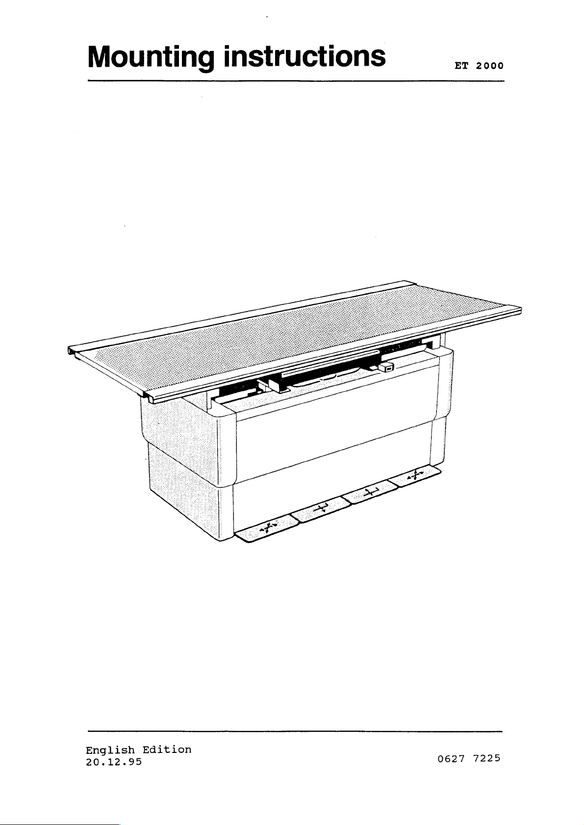
Mounting
instructions
2
2000
English
20.12.95
Edition
0627
7225
CONTENTS
PAGE
1.
1.1
1.2
1.3
1.4
1.5
1.6
1.6.1
1.7
1.8
1.9
1.10
1.11
1.12
1.13
1.14
2.
2.1
2.2
2.3
2.4
2.4.1
2.4.2
2.4.3
2.4.4
2.4.5
2.4.6
2.4.7
2.4.8
2.5
2.6
2.6.1
2.7
Technical
General
Weight
Measures
Measures
Component
Dimensional
Dimensional
Mains
Special
Measuring
Data
Safety
of
Components
of
and
Designations
Connection
Tools
Instruments
Transformer
Circuit
Wiring
Component
Component
Installation
Preparing
Uncrating
Table
Bucky
Philips
Bucky
Yamato
Picker
Diagram
Diagram
designation
Designations
the
and
Installation
Installation
P
EP
Shimadzu
Villa
Liebel-Flarsheim
Siemens
Mains
Mounting
Mounting
Fastening
Connection
of
of
of
Procedures
Components
Weights
Drawings
Drawings
Data
Required
Diagram
230
Floor
Preparing
Table
Table
Top
Top
Covers
inc.
Floor
Packing
Required
115/208/230
V
for
electrical
for
the
and
Leveling
in
Small
Diagram
Table
Rooms
Material
V
diag
3
3
3
3
4
5
6
7
7
7
8
9
10
11
12
13
13
14
16
18
18
18
19
19
19
19
19
19
20
21
21
3.
3.1
3.2
4.
4.1
4.2
4.3
4.3.4
4.4
0627
Adjustments
Exposure
Control
Technical
Mechanical
Functional
Spare
Spare
Inspection
7225
Height
Electronics
Maintenance
and
Tests
Parts
Part
List
Certification
・
Adjustments
Electrical
-2-
Tests
21
21
23
28
29
32
36
07/95
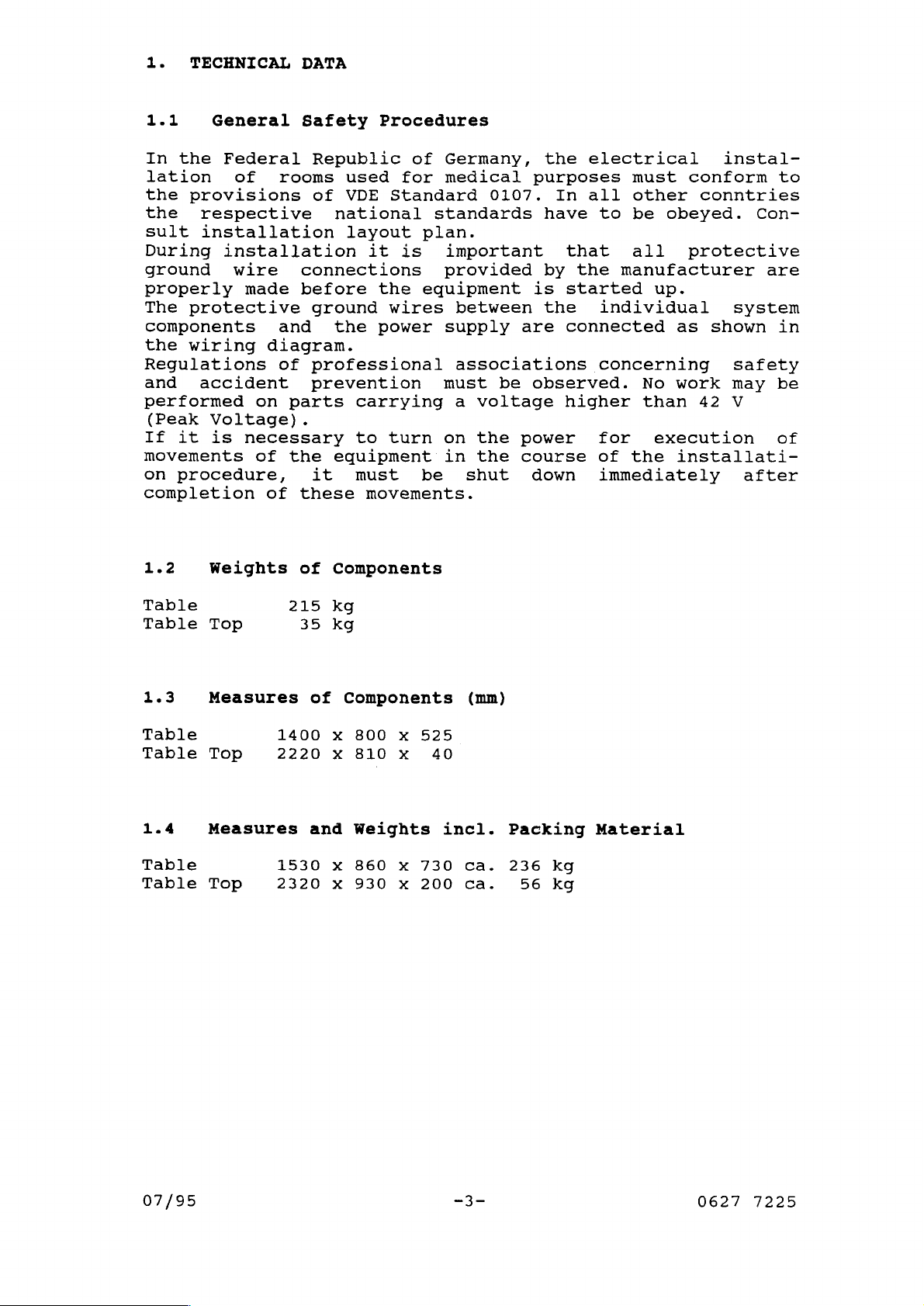
1.
TECHNICAL
DATA
1.1
In
lation
the
the
sult
During
ground
General
the
Federal
provisions
respective
installation
installation
properly
The
protective
components
the
wiring
Regulations
and
performed
(Peak
If
movements
on
accident
Voltage).
it
is
procedure,
completion
1.2
Weights
of
rooms
wire
made
and the
diagram.
of
on
parts
necessary
of
the
of
Safety
Republic
of
Procedures
used
VDE
national
layout
it is
connections
before
the
ground
power
professional
prevention
carrying
to
equipment
it
must
these
of
movements.
Components
of
for
Standard
standards
plan.
provided
equipment
wires
must
turn
on
in
be
Germany,
medical
purposes
0107.
important
between
supply
are
associations
be
observed.
a
voltage
the
power
the
course
shut
down
the
In
have
that
by
is
started
the
connected
higher
electrical
must
all
other
to be
all
the
manufacturer
individual
concerning
No
than
for
of
the
immediately
instal-
conform
conntries
obeyed.
protective
up.
as
shown
work
42
execution
installati-
Con-
are
system
safety
may
V
after
to
in
be
of
Table
Table
1.3
Table
Table
1.4
Table
Table
Top
Measures
Top
Measures
Top
215
35
1400
2220
1530
2320
kg
kg
of
Components
x
x
and
x
x
800
x
810
x
Weights
860
x
930
x
525
40
730
200
(mm)
incl.
ca.
ca.
Packing
236
kg
56
kg
Material
07/95
-3-
0627
7225

1.5
Component
Designations
Table
Profile
wD
Table
0
Bucky
0
Telescopic
Table
mods
Switch
Safety
Top
Rails
Frame
Unit
Section
Base
Pedals
Interlock
of
Switch
Table
0627
7225
-4-
07/95
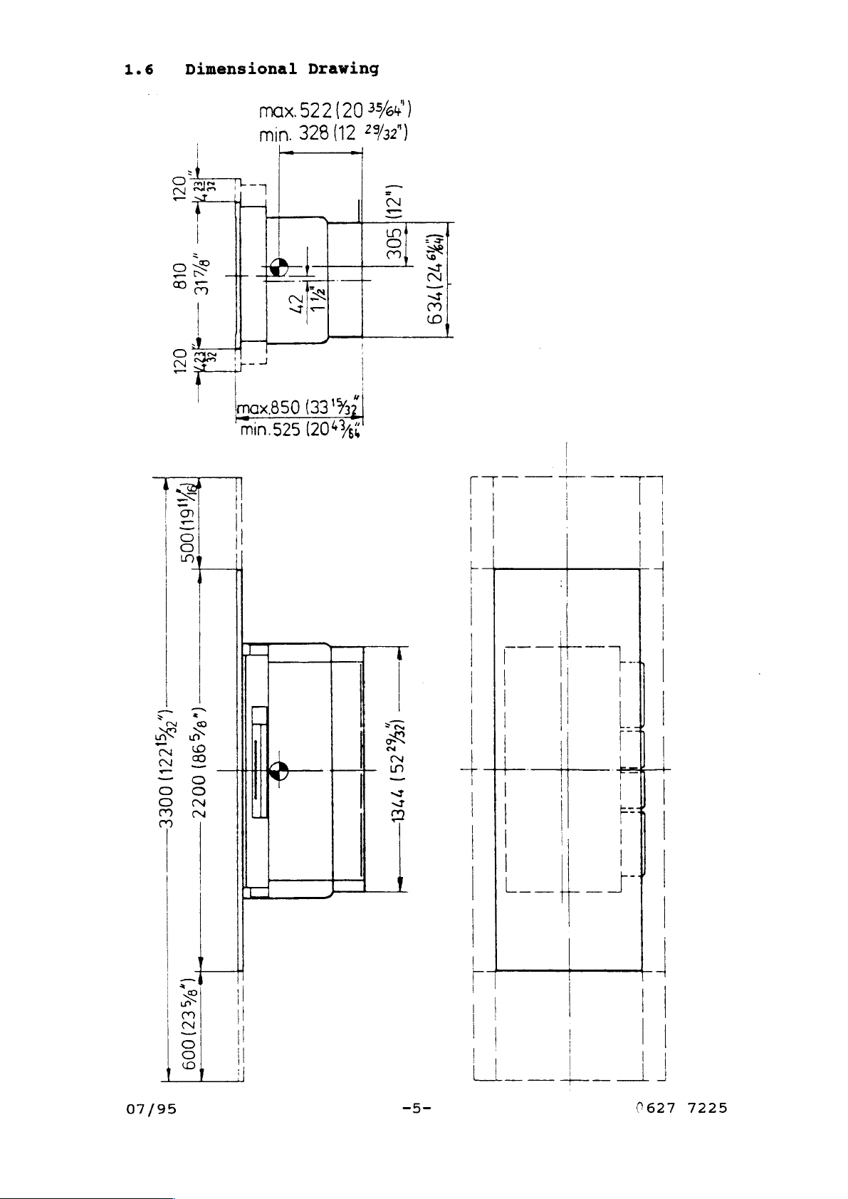
1.6
Dimensional
k
οζι
i
一
MAE
018
L
と
Е
г
H
8
と
à
7
Drawing
SS
SA
8
區
!
3a
та
(20/50€
(Yo
721789
=В
OZ!
21611008
|
Ey
E
(TTL
TT
=
(9/98)
(„ЕСИ
8
7
co
SIE
X
|
UM
LEE)
olp
WIN
SIN
olo
ーー
me
ot
ーー
=
ss
=
(264,75)
O
—+-
|
0058
07/95
0022
>
,%
€2)
009
=
TL
TTT
ори
|
77€
LL
_
JJ
0627
7225
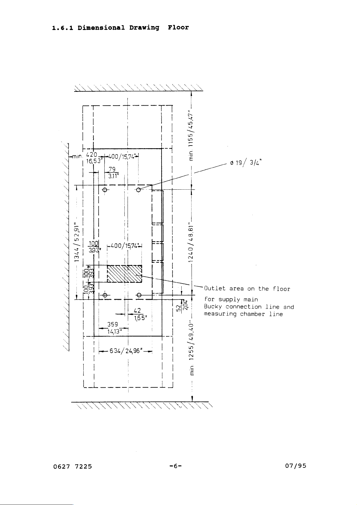
1.6.1
Dimensional
Drawing
Floor
a
snr
S
du
>
:
N
、
` X x
SN
o
|
|
|
|
|
ト
20740015742!
Г
|
[|
|
|
|
|
||
Ίο
和
a
二
al
2
|
一
al
a
|
14
|
93
00
a
|
|
|
|
へ x 、
M
|
|
~
es
|
!
|
311
O
|
|
|
|
|
|
2400/1824
|
|
A.
ИА
Y
в
|
二
一
一
τος
|
-一
12
、
NC
x x 、
|
|
|
|
--
|
|
|
十
二
|,
|
|
|
ll
|
[和
|
上
|
DI
dios
41
一
|
」
|
|
で
se
=
|
|
2;
ミ
3
|
X
|
8
a
=
E
|
|
|
=
로
5
3
7
“—Qutlet
|
for
supply
Bucky
measuring
connection
$
19/
area
3/4"
/
on
the
main
chamber
floor
line
line
and
| | 3599
>
V
>
-L
||
||
Е
0627
7225
|
1413"!
| |
| + 634/24,96"—
|
|
|
АО
|
στ
|
à
|
i
|
|
고
|
th
| |
|
|
|
2
<
と
|
|
1
-6-
07/95
1.7
Mains
Connection
Data
Mains
Power
Frequency
Connection
Supply
Nominal
Mains
1.8
Torque
Masonry
1.9
Machinist’s
Connection
Special
Wrench
Measuring
Measuring
Voltmeter
Voltage
:
Current
Drill,
Water
Tape
Cable
(Fuse)
Capacity
Tools
50
12
Required
Nm
mm
Instruments
Level
:
:
:
(5
mkp)
diameter
3 x 2.5
230
50/60
V
(117/208
Hz
mm2
5 A (slow-blow)
:
0.75
kVA
Required
(1L/N/PE)
V)
(10/6,25
A)
07/95
-7-
627
7225

1.10
Transformer
Diagram
115/208/230
V
I)
EJ-
一
uanpiamina
ünlem.
pao
OH
3
San
nara
(DVZA
ZH
Jv
LN
A0
で >
JV
09/08
*A80Z/SLL
4
C
им
=
ANT+
20
Va
30
9
~
>
AM
LL-
td”
EX-
0627
7225
vor
—C
+1
(ASIL)
O
110
|
FC
Ante
30
A
ею
€4-
A
r
30
1
|
(LIV
UL
OL
マン
эс
A0
jv
20.12.95
“0
LS
AQ
ο
^
JV
ZHO9/0S
'AOEZ
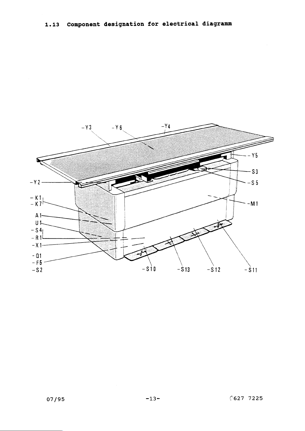
1.13
Component
designation
for
electrical
diagramm
-82
\
-S10
-813
-S12
-81
07/95
-13- (627
7225

1.14
Part
Description
for
Circuit
Diagram
No.
=AF+A1
+U1
-F1
ー ド 2
-F3
-F4
-F5
-F6
-F7
-Ki
-K2
~K4
~K5
-K6
-K7
Description
Control
Frequency
Fuse
Fuse
Fuse
Fuse
Fuse
Fuse
Fuse
Motor
Relay motor
Relay
Relay
Relay
Relay
Service
Heigth
Board
transformer
24
V
20
V
130
mains
+12
-12
conductor
n>0
safety switch
indermediate
exposure
switch
potentiometer
Converter
AC,
V
input
V
DC
V
DC
conductor
primary
20
V
height
AC
-82
-53
-S4
ーS5
-S10
-S11
-S12
-S13
-T1
-T2
-X1
-X2
-X3
-X4
-Х4а
-X4b
-X5
-X7
-X8
-X9
-X10
-X11
-X12
-X13
-X14
-X15
~X16
Service
Switch
Safety
Safety
Pedal
Pedal
Pedal
Pedal
Mainstransformer
Transformer
Terminal
Plug
Plug
Plug
Plug
Plug
Plug
Plug
Plug
Plug
Plug
Plug
Plug
Plug
Plug
Plug
Test
push
for
limit
push
for
for
for
for
strip
in
connection
in
connection
in
connection
in
connection
in
connection
in
connection
in
connection
in
connection
in
connection
in
connection
in
connection
in
connection
connection
in
connection
in
in
connection
socket
brake
of
switch
bottom
table
Table
top
top
verticalal
vertcal
for
electronics
Bucky
brake
brake
upwards
downwards
to
motor
to
transformer
to
motordrive
to
anti
anti
to
to
pedal
to
left
to
right
on
Bucky
mains
to
height
to
control
to
U1
to
U1
for
Combi-Elevator
carriage
collision
collision
strip
transverse
transverse
carriage
input
measuring
control
motor
drive
drive
brake
brake
unit
signal
signal
voltage
0627
7225
-14-
07/95
 Loading...