

OPERATING INSTRUCTIONS CS 2000 TOMO
_____________________________________________________________________________________________________________
0125
__________________________________________________________________________________________________
English Edition
07/98 -1 of 24- 0125 7322
Rev. 02 © 1998 Hans Pausch Röntgengerätebau Graf-Zeppelin-Str. 1 D-91056 Erlangen ALL RIGHTS RESERVED Ru

CONTENTS Page
Technical Safety Procedures
- Regulations 3
Product Safety
- Electrical safety 4
- Mechanical safety 4
- Rest risk 4
- Danger of Injury 4
- X-Ray Protection. 5
- Explosion protection 6
- Interference suppression 6
- Classification of product 6
- EC Conformity 6
- Environment condition 6
- Disposal of equipment 6
Design Features
- Conception 7
General
- Brief Description 8
- Range of Application 9
Installation
- Floor Space Required 10
- Room Height 10
- Power 10
- Mains 10
- AL weakening equivalent 10
Operating Elements
- Arrangement 11
- Meaning of Symbols/Function 12
- Procedures before exposure 16
- Accessories 19
Maintenance
- Important note 21
- Operator’s service and maintenance 21
- Periodic maintenance 21
- Cleaning 21
- Disinfection 22
- The Council Directive 93/42EEC on Medical Devices 22
Location of Name Plate
- Labeling 23
0125 7322 - 2 of 24- 07/98
Rev. 02 © 1998 Hans Pausch Röntgengerätebau Graf-Zeppelin-Str. 1 D-91056 Erlangen ALL RIGHTS RESERVED Ru

Important Note:
To ensure proper operation of this product it is essential that the service personnel is familiar with the "Operating Instructions" which should be studied carefully
before use.
Special attention is to be given to the chapter "Safety Notes"
The equipment must be used in accordance with the safety procedures described below, and must not be used for purposes other than those for which it
was designed. The equipment may only be used by persons having recognized
qualification, including adequate training in radiation protection, authorizing them to
perform the examination or treatment carried out.
It is the responsibility of the user to ensure that the government regulations are
observed in the installation and operation of the equipment.
Technical safety note:
Regulations
If legal regulations govern the operation of the above equipment, it is the responsibility of the operator to observe them.
For the safety of patients, operators and others, as well the efficient functioning
of the equipment it is necessary to have periodic service inspections at 12-month
intervals according to the maintenance schedule. Please apply to your service organization for inspection and maintenance.
Inspections intervals must by all means meet the requirements of the respective
legislation or government regulations.
Changes and additions to the product must comply with the relevant legislation
as well as with the accepted standards of good manufacturing practice.
As manufacturer of electromedical systems, we assume responsibility for the
safety of the equipment only if maintenance, repairs and changes are carried out
exclusively by us or third parties expressly authorized by us to do so, and if defective parts relating to the safety of the equipment are replaced by genuine spare
parts.
We recommend that the service personnel is being asked to issue a certificate
specifying the kind and extend of things or work ranges. The certificate should
also show the date of repair, the name of the service company and the signature
of the technician.
Before operating the equipment, the operator must check all devices concerning
the safe and efficient functioning.
07/98 -3 of 24- 0125 7322
Rev. 02 © 1998 Hans Pausch Röntgengerätebau Graf-Zeppelin-Str. 1 D-91056 Erlangen ALL RIGHTS RESERVED Ru

Please see: Daily check in chapter Maintenance.
If the user of this equipment likes to combine the unit with other units, components or assemblies and this can not be made clear from the technical data, he
must question us as manufacturer or another expert to make sure that the safety
of the patients and operator is given by the planned combination.
Product Safety
Electrical safety
Only trained service personnel are permitted to remove covers and panels from
the x-ray equipment .
In the Federal Republic of Germany, the electrical installation of rooms used for
medical purposes must conform to the provisions of the VDE Standard 0107. In all
other countries, the provisions of the applicable local laws and regulations have
priority.
The unit is only prepared for solid installation with an all poled separation from the
power (ICE 601, Kap. 57.1).
Mechanical safety
It is the responsibility of the operator to ensure safety of patient while the unit is
in operation by visual check, proper patient positioning, and use of devices that
are provided.
Rest risk:
During proper operation and in case that a first mistake may occur there will be no
damage to patient and/or environment.
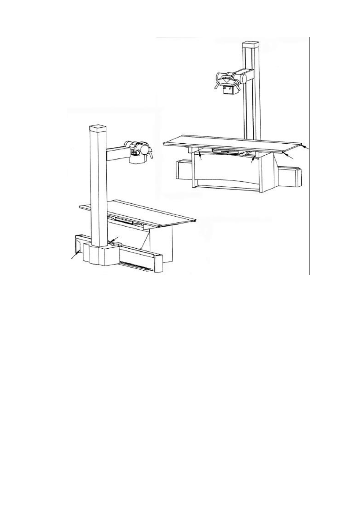
Danger of injury
The solid black arrows and dotted lines in the illustration show areas which present
potential Danger of Injury to operating personal and patient from the equipment
motion.
See next page.
0125 7322 - 4 of 24- 07/98
Rev. 02 © 1998 Hans Pausch Röntgengerätebau Graf-Zeppelin-Str. 1 D-91056 Erlangen ALL RIGHTS RESERVED Ru
X-Ray Protection.
The unit has no controls with which radiation could be triggered.
Exposure is triggered only from the radiation-protected location of the generator.
The general radiation-protection measures must be observed.
In addition, we recommend the following:
1 Set the tube current as low as possible .
2 Limit the radiation field to the maximum possible extent.
3 Keep as far away as possible.
4 Provide radiation protection for the patient.
07/98 -5 of 24- 0125 7322
Rev. 02 © 1998 Hans Pausch Röntgengerätebau Graf-Zeppelin-Str. 1 D-91056 Erlangen ALL RIGHTS RESERVED Ru
Explosion Protection
This equipment is not designed for use in areas where explosion hazard can take
place.
Only skin cleansing agents may be used which form non-explosive mixtures with
air.
Interference Suppression
The equipment complies with the EMC-requirements of the guideline 89/336 EWG.
of
* Special board International Electronic Commission (IEC) This unit complies to
EN 55011 and the reference value is according EN 55011 Group 1 Class B the in-
ternational electrotechnical committee (IEC).
Classification of product
The equipment complies to the protection degree of Class 1 and for protection
against electric shock Type B.
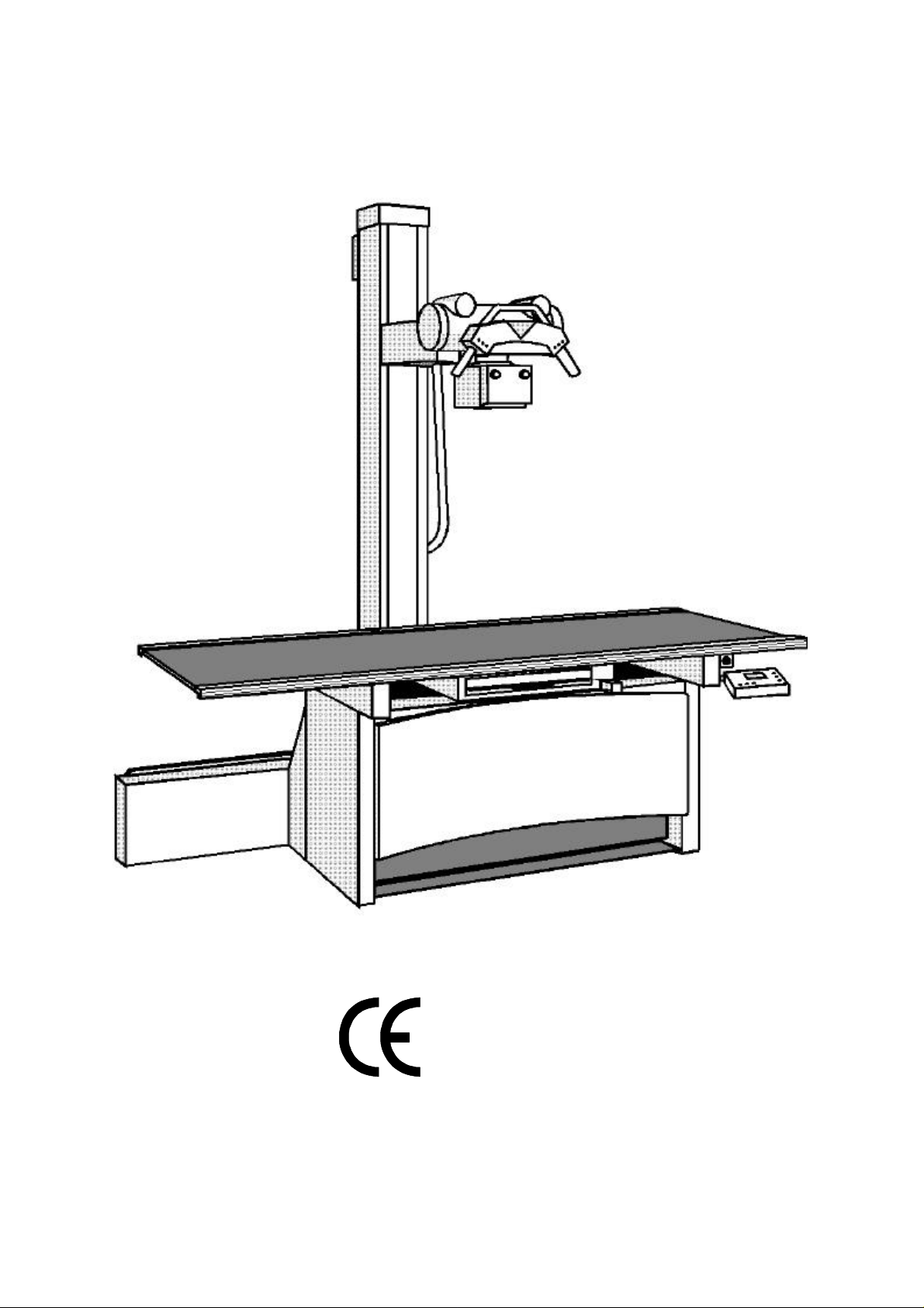
EC Conformity
The CS 2000 TOMO to which this declaration relates fulfills the essential requirements for safety of medical electrical equipment and follows the provisions of
Medical Device Directive 93/42 EEC part 11 para. 3 according the procedure in
annex II.
The CE-Mark is only applicable for the product without X-ray components and
Bucky.
The declaration of EC-conformity can be sent to you by request:
Write to:
Hans Pausch
Röntgengerätebau
c/o Quality Assurance Sys. Mgr.
Postfach 28 60
D-91016 Erlangen
Fax #: ..49 9131 99 24 22
Enviroment Condition
Surrounding temperature range 10° C to 40° C
Humidity 20% to 80%
Atmospheric pressure 700 hPa to 1100 hPa
Disposal of equipment
Legal waste disposal regulations may apply to the disposal of this product. To
avoid causing damage to the environment and personal injury, we recommend that
you contact your Customer Services representative before permanently removing
this product from service.
0125 7322 - 6 of 24- 07/98
Rev. 02 © 1998 Hans Pausch Röntgengerätebau Graf-Zeppelin-Str. 1 D-91056 Erlangen ALL RIGHTS RESERVED Ru
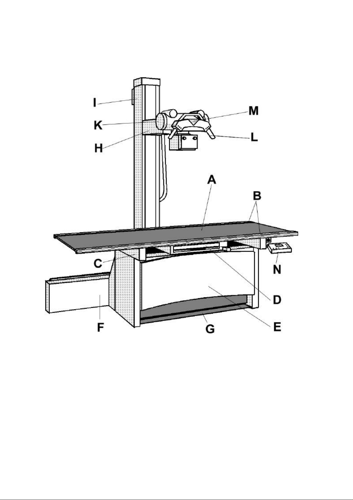
Design Features
Constructional Conception
A Table top, floating, manually movable, scratch-proof
B Profile rail with trim cover, smooth, accepts accessories
C Upper table frame
D Bucky unit, movable
E Table base, solid, vibration-free
F Guide rails for tube stand
G Foot treadle
H Vertical carriage with X-ray tube support arm
I Column, rotatable
K X-ray tube
L Control handle
M Protractor
N Control-panel for Tomo
07/98 -7 of 24- 0125 7322
Rev. 02 © 1998 Hans Pausch Röntgengerätebau Graf-Zeppelin-Str. 1 D-91056 Erlangen ALL RIGHTS RESERVED Ru

General
Short description
The equipment consists of a patient table with coordinate table top and diaphragm carriage,
and of a column with X-ray tube, collimator and control arm.
The solid, vibration-free table base and the rail stand with column form one unit.
The large and 2.20 m long, floating table top is manually movable and locks electromagnetically. The table top is provided for a maximum patient weight of 136 kg. It allows spacious lateral travel (60 cms to the left, 50 cm to the right and ± 12 cms transversely). For
fast and easy positioning of the patient.
Especially for patient comfort and easy cleaning, the table top offers a scratch-proof surface
(Resopal) and trim-covered, smooth profile rails on both sides, which can accept accessories.
The Bucky carriage accepts cassette trays from all renowned manufacturer. In longitudinal
direction, it is manually moved and electromagnetically locked. The shortest possible OFD
of 70 mm guarantees images of superior geometrical proportion. Low radiation absorption
by the table top reduces the X-ray amount. The brake of the Bucky is released by a pushbutton on the operating handle.
As accessory is a automatic mechanical coupler available for automatic connection from the
Bucky and tube stand.
The foot treadle along the table base allows the release of the electromagnetic table top
brakes.
The tube stand for the X-ray tube support arm and tube is moved on the rail stand parallel
to the longitudinal table axis.
The X-ray tube with collimator and control arm for the tube stand is supported by a lateral
arm fixed to the vertical carriage. Vertical movement and rotation of the tube around the
longitudinal axis of the lateral arm permit vertical, horizontal or oblique beam projections.
Each position is electromagnetically locked.
The X-ray tube with column stand rotates around the vertical column axis and catches mechanically at angles of 0° (basic position), ± 90° (for lateral exposures).
The standard tube support is intended for DIN 6836 flanged plate C.
The max. weight of the X-ray tube and collimator must not exceed 40 kg.
0125 7322 - 8 of 24- 07/98
Rev. 02 © 1998 Hans Pausch Röntgengerätebau Graf-Zeppelin-Str. 1 D-91056 Erlangen ALL RIGHTS RESERVED Ru

For operating there are 3 operating methods from the control panel while pushing the key
available:
Table mode - the automatic tube stand - Bucky linkage will adjust automatically the Bucky in
their travel range to the middle of the column. Exactly positioning of the tube at 0° and ±
90°.
Wall mode - while pushing the key two (adjustable while mounting) SIDs will be motorised
positioned while the tube rotates in direction of wall stand. By manual movement of the column is an automatically stop at the SID`s.
Tomo mode - while pushing the Prep-key the column and the Bucky drive into central position. After adjusting the tomography a test run or a linear blurring movement is possible.
Tomography starts from direction of wall stand.
The totally integrated, microprocessor controlled tomography allows linear blurring movement in Tomo mode.
The tomography exposure can be made with 8°, 20°, 30° and 40° tomo angles from 0-24
cm tomography layer height. There are 2 exposure times for each tomo angle available.
These tomo times can be programmed in correspondence with the Generator while installing.
The operator will be guided through the programme from the display of the control panel.
Range of use
The equipment is an universal X-ray examination system for doctors practices as well as for
hospitals. It provides high-quality gridded exposures and linear blurring movement on lying
patients. Large travel of the table top and uncomplicated functioning facilitate operation and
increase patient comfort. A special cassette holder is available for lateral exposures. With a
Bucky wall stand or a cassette stand, exposures can also be made with patients standing or
sitting. Without requiring wall and ceiling fixtures, the equipment easily adjust to change in
location.
Prerequisition
For safe and efficient operation of this product the personnel must be familiar with the operating instructions. The chapter on „Safety procedures“ deserves special attention.
07/98 -9 of 24- 0125 7322
Rev. 02 © 1998 Hans Pausch Röntgengerätebau Graf-Zeppelin-Str. 1 D-91056 Erlangen ALL RIGHTS RESERVED Ru

Installation Requirements
Floor space
The system is designed for stationary operation. The approximate floor space required
measures 330 cm x 152 cm. An additional 20 cm minimum distance must be kept between
tube stand and wall.
Height of room
The tube stand height is 234 cm. Installation requires a minimum room height of 245 cm.
The table top of the equipment has a working height of 75 cm above floor.
Power
The system is equipped for single-phase alternating current with fixed installation. Two versions are available, depending on order. The unit is only prepared for solid installation with
an all poled separation from the power (ICE 601, Kap. 57.1).
Without transformer, the system corresponds to nominal ratings as follows:
Nominal voltage: 115/230 V AC
Nominal current: 3/3 A
Rated frequency: 50/60 Hz
Nominal capacity: 690 VA
Mains
The mains connection requires a 30 mA circuit breaker to be installed by the customer. The
electrical installation must meet the relevant legislation, e.g. VDE 0107, IEC/SC 62A.
AL-equivalent
The weakening equivalent of the table top (patient pos. table top) is £ 0,7 mm.
According to:
DIN EN 60601-1-3 with 100 kV and HWS 3,7 mm AL
and FDA 21 CFR § 1020.30 (n) with 100 kV and HWS 2,7 mm AL.
0125 7322 - 10 of 24- 07/98
Rev. 02 © 1998 Hans Pausch Röntgengerätebau Graf-Zeppelin-Str. 1 D-91056 Erlangen ALL RIGHTS RESERVED Ru

Arrangement
1 Green LED lights when the Bucky is contered to the column
2 Green LED lights when the x-ray tube assembly rotation is catched
3 Green LED lights when the preferd SID is reached.
4 Switch for horizontal movement of the column
5 Switch for vertical movement of the x-ray tube ass.
6 Switch for tube rotation
7 Switch for release of all column brakes
8 Control handle with handgrips
9 Protractor
10 Rotation of tube stand by abrupt movement in appropriate
direction on control handle
11 Push button for Bucky
12 Hand grip for cassette tray
13 Foot treadle for table top break
16 Emergency stop switch
17 Switch for table mode
18 Switch for wall mode
19 Switch for small SID in wall mode
20 Switch for large SID in wall mode
21 Switch for tomo mode
22 Prep-switch for driving in central position
23 Switch for test run
24 Switch for selection of exposure angles
25 Switch for reducing the tomo height
26 Switch for increasing the tomo depth
27 Switch for selection of exposure time
28 Control panel display
07/98 -11 of 24- 0125 7322
Rev. 02 © 1998 Hans Pausch Röntgengerätebau Graf-Zeppelin-Str. 1 D-91056 Erlangen ALL RIGHTS RESERVED Ru

Meaning of Symbols/Function
Foot Treadle 13
unlocks the brakes for the floating table top. By fully
pressing down and staying on the foot treadle, the
table top can be moved manually in longitudinal and
in transverse directions. Release of the foot treadle
locks the table top in its changed working position.
Push button 6
unlocks the tube rotation brake. Release of the
switch locks the tube in position.
Push button 4
unlocks the tube stand brake for horizontal movement. Release of the switch locks the tube in position.
Push button 5
unlocks the tube stand brake for vertical movement.
Release of the switch locks the tube in position.
Push button 7
unlocks all column brakes. Release of the switch
locks all movements in position.
0125 7322 - 12 of 24- 07/98
Rev. 02 © 1998 Hans Pausch Röntgengerätebau Graf-Zeppelin-Str. 1 D-91056 Erlangen ALL RIGHTS RESERVED Ru
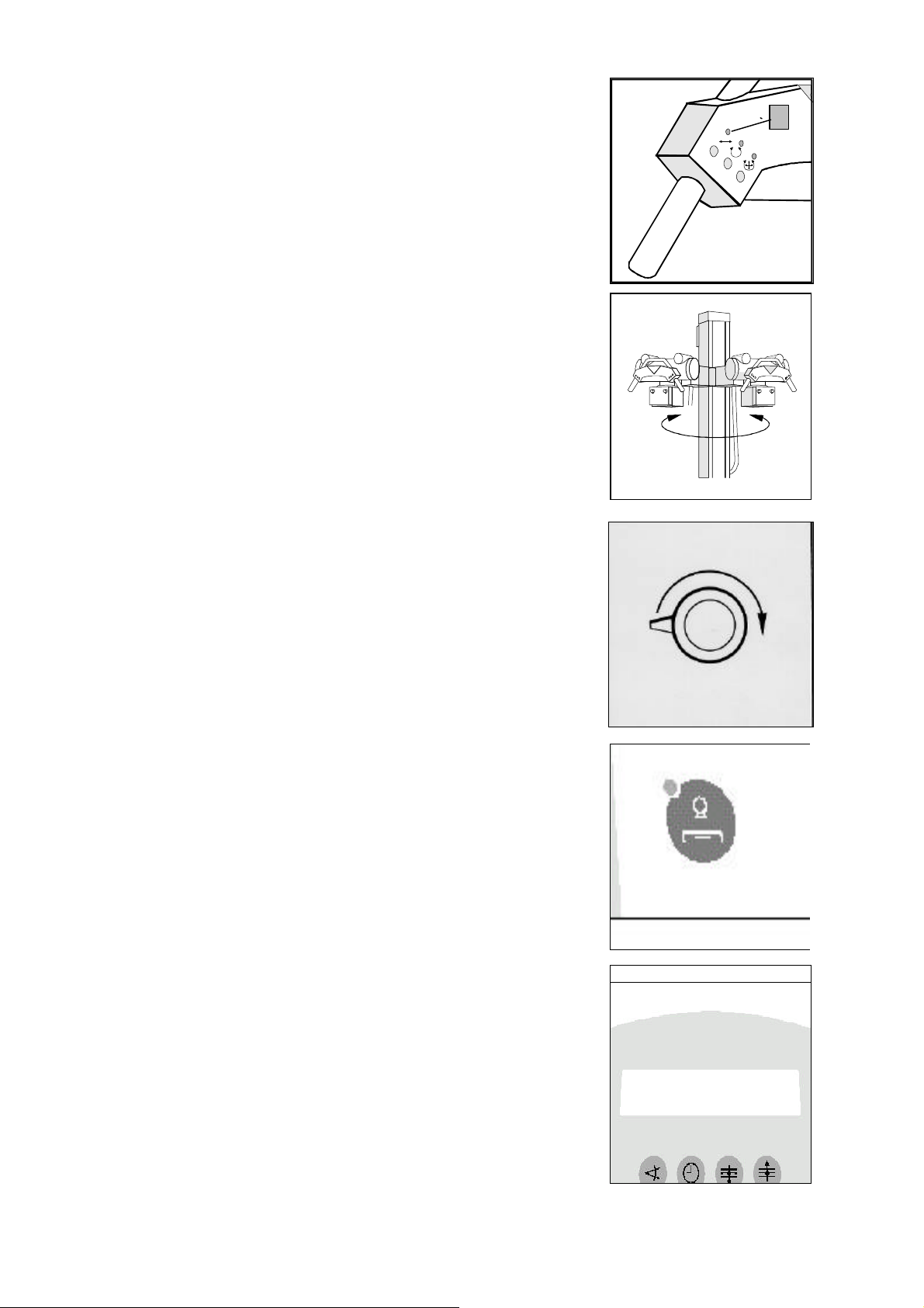
Indicator lamp green 1
1
lights up to indicate that the tube stand with tube is
coupled in the traveling area of the Bucky. The control
lamp goes out when leaving the traveling area.
(not in tomo - mode)
Turn of X-ray tube 10
The column stand with X-ray tube can be turned round
its longitudinal axle to the left or right side by 90 ° with
a strong start on both hand grips of the control arm. It
catchs at 0° , + 90° each.
Emergency Stop switch 16
The Emergency Stop switch has to be pressed inridi-
ately if there is any risk of injury for the patient, opera-
tor or the unit.
Resetting the stop switch by turning the button to the
right is only allowed when the risk of injury is surely
eliminated.
Table mode switch 17
for selection of table mode. As soon as the table mode
is activated, the SID lights up. While travelling the tube
stand, the Bucky in the table range and the X-ray tube
will follow and centered automatically. Both SIDs 1 and
2 light up when the centering has taken place.
Control panel display 28
The indication in the display will guide the operator
through the programme respectively shows the opera-
tor the working steps.
Errors in Tomo mode will be shown with error message
EXX.
Switch - off unit as soon as error lights - up and switch
- on again after approx. 3 minutes. If the error still lights
- up please contact your service support.
07/98 -13 of 24- 0125 7322
Rev. 02 © 1998 Hans Pausch Röntgengerätebau Graf-Zeppelin-Str. 1 D-91056 Erlangen ALL RIGHTS RESERVED Ru

Switch 18
for selection of wall mode. As soon as the wall mode is activated,
the LED lights up.
Switch 19
for motorised start of the adjusted small SID.
Attention: The motorised start is only possible when the X-ray
tube is on the vertical prefered SID and the green LED3 lights
up.
The tube stand drives on the SID and the X-ray tube rotates in
direction of wall stand as long as the switch 19 is pressed.
When the SID is reached, the LED at the switch lights up.
Switch 20
for motorised start of the adjusted large SID.
Attention: The motorised start is only possible when the X-ray
tube is on the vertical preferred SID and the green LED 3 lights
up.
The tube stand drives on the SID and the X-ray tube rotates in
direction of wall stand as long as the switch 20 is pressed.
When the SID is reached, the LED at the switch lights up.
Switch 21
for selection of tomo mode.
The LED lights up as soon as the tomo mode is activated.
Attention: The motorised movement are only possible, if the ta-
ble is at the exposure height, the preferred vertical SID is adjusted and the column is locked at the 0° position.
Prep-switch 22
for drive of column, Bucky and for rotation of the X-ray tube in
central starting position.
Attention: Only in this central position, the tomo parameters can
be selected.
The Prep-switch always has to be pressed after switching on the
unit (when it`s not at the central position) and after selection of
omo mode.
0125 7322 - 14 of 24- 07/98
Rev. 02 © 1998 Hans Pausch Röntgengerätebau Graf-Zeppelin-Str. 1 D-91056 Erlangen ALL RIGHTS RESERVED Ru

Switch 23
for performance of a test run respectively for drive in ex-
posure position after selection of tomo parameters.
Attention: The tube stand will stay in exposure starting
position for approx. 1 sec. during test run. The test run
starts and ends in central position.
Switch 24
for selection of tomo angles.
Attention: Only possible in central position.
Switch 25
for increasing the tomography layer height in mm steps.
Attention: Only possible in central position.
Switch 26
for reducing of the tomography layer height in mm steps.
Attention: Only possible in central position.
Switch 27
for selection of the tomography exposure time.
Attention: Only possible in central position.
07/98 -15 of 24- 0125 7322
Rev. 02 © 1998 Hans Pausch Röntgengerätebau Graf-Zeppelin-Str. 1 D-91056 Erlangen ALL RIGHTS RESERVED Ru

Procedures before Exposure
Positioning of Patient / Centering of Bucky, Exposure Object, and Tube
Position the patient on the table top.
Note
To prevent injury from the patient sitting down or
being positioned, move the tube stand and tube
out of the critical range before positioning the
patient.
Centering of the Bucky
Push switch 17 on control panel, the green LED
lights up.
Push switch 7 on control arm and drive the X-ray
tube to the preferred SID (green LED 3 lights up)
and the tube stand with tube to the middle of the
table. The centering respectively adjustment of
the Bucky will go automatically, when the column
will be moved the X-ray tube is in 0° position and
the column is in travel range of Bucky. The LED 1
lights up, when tube and Bucky are centered.
Centering of the object
Move the object into the central beam by adjusting the table top.
For this purpose, press the foot treadle 13 fully
down. The brakes of the floating table top are
now unlocked. Adjust the table top. Release the
foot treadle. The table top is locked in position.
Centering of the radiation field
Use the cassette size sensing for optimal localization of the radiation field of the collimator
(operating instruction of the collimator).
0125 7322 - 16 of 24- 07/98
Rev. 02 © 1998 Hans Pausch Röntgengerätebau Graf-Zeppelin-Str. 1 D-91056 Erlangen ALL RIGHTS RESERVED Ru

Exposure preparation
Insert cassette. Choose SID (FFD). Set expo-
sure dates on control desk. Control readiness
for exposure. Command patient to „hold your
breath“.
Note
Do not forget radiation protection devices for
the patient (lead rubber apron, gonad protec-
tion, etc.)
Oblique Exposure
Move column to the needed position. Adjust
Bucky while pressing push button 11 under ex posure object. Rotate X-ray tube and center
with switched-on optical pointer of the collimator
to middle of Bucky.
Exposure with Bucky Wall Stand
Move the table top in the direction away from
the wall stand. Slide the tube stand towards the
wall stand. Rotate the tube to a 90° angle
(indication of angle!), switch on the indicator
light, then center the tube and adjust the wall
stand Bucky to the patient by vertical move-
ment.
Lateral Exposure
For lateral exposures with the cassette holder
lateral (cf. page with accessories), rotate the
tube stand to a 90° angle. Then rotate the tube
to a 90° angle (indication of angle!). Proceed as
described above.
07/98 -17 of 24- 0125 7322
Rev. 02 © 1998 Hans Pausch Röntgengerätebau Graf-Zeppelin-Str. 1 D-91056 Erlangen ALL RIGHTS RESERVED Ru

Adjustment of tomography (in tomo mode)
Position patient on table.
Remark: Before positioning of patient move tube stand with Xray tube so that patient cannot be hurt while getting up or laying
down !
Drive X-ray tube to the preferred SID while pressing switch on
the control arm, the LED lights up.
Choose with switch 21 the tomo mode.
Press prep-switch 22 and keep depressed until the column,
stops in central position and the tomo parameters are shown on
the display.
Remark: Column, Bucky and tube cannot be moved manually in
tomo mode.
Choose tomo parameters (tomo angle, exposure time, and tomography layer height).
Press test switch 23 for performance of a test run.
Fade-in light field of collimator to film size and switch-on.
Adjust exposure object to the light field. Put cassette in Bucky.
Drive column in exposure start position with switch 23 or start
test run.
Exposure preparation
The exposure can only be triggered at the generator. Set exposure dates on control desk. Control readiness for exposure.
Command patient to „hold your breath“. Press the generator’s
exposure switch until the exposure is finished.
Note:
Do not forget radiation protection devices for the patient (lead
rubber apron, gonad protection, etc.)
Attention: If the exposure is interrupted or another exposure shall be made, the tube
stand has to be moved to the central position by pressing the prep-switch.
After selection of the tomo parameters the unit is ready for a new exposure.
It`s possible to drive to the start position with the first step of the generator`s
exposure switch.
Attention: The operator has to observe the patient and the motion of the unit during
test run and exposure and has to stop immediately if there is any danger.
0125 7322 - 18 of 24- 07/98
Rev. 02 © 1998 Hans Pausch Röntgengerätebau Graf-Zeppelin-Str. 1 D-91056 Erlangen ALL RIGHTS RESERVED Ru

Accessories
Compression Belt / Head Supports / Hip Clamps / Table Mattres
Compression Belt
Fastening and application:
Slide support frame B into profile rail at wall side or
into Bucky profile rail. Turn knob screw to clamp in
position.
Slide tightener A into front profile rail ( operator side ).
Turn hand screw C to clamp in working position opposite of B
Press ratchet mechanism F. Unroll belt and stretch
across patient.
Guide belt through complementary frame and once
around frame bar. Fix belt bracket D into slot of shaft
G. Turn ratchet mechanism E to tighten belt.
Untightening:
Press locking lever F
07/98 -19 of 24- 0125 7322
Rev. 02 © 1998 Hans Pausch Röntgengerätebau Graf-Zeppelin-Str. 1 D-91056 Erlangen ALL RIGHTS RESERVED Ru

Lateral cassette holder
The lateral cassette holder permits lateral exposures if the tube unit is mounted to a tube
swivelling device.
The lateral cassette holder is slipped in one of
the profile rails.
Grip screw (A): secures the holder at the table
top
Grip screw (B): locks the holder setting
Grip screw (C): fixes the lateral position of the
cassette clamps.
Head Supports
The head supports slide into profile rails of the
table or Bucky. The supports can be clamped
in any position desired. The patient’s head is
fixed to the appropriate exposure position by
cushioned plates on adjustable bars.
Hand screw A: Clamping head supports to
table top or Bucky.
Hand screw B: Clamping of head holder
Hand grips
The hand grips are slipped in the profile rails of
the table. They may be fixed at any position and
offer a reliable hold for the patient.
Grip screw (A): secures the grip in place
Important note:
The positioned patient may only hold on to the
hand grips. In no case may he put his hands
around the edge of the table top.
0125 7322 - 20 of 24- 07/98
Rev. 02 © 1998 Hans Pausch Röntgengerätebau Graf-Zeppelin-Str. 1 D-91056 Erlangen ALL RIGHTS RESERVED Ru

Maintenance:
Important note:
Like all technical equipment, this unit requires also a regular maintenance service
to increase the safety of the equipment.
Operator´s service and maintenance
The operator has to check the x-ray equipment for defects as listed below:
Daily routine checks
Before operating check all functions of the indicator lamp, the operating elements,
the brakes and movements. Please check existence and legibility of the inscription
and warning signs.
In case of functional defects or other deviations from the normal operation the
equipment has to be switched off at once and the service company has to be
informed.
The equipment can not be used before all defects have been eliminated.
Weekly checks
Check all cables and their connections for treaces of wear.
Periodic maintenance
For trouble-free operation of the CS 2000 TOMO as well as safety for patient and
user it is necessary to carry out a technical maintenance from the service company
every 12 months.
Please see „technical maintenance“ of the mounting instruction.
The steel rope of the column has to be replaced every three years.
Attention:
In case of failure from components, which can limit the safety of the equipment,
original spare parts have to be used.
We recommend that the service personnel is being asked to issue a certificate
specifying the kind and extend of work that was done. Also the certificate should
show the date of repair, the name of the service company and the signature of the
technician.
Cleaning:
The equipment must be switched off before cleaning. Plastic surface should only
be cleaned with mild soap. Do not use strong cleaners or solvents as they will
damage the finish or blur the lettering.
07/98 -21 of 24- 0125 7322
Rev. 02 © 1998 Hans Pausch Röntgengerätebau Graf-Zeppelin-Str. 1 D-91056 Erlangen ALL RIGHTS RESERVED Ru

At least once a month external parts and exposed tracks on which rollers move
should be wiped to remove foreign material that may have accumulated.
DO NOT USE A DAMP CLOTH.
Wipe the tracks with a cloth lightly soaked with light machine oil or WD-40.
To protect the finish, polish the equipment with PURE liquid paste wax. Do not use
wax containing a cleaning substance. Polish all enameled metal surfaces.
Disinfection:
The equipment has to be switched off before disinfection. Only disinfection meth-
ods can be used that correspond to the relevant regulations and rules as well as
the protection for explosion.
Spray disinfection is not recommended because it can get in the inside of the x-ray
equipment.
The Council Directive 93/42/EEC on Medical Devices Article 12
This document is revised at the moment by the council.
However the Article 12 must be followed by the company or the legal person who
put this X-ray unit into work.
The user is responsible for compliance and implementation of national deviations
in the EC.
0125 7322 - 22 of 24- 07/98
Rev. 02 © 1998 Hans Pausch Röntgengerätebau Graf-Zeppelin-Str. 1 D-91056 Erlangen ALL RIGHTS RESERVED Ru

Name Plate Location:
07/98 -23 of 24- 0125 7322
Rev. 02 © 1998 Hans Pausch Röntgengerätebau Graf-Zeppelin-Str. 1 D-91056 Erlangen ALL RIGHTS RESERVED Ru

Notes:
Specifications are subject to change without notice. TV/Ru
0125 7322 - 24 of 24- 07/98
Rev. 02 © 1998 Hans Pausch Röntgengerätebau Graf-Zeppelin-Str. 1 D-91056 Erlangen ALL RIGHTS RESERVED Ru
 Loading...