

Operating Instructions CS 2000
English Edition
09/99 - 1 of 20 - 0125 7321
Rev. 03 1999 Hans Pausch Röntgengerätebau Graf-Zeppelin-Str. 1 D-91056 Erlangen ALL RIGHTS RESERVED Ru

CONTENTS Page
Important Note 3
Safety-technical Remarks
- Regulations 3
Product Safety 4
- Electrical Safety 4
- Mechanical Safety 4
- Crush Zones 4
- Radiation Safety 5
- Explosion Protection 6
- Electromagnetic Interference, EMI 6
- Classification per IEC 601-1-1 6
- EC Conformity 6
- Environmental Conditions for Operation 6
- Disposal 6
Design Features
- Design 7
General
- Brief Description 8
- Area of Applicability 9
- Important Note 9
Setup
- Space Requirement 10
- Room Height 10
- Connection 10
- Line Power 10
- Al Equivalency Value 10
Control Elements
- Location 11
- Explanation of Symbols/Function 12
- Setting the Exposure Position/Exposure 14
- Accessories 16
Maintenance
- Important Note 18
- Testing by the Operator 18
- Testing by Customer Service 18
- Cleaning 18
- Disinfection 19
- EEC Guideline 93/42 Regarding Medical Products 19
Placement of Model Labels
- Labeling 20
0125 7321 - 2 of 20 - 09/99
Rev. 03 1999 Hans Pausch Röntgengeräte Graf-Zeppelin-Str. 1 D-91056 Erlangen ALL RIGHTS RESERVED Ru

IMPORTANT NOTE
Proper use of this product by operating personnel requires knowledge of these
OPERATING INSTRUCTIONS; these must be studied prior to starting up the equipment.
This radiographic equipment may be operated only by personnel who possess the required
specialized knowledge of radiation safety or who are familiar with radiation safety and who
have been instructed in the operation of the radiographic equipment.
The operator is always responsible for maintaining the regulations that apply for operation
of the radiographic equipment.
SAFETY-TECHNICAL REMARKS
Regulations
If there are legally specified regulations regarding the operation of radiographic equipment,
it is the responsibility of the operator to observe them.
In the interest of safety for patient, operating personnel as well as for third parties, tests
which assure the operating reliability and functionality of the product must be performed in
accordance with the Maintenance Instructions in intervals of 12 months.
We request that you contact your customer service department regarding performance of
these tests.
If tests are required in shorter intervals in order to comply with national specifications or
regulations, it is absolutely necessary to observe them.
Modifications and additions made to the product must be in accordance with legal
regulations as well as with generally accepted rules of the technology.
As the manufacturer of the radiographic equipment, we can assume responsibility for the
safety-technical features of the product only if:
any maintenance, repair and modification on it is carried out only by us or by facilities that
have been authorized by us for this purpose, and if there is a failure of parts which affect
the safety of the product, such parts are replaced with original spare parts.
When performing this work, we recommend that written confirmation regarding the nature
and extent of work be requested from the person performing the work, and if applicable,
include any changes made in nominal values or to the operating range. In addition, the
company performing the work, the date and a signature should be included.
Prior to daily use, the user must assure himself that all devices provided for safety are
functional and that the product is operational.
If the operator of the radiographic equipment wishes to combine it with other products,
components or assemblies, and this capability is not clear from the technical data, he must
assure that the safety of patients as well as of operating personnel is not adversely affected
by the intended combination by contacting us as the manufacturer of the equipment or by
contacting someone who has specialized knowledge of the equipment.
09/99 - 3 of 20 - 0125 7321
Rev. 03 1999 Hans Pausch Röntgengerätebau Graf-Zeppelin-Str. 1 D-91056 Erlangen ALL RIGHTS RESERVED Ru

PRODUCT SAFETY
Electrical Safety
Only specially trained maintenance personnel may remove the covers and panels on the
radiographic equipment.
This radiographic product may be operated only in medical rooms that meet the
requirements of VDE 0107.
It is designed for a permanent connection with universal isolation from the power source
(IEC 601, Chap. 57.1).
Mechanical Safety
Please make sure that neither the patient nor you can reach into the movement path of the
radiographic equipment or that parts of clothing can be caught by it.
Make sure that all objects within the movement range of the radiographic equipment have
been removed.
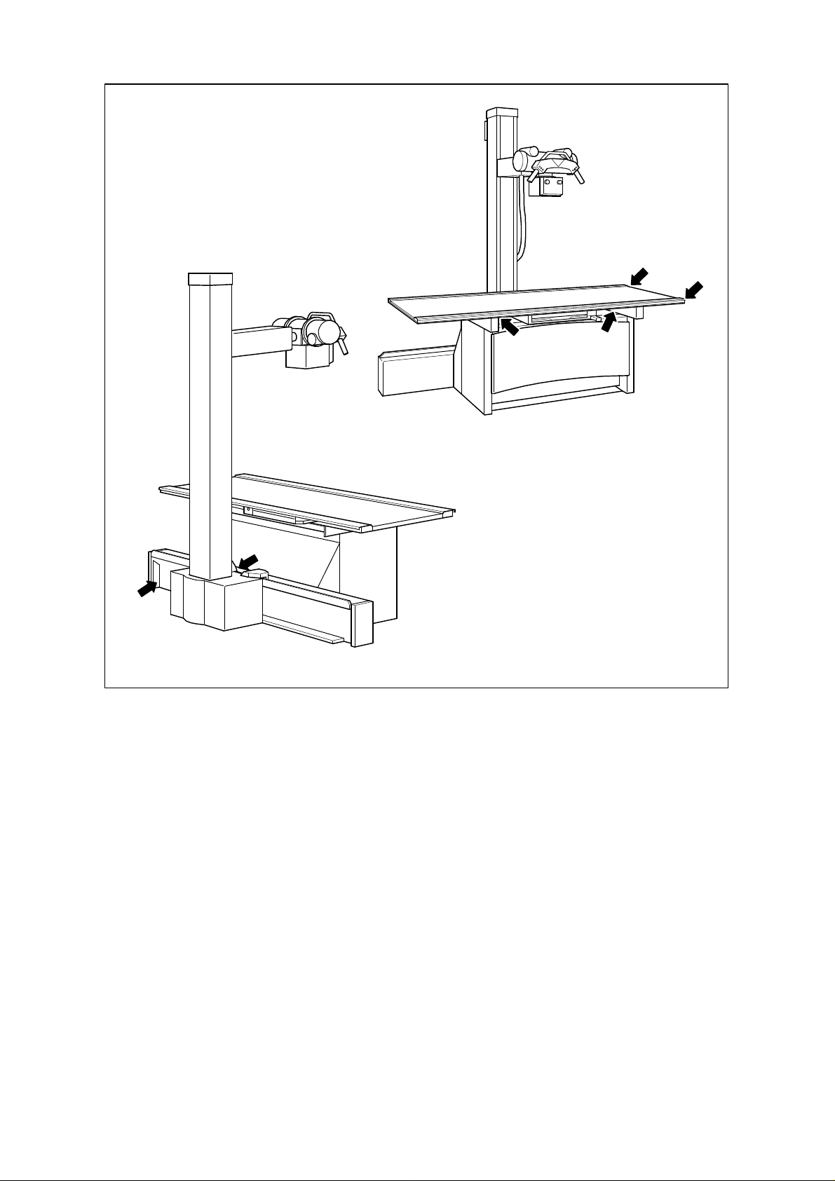
Crush Zones
The highlighted locations in the following sketch represent the danger zones in which the
patient or operator can be injured by crushing or striking.
See following page
0125 7321 - 4 of 20 - 09/99
Rev. 03 1999 Hans Pausch Röntgengeräte Graf-Zeppelin-Str. 1 D-91056 Erlangen ALL RIGHTS RESERVED Ru
Radiation Safety
The equipment does not have any control elements with which radiation can be triggered.
Triggering of exposure is made from the generator radiation-protected location.
The general regulations regarding radiation safety must be observed.
We also recommend:
1. Keep the tube current as low as possible.
2. Keep the radiation field as small as possible.
3. Maintain the max. possible distance.
4. Do not forget to provide radiation protection for the patient.
09/99 - 5 of 20 - 0125 7321
Rev. 03 1999 Hans Pausch Röntgengerätebau Graf-Zeppelin-Str. 1 D-91056 Erlangen ALL RIGHTS RESERVED Ru

Explosion Protection
This product is not intended for use in areas where there is a risk of explosion.
Only those household cleaning products whose gas-air mixture is inflammable may be
used.
Electromagnetic Interference (EMI)
The product meets EMI specifications as defined in EEC Guideline 89/336.
The limit values for measurement of interference per EN 55011, Group 1, Class B and the
requirements for immunity to interference per EN 50082-1, Degrees 2 and 5 are maintained.
Classification per IEC 601-1-1
Depending on the type of protection against electrical shock, the equipment corresponds to
Safety Class 1 and, depending on the degree of protection, Type B.
EC Conformity
This radiographic equipment meets the basic requirements as defined by EEC
Guideline 93/42 of the Committee for Medical Products, per Article 11, Paragr. 3 and the
procedure listed in Appendix II.
The CE symbol is valid only for the product without the radiographic components.
Further information can be obtained upon request from:
Hans Pausch
Röntgengerätebau
Qualitätssicherung
Postfach 28 60
D-91016 Erlangen
Fax: ..49 9131 99 24 22
Environmental Conditions for Operation
Ambient temperature range 10° C to 40° C
Relative humidity in the range 20% to 80%
Ambient pressure in the range 700 hPa to 1100 hPa
Disposal
Legal disposal regulations may exist for this product. To avoid environmental and human
damage, we request that you contact your customer service department before the product
is taken permanently out of operation.
0125 7321 - 6 of 20 - 09/99
Rev. 03 1999 Hans Pausch Röntgengeräte Graf-Zeppelin-Str. 1 D-91056 Erlangen ALL RIGHTS RESERVED Ru

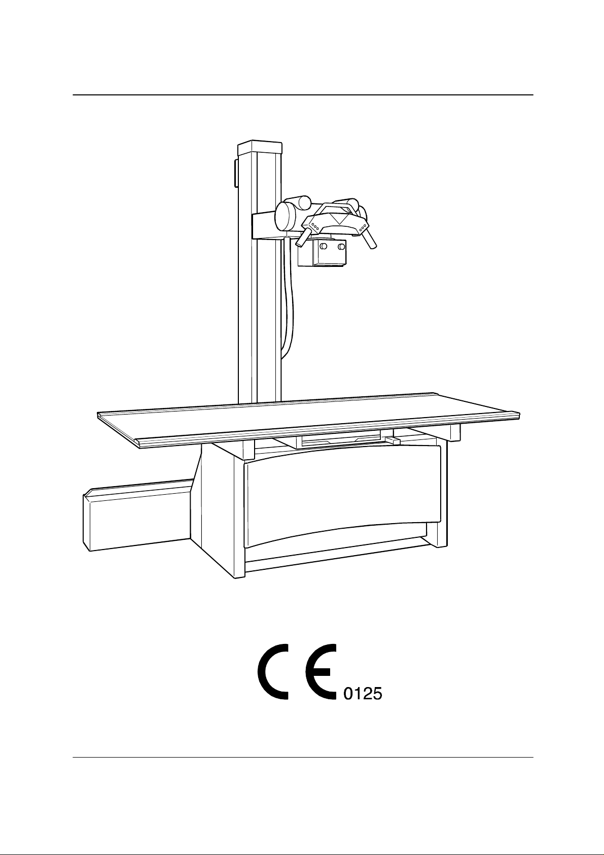
Design Features
- Design
A Tabletop, floating, moved manually, scratch-resistant
B Profile rail, covered, smooth, for attachment of accessories
C Table upper frame
D Adjustable Bucky, moveable
E Table base, stabile, vibration-free
F Rail assembly for column stand
G Footswitch bar
H Vertical carriage with X-ray tube unit support arm
I Column stand, can be pivoted
K X-ray tube unit
L Command arm
M Angle indicator
09/99 - 7 von 20 - 0125 7321
Rev. 03 1999 Hans Pausch Röntgengerätebau Graf-Zeppelin-Str. 1 D-91056 Erlangen ALL RIGHTS RESERVED Ru

General
Brief Description
The equipment system is comprised of a patient table with the Koordinat tabletop and
adjustable Bucky device, as well as a floor-mounted, guided stand column for the X-ray
tube unit, collimator and command arm.
The stabile, vibration-free table base and the rail assembly for the column stand comprise a
single unit.
The large-area, 220 cm-long tabletop is float-mounted, can be moved manually and is
electromagnetically braked. The tabletop is designed for a maximum patient load of 136 kg.
Its wide movement range (60 cm to the left, 50 cm to the right, ± 12 cm transversely) and its
easy movement permit quick, effortless positioning of the patient.
The tabletop has smooth T-slot profile rails on the side which can accept accessories. The
scratch-resistance surface (Resopal) and the covered, smooth rails make the tabletop
especially convenient for the patient and easy to care for.
The adjustable Bucky - suitable for installation of adjustable Buckys from all well-known
manufacturers - can be moved manually in the longitudinal direction under the tabletop and
is braked electromagnetically. The smallest achievable film-skin distance of 70 mm assures
the best geometric illustration relationships. The tabletop, which is only minimally radiationabsorbent (Al attenuation equivalency value below 0.7 mm) thus has only a minimal effect
on dose. The brake for the adjustable Bucky is released by pressing a push-button on the
control grip.
There is a mechanical coupling as an accessory for automatic connection of the adjustable
Bucky and column stand.
The footswitch bar, close to the floor and mounting along the table base permits release of
the tabletop electromagnetic brakes.
The column stand for the X-ray tube unit support arm and the X-ray tube unit is guided in
the rail assembly, parallel to the table longitudinal axis.
The X-ray tube unit with collimator and command arm for the column stand is mounted on a
rigid transverse arm (tube unit support arm) of the vertical carriage. It can be moved
vertically and rotated around the longitudinal axis of the transverse arm. This way, the beam
path can be set vertically, horizontally or obliquely. Each position is locked in place
electromagnetically.
The X-ray tube unit can be pivoted around the vertical column axis with the column stand
and always mechanically engages at 0° (basic position), and at ± 90° (for lateral
exposures).
The standard model of the X-ray tube mount is designed for support flange mounting per
DIN 6836, Form C. The max. weight of the X-ray tube unit with collimator may be 40 kg (88
lbs).
0125 7321 - 8 von 20 - 09/99
Rev. 03 1999 Hans Pausch Röntgengeräte Graf-Zeppelin-Str. 1 D-91056 Erlangen ALL RIGHTS RESERVED Ru

Area of Application
The equipment system is a universal radiographic workstation - for use in private practice,
but also for use in a hospital - for Bucky exposures of excellent quality, primarily on a
reclining patient. Due to the wide range of movement of the tabletop and easy operation, it
is work-saving and patient-friendly. A special cassette holder is available for lateral
exposures. In combination with a Bucky wall stand or with a cassette stand, exposures on a
standing or sitting patient are also possible. The movement of the column stand for the Xray tube unit for a total of ±90° also makes exposures on patient lying on a gurney or in bed
possible.
Because it is not mounted either to the wall or ceiling, the location of the equipment system
can be changed without problem.
Important Note
Proper use of this product requires that operating personnel be familiar with the operating
instructions. They should be carefully studied prior to starting up the equipment. The section
entitled, "Safety-technical Information", should be given particular attention.
Important Note for Operation
The drop brake engages immediately if movement against the end on the column stops at
the top and bottom is too hard.
09/99 - 9 von 20 - 0125 7321
Rev. 03 1999 Hans Pausch Röntgengerätebau Graf-Zeppelin-Str. 1 D-91056 Erlangen ALL RIGHTS RESERVED Ru

Setup
Space Requirement
The unit is designed for stationary operation.
The space required for this is approx. 330 cm x 152 cm.
In addition, a minimum spacing of 20 cm between the column stand and the wall must be
maintained.
Room Height
The height of the column stand is 234 cm. The ceiling height required for installation should
be at least 245 cm. The tabletop of the equipment system has a working height of 75 cm
above the floor.
Connection
The unit is designed for single phase AC current with fixed installation and, depending on
the ordering information, is available in two versions.
The unit is intended only for fixed connection with universal isolation from the power net
(IEC 60 l, Chap. 57.1).
It can be connected to the following nominal line voltage without a pretransformer:
Nominal voltage: 115/230 V AC
Nominal connection current: 2/1 A
Nominal frequency: 50/60 Hz
Nominal connection load: 220 VA
Line Power
Power must be led in over a 30 mA current fault interrupter installed in-house. The room
installation must comply with VDE 0107.
In all countries outside the Federal Republic of Germany, the legally specified national
regulations take priority and must be maintained.
Al Equivalency Value
The attenuation equivalency value of the tabletop (patient table) is ≤ 0.7 mm.
Measured in accordance with:
DIN EN 60601-1-3 at 100 kV and a half-value layer of 3.7 mm Al
and FDA 21 CFR § 1020.30 (n) at 100 kV and a half-value layer of 2.7 mm Al.
0125 7321 - 10 von 20 - 09/99
Rev. 03 1999 Hans Pausch Röntgengeräte Graf-Zeppelin-Str. 1 D-91056 Erlangen ALL RIGHTS RESERVED Ru

Control Elements
Location
1 Green LED goes on when the stand is coupled in the adjustable Bucky
movement range
2 Green LED goes on when tube unit rotation is engaged
3 Green LED goes on when the default SID is reached
4 Button for longitudinal movement
5 Button for vertical movement
6 Button for turning movement
7 Button to release all stand brakes
8 Command arm with handgrips
9 Angle indicator
10 Pivot movement of the column stand by a strong motion in the direction of the
pivot on the command arm
11 Pushbutton for adjustable Bucky
12 Control grip for the cassette tray
13 Footswitch strip
09/99 - 11 von 20 - 0125 7321
Rev. 03 1999 Hans Pausch Röntgengerätebau Graf-Zeppelin-Str. 1 D-91056 Erlangen ALL RIGHTS RESERVED Ru

Explanation of Symbols/Function
Footswitch bar 13
to release the brakes for the floating tabletop. The tabletop
can be moved manually in the longitudinal and transverse
directions while the footswitch bar is held down completely.
The tabletop is engaged in its new working position by
releasing the footswitch bar.
Button 6
to release the brake for rotation movement of the X-ray tube
unit. The X-ray tube unit is engaged in its new working
position by releasing the button.
Button 4
to release the brake for longitudinal movement of the
column stand with the X-ray tube unit. The X-ray tube unit is
engaged in its new working position by releasing the button.
Button 5
to release the brake for vertical movement of the X-ray tube
unit. The X-ray tube unit is engaged in its new working
position by releasing the button.
Button 7
to release all stand brakes. All movements are braked in
their new working position by releasing the button.
0125 7321 - 12 von 20 - 09/99
Rev. 03 1999 Hans Pausch Röntgengeräte Graf-Zeppelin-Str. 1 D-91056 Erlangen ALL RIGHTS RESERVED Ru

Angle indicator 9
displays the tilt angle of the X-ray tube unit to the exposure
subject.
Pilot light, green 1
when lit, indicates when the column stand with X-ray tube
unit is coupled with the adjustable Bucky in the movement
range. When leaving the movement range, the pilot lamp
goes out.
Pivoting the X-ray tube unit 10
The column stand with X-ray tube unit can be pivoted 90° to
the left or right around its longitudinal axis with a strong pull
on both command arm handgrips. It engages in place at
both the 0° and ±90° positions.
Startup
The unit system is immediately operational when it is
switched on.
Emergency Off
When the emergency off switch is installed in the
examination room, the red button of the emergency off
switch must be pressed immediately if there is any danger
for the patient, operating personnel or equipment. The
system may be put back into operation only when the
danger has been clearly eliminated. To do this, turn the red
button on the emergency off switch clockwise.
09/99 - 13 von 20 - 0125 7321
Rev. 03 1999 Hans Pausch Röntgengerätebau Graf-Zeppelin-Str. 1 D-91056 Erlangen ALL RIGHTS RESERVED Ru

Setting the Exposure Position/Exposure
Patient positioning/centering the adjustable Bucky, object, X-ray tube unit
Positioning the patient on the tabletop.
Note
Prior to positioning the patient, move the column stand with
the X-ray tube unit so that the patient cannot injure himself
when he sits or lays down on the tabletop!
Centering the adjustable Bucky
The adjustable Bucky can also be moved to center or
readjust in the exposure area.
Note
This readjustment is necessary when the green lamp for the
automatic stand-adjustable Bucky coupling does not go on.
Centering the exposure subject
Position the exposure subject in the central beam of the Xray tube unit by moving the tabletop. To do this, step down
completely on the footswitch bar 13. The brakes for the
floating tabletop are released. Move the tabletop, release
the footswitch bar; the tabletop is locked in position.
Centering the radiation field
Optimally limit the radiation field (light field!) using the
radiation limiting device in the collimator (collimator
operating instructions).
0125 7321 - 14 von 20 - 09/99
Rev. 03 1999 Hans Pausch Röntgengeräte Graf-Zeppelin-Str. 1 D-91056 Erlangen ALL RIGHTS RESERVED Ru

Preparing an exposure
Insert the cassette. Set the SID. Set the exposure data at
the control console. Check readiness to make an exposure.
Instruct the patient: Please take a breath and hold it! Trigger
the exposure.
Note
Do not forget radiation protective measures for the patient,
lead-rubber apron (gonad protector, etc.)!
Oblique exposure
Appropriately move the column stand out over the coupling
area of the automatic stand-adjustable Bucky coupling.
Position the adjustable Bucky under the exposure subject.
Turn the X-ray tube unit and with the light pointer in the
collimator switched on, center to the middle of the
adjustable Bucky.
Exposure using the Bucky wall stand
Move the tabletop in opposite direction of the wall stand.
Move the column stand in the longitudinal direction to the
wall stand. Rotate the X-ray tube unit 90° (angle indicator!),
switch on the light localizer, move the X-ray tube unit or
adjustable Bucky in the wall stand appropriately in the
vertical direction to center or adjust to the exposure subject.
Lateral exposure
For lateral exposures using the lateral cassette holder (see
also Page 16, Accessories), pivot the column stand 90°,
rotate the X-ray tube unit 90° (angle indicator!). All other
positioning measures have already been described.
09/99 - 15 von 20 - 0125 7321
Rev. 03 1999 Hans Pausch Röntgengerätebau Graf-Zeppelin-Str. 1 D-91056 Erlangen ALL RIGHTS RESERVED Ru

Accessories
Compression band/cassette holder/head rest/handgrips
Compression band
Install
Insert take-up roll B into the wall-side profile rail in the
tabletop. Secure it in the working position using the knob on
the opposite side.
Insert tensioner A into the front rail. Secure the tensioner in
the working position opposite the take-up B with knob C.
Press the release latch F. Unroll the band and stretch it
across the patient.
Wrap the stretch band once around the shaft of the take-up
roll. Insert bow D into the slot of shaft G. Turn knob E and
roll up/tension the compression band.
To release the band
Press release latch F.
0125 7321 - 16 von 20 - 09/99
Rev. 03 1999 Hans Pausch Röntgengeräte Graf-Zeppelin-Str. 1 D-91056 Erlangen ALL RIGHTS RESERVED Ru

Lateral cassette holder
A lateral cassette holder permits exposures using a lateral
beam path. The cassette holder is inserted into the side
profile rails of the table.
Handscrew A: Secures the holder on the tabletop
Handscrew B: Holder pivoting device
Handscrew C: Lateral adjustment of cassette tension
grip (cassette size)
Head stabilizer
The head stabilizer is inserted into the side profile rails of
the table. The stabilizer can be fixed in any desired working
position. Padded supports on the adjustable arms
immobilize the patient's head in the required exposure
position.
Handscrew A: Secures the stabilizer on the tabletop
Handscrew B: Secures the support arm
Handgrips
The handgrips are inserted into the side profile rails of the
tabletop. They can be secured in any desired position and
provide the patient with a secure hold.
Gripscrew A: Secures the working position
Important: The reclining patient may only use the handgrips
provided as a grip. Under no circumstances may be hold on
to the sides of the tabletop.
Automatic Stand-Adjustable Bucky Coupling
The automatic coupling automatically links the adjustable
Bucky with the column stand in its movement range. It
assures automatic centering of the X-ray tube unit to the
center of the film. When this position is left, the green pilot
lamp in the command arm goes off. When moving back into
the movement range of the adjustable Bucky, the green
pilot lamp goes on and coupling or uncoupling takes place
automatically.
09/99 - 17 von 20 - 0125 7321
Rev. 03 1999 Hans Pausch Röntgengerätebau Graf-Zeppelin-Str. 1 D-91056 Erlangen ALL RIGHTS RESERVED Ru

MAINTENANCE
Important Note
As with every piece of technical equipment, this radiographic unit requires regular
maintenance and upkeep to assure the operating reliability of the unit.
Operator Testing
The operator must test the radiographic unit as described below.
If there are malfunctions or other differences from normal operating behavior, switch off the
unit immediately and inform customer service.
The unit may be put back into operation again only after all malfunctions have been
corrected.
Daily Checks
Indicator lamps, operating elements, labels and warning labels.
Weekly Checks
All cables and their connections,
Checks by Customer Service
To achieve problem-free operation of the CS 2000, as well as to achieve safety for patients
and for operating personnel, technical maintenance must be performed by customer service
in intervals of 12 months.
See ”Technical Maintenance" in the installation instructions.
As part of this, it is required that the steel cable in the stand be replaced every 3 years.
Caution
If there are parts failures which affect the safety of the unit, original replacement parts must
be used.
We recommend that when this work is performed, written confirmation be obtained about
the type and extent of the work, and if applicable, with a statement about any changes that
have been made to nominal data or about the working range, as well as with the date,
name of the company performing the work and a signature.
CLEANING
Switch off the system prior to cleaning it.
Plastic surfaces may be cleaned only with a solution of soapy water because other agents
(e.g. with high alcohol content) can dull or cause cracking of the surface.
No caustic, solvent or scouring cleansers or polishes may be used. Water or other liquids
may not get into the unit to avoid short-circuits in the electrical installation and corrosion of
parts.
0125 7321 - 18 von 20 - 09/99
Rev. 03 1999 Hans Pausch Röntgengeräte Graf-Zeppelin-Str. 1 D-91056 Erlangen ALL RIGHTS RESERVED Ru

Painted parts and aluminum surfaces may be moistened only with a damp cloth and a mild
cleaning agent and wiped down with a soft cloth. Chromed parts may only be wiped down
with a soft, dry cloth.
DISINFECTION
Switch off the system prior to disinfecting it. Only those disinfection methods that meet the
applicable regulations and guidelines as well as explosion safety may be used. No caustic,
solvent or gaseous disinfectants may be used. Spray disinfection is not recommended
because if it is, disinfectants can get into the radiographic unit.
EEC Guideline 93/42 Regarding Medical Products
Article 12
Special Procedure for Systems and Treatment Equipment
Differing from Article 11, this article applies for systems and treatment equipment.
(2) Every natural or legal person who assembles products which bear the CE symbol, with
the intention of putting them into use in the form of a system or as treatment equipment
corresponding to their specified purpose and within their intended defined application, must
provide a statement of content that
a) in mutual agreement, they have tested the products in accordance with the
manufacturer's instructions and have performed the work steps in accordance with these
instructions;
b) they have packaged the system or treatment equipment and have provided specific user
instructions, including detailed manufacturer instructions;
c) the entire procedure was internally monitored and checked in an appropriate manner.
If the conditions as stated in Paragraph 2 have not been met, as would be the case when
the system or the treatment equipment includes products which do not bear the CE symbol,
or when the selected combination of products no longer corresponds to its original intended
purpose, the system or treatment equipment shall be considered a separate product and,
as such, is subject to the detailed specifications of Article 11.
The operator is responsible for maintenance of and compliance with national differences in
EC countries!
09/99 - 19 von 20 - 0125 7321
Rev. 03 1999 Hans Pausch Röntgengerätebau Graf-Zeppelin-Str. 1 D-91056 Erlangen ALL RIGHTS RESERVED Ru

Placement of Model Labels
Datum
89
Labeling
Röntgengerätebau
D-91065 Erlangen
Graf-Zeppelin-Str. 1
Type
Fabr. Nr.
Spanng.
Frequenz
Strom
Made in Germany
Volt
Hertz
Ampére
01
25
We reserve the right to make changes resulting from continuing technical developments.
TV/Ru
0125 7321 - 20 von 20 - 09/99
Rev. 03 1999 Hans Pausch Röntgengeräte Graf-Zeppelin-Str. 1 D-91056 Erlangen ALL RIGHTS RESERVED Ru
 Loading...