

OPERATING INSTRUCTIONS Cosmos-2
______________________________________________________________________________________________________________
___________________________________________________________________________________________________
English Edition
08/98 -1 of 18- 0380 7321
Revision 05 © 1998 Hans Pausch Röntgengerätebau Graf-Zeppelin-Str.1 D-91056 Erlangen ALL RIGHTS RESERVED Ru

CONTENTS Page
Important Note 3
Technical Safety Procedures
- Regulations 3
Product Safety
- Electrical safety 4
- Mechanical safety 4
- Danger of Injury 4
- X-Ray Protection. 5
- Explosion protection 6
- Interference suppression 6
- Classification of product 6
- EC Conformity 6
- Environment condition 6
- Disposal of equipment 6
Design Features
- Conception 7
General
- Brief Description 8
- Range of Application 8
Installation
- Floor Space Required 9
- Room Height 9
- Power/Mains 9
Operating Elements
- Arrangement 10
- Meaning of Symbols/Function 11
- Operation 12
- Application examples 13
- Accessories 14
Maintenance
- Important note 16
- Operators service and maintenance 16
- Periodic maintenance 16
- Cleaning 16
- Disinfection 17
- The Council Directive 93/42EEC on Medical Devices 17
Name Plate Location:
- Labeling: 18
0380 7321 -2 of 18- 08/98
Revision 05 © 1998 Hans Pausch Röntgengerätebau Graf-Zeppelin-Str.1 D-91056 Erlangen ALL RIGHTS RESERVED Ru

Important Note:
To ensure proper operation of this product it is essential that the service personnel is familiar with the "Operating Instructions" which should be studied carefully
before use.
Special attention is to be given to the chapter "Safety Notes"
The equipment must be used in accordance with the safety procedures described below, and must not be used for purposes other than those for which it
was designed. The equipment may only be used by persons having recognised
qualification, including adequate training in radiation protection, authorising them to
perform the examination or treat ment carried out.
It is the responsibility of the user to ensure that the government regulations are
observed in the operating conclitions of the equipment.
Technical safety note:
Regulations
If statutory regulations govern the operation of the above equipment, it is the
responsibility of the operator to ob serve them.
For the safety of patients, operators and others, as well the efficient functioning
of the equipment it is necessary to have periodic service inspections at 12-month
intervals according to the maintenance schedule. Please apply to your service organisation for inspection and maintenance.
Inspections intervals must by all means meet the requirements of the respective
legislation or government regulations.
Changes and additions to the product must comply with the relevant legislation
as well as with the accepted standards of good manufacturing practice.
As manufacturer of electromedical systems, we assume responsibility for the
safety of the equipment only if maintenance, repairs and changes are carried out
exclusively by us or third parties expressly authorised by us to do so, and if defective parts relating to the safety of the equipment are replaced by genuine spare
parts.
We recommend that the service personnel is being asked to issue a certificate
specifying the kind and extend of work . Also the certificate should show the date
of repair, the name of the service company and the signature of the technician.
Before operating the equipment, the operator must check all devices concerning
the safe and efficient functioning.
If the user of this equipment likes to combine the unit with other units, components or assemblies and this can not be made clear from the technical data, he
08/98 -3 of 18- 0380 7321
Revision 05 © 1998 Hans Pausch Röntgengerätebau Graf-Zeppelin-Str.1 D-91056 Erlangen ALL RIGHTS RESERVED Ru

must question us as manufacturer or another expert to make sure that the safety
of the patients and operator is given by the planned combination.
Product Safety
Electrical safety
Only trained service personnel are permited to remove covers and panels from the
x-ray equipment .
In the Federal Republic of Germany, the electrical installation of rooms used for
medical purposes must conform to the provisions of the VDE Standard 0107. In all
other countries, the provisions of the applicable local laws and regulations have
priority.
Mechanical safety
It is the responsibility of the operator to ensure safety of patient while the unit is
in operation by visual check, proper patient positioning, and use of devices that
are provided.
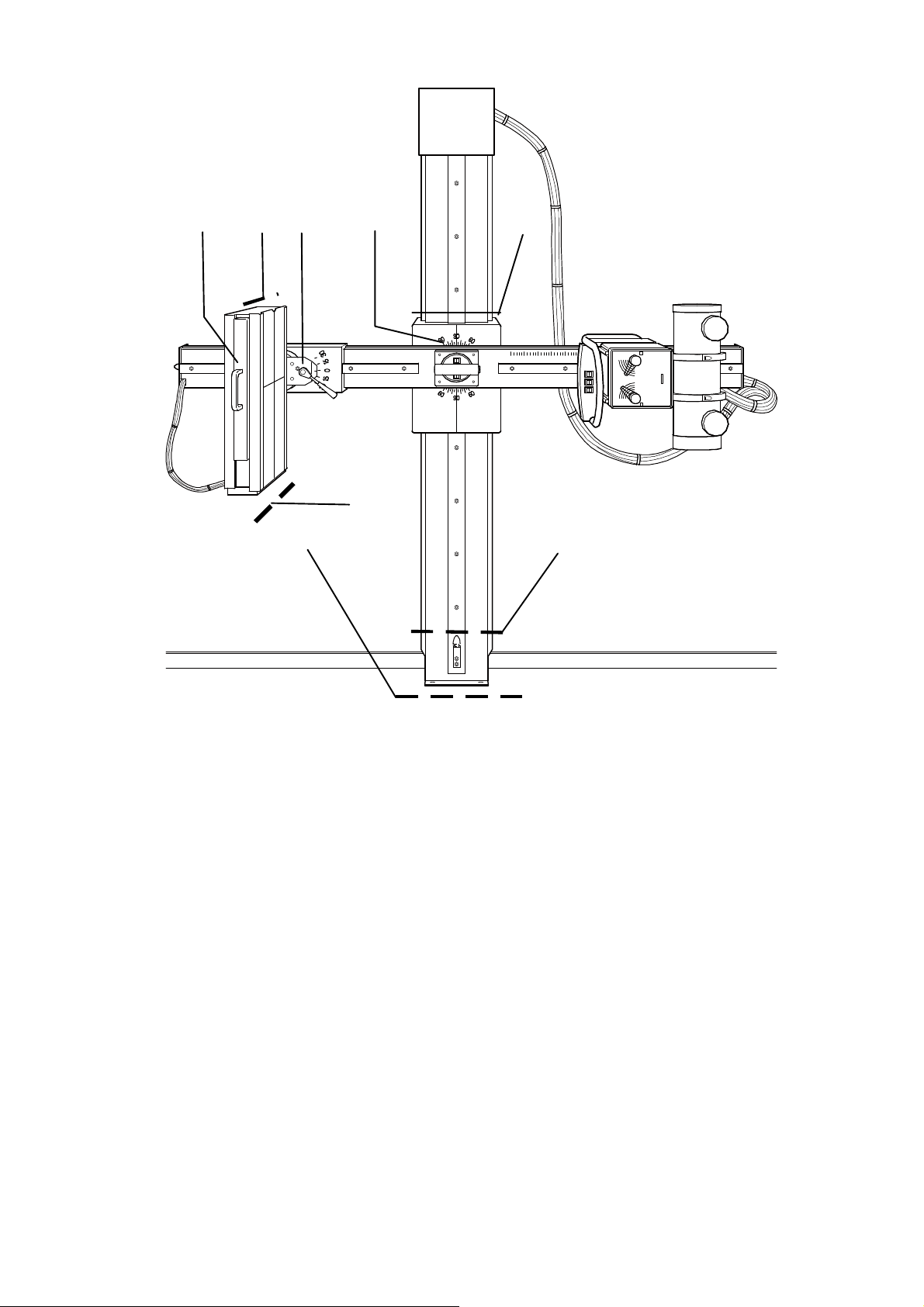
Danger of injury
The solid black arrows and dotted lines in the illustration show areas which present
potential Danger of Injury to operating personal and patient from the equipment
motion.
See next page.
0380 7321 -4 of 18- 08/98
Revision 05 © 1998 Hans Pausch Röntgengerätebau Graf-Zeppelin-Str.1 D-91056 Erlangen ALL RIGHTS RESERVED Ru
Ê Ê Ê
Ê
Ê Ê
Ê
Ê
X-Ray Protection.
The unit has no controls with which radiation could be triggered.
Exposure is triggered only from the radiation-protected location of the generator.
The general radiation-protection measures must be observed.
In addition, we recommend the following:
1 Set the tube current as low as possible .
2 Limit the radiation field to the maximum possible extent.
3 Keep as fare away as possible.
4 Provide radiation protection for the patient.
08/98 -5 of 18- 0380 7321
Revision 05 © 1998 Hans Pausch Röntgengerätebau Graf-Zeppelin-Str.1 D-91056 Erlangen ALL RIGHTS RESERVED Ru

Explosion Protection
This equipment is not designed for use in areas where explosion hazard can take
place.
Only skin cleansing agents may be used which form non-explosive mixtures with
air.
Interference Suppression
The equipment complies with the EMC-requirements of the guideline 89/336 EWG.
of
* Special board International Electronic Commission (IEC) This unit complies to
EN 55011 and the reference value is according EN 55011 Group 1 Class B the in-
ternational electrotechnical committee (IEC).
Classification of product
The equipment complies to the protection degree of Class 1 and for protection
against electric shock Type B.
EC Conformity
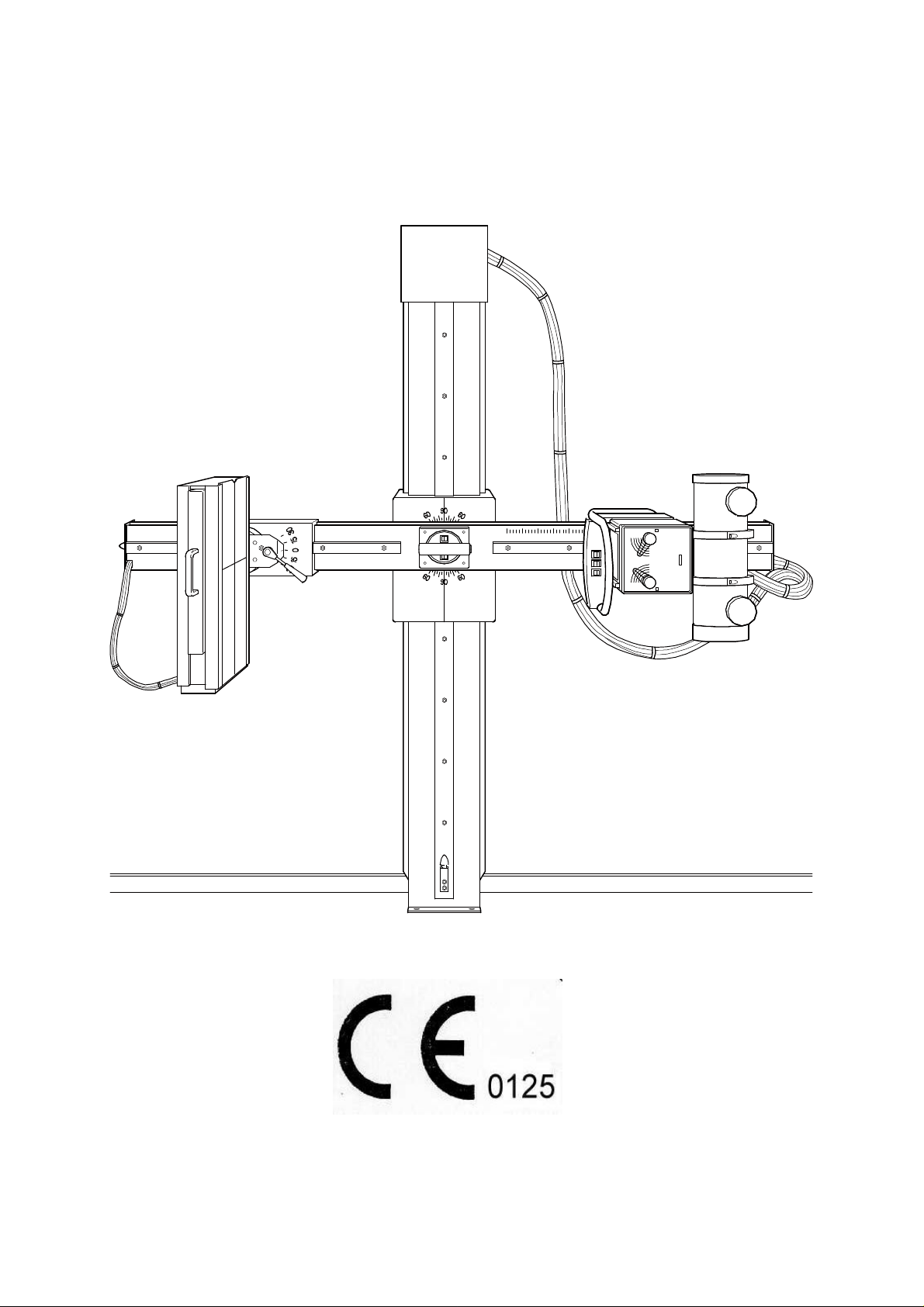
The Cosmos-2 to which this declaration relates fulfills the essential requirements
for safety of medical electrical equipment and follows the provisions of Medical
Device Directive 93/42 EEC part 11 para. 3 according the procedure in annex II.
The CE-Mark is only applicable for the product without X-ray components and
Bucky.
The declaration of EC-conformity can be sent to you by request:
Write to:
Hans Pausch
Röntgengerätebau
c/o Quality Assurance Sys. Mgr.
Postfach 28 60
D-91016 Erlangen
Fax #: ..49 9131 99 24 22
Enviroment Condition
Surrounding temperature range 10° C to 40° C
Humidity 20% to 80%
Atmospheric pressure 700 hPa to 1100 hPa
Disposal of equipment
For this equipment there could existlegal disposal regulations. To avoid environ-
mental and personal injury contact your service personnel before shutting down the
equipment.
0380 7321 -6 of 18- 08/98
Revision 05 © 1998 Hans Pausch Röntgengerätebau Graf-Zeppelin-Str.1 D-91056 Erlangen ALL RIGHTS RESERVED Ru

Design Features
Component Designations
L F
A D
B E
K
C
G
H
I
A Column
B Vertical Carriage
C Swivel Arm
D Controls
E SID Scale
F X-Ray Tube with Collimator
G Brake for Bucky Tilt
H Bucky
I Cassette Tray
K Central Control Unit
L Scale for Bucky Angulation
08/98 -7 of 18- 0380 7321
Revision 05 © 1998 Hans Pausch Röntgengerätebau Graf-Zeppelin-Str.1 D-91056 Erlangen ALL RIGHTS RESERVED Ru

General
Description
The X-Ray tube is fixed in centerline to the center of the Bucky.
The Source-Image Distance (SID) is motorized adjustable in a range from 1 m to
2 m .
The Swivel Arm is bearing revolving mounted and can be fixed in any position.
The Rotational Movements are locked electromagnetically.
The COSMOS-2 examination unit is universally usable for taking exposures of
standing, sitting or recumbent patients.
The Bucky - and X-Ray tube carriage run on ball bearings over the guide rails of
the swivel arm.
The Vertical Carriage is guided on ball bearings in its vertical direction of the
column and locked in place electromagnetically.
The Bucky unit can be turned 45 degrees and a mechanical detent is provided at
zero degrees position.
The Patient table is an independent unit, easily moveable on castors. The twin
castors can be locked.
Description
The COSMOS-2 X-Ray unit is a universal work station for doctors practices as
well as for hospitals with high-quality exposures. Especially the large vertical
movement and the simple rotation together with the easy operation makes the
COSMOS-2 patient- and operating friendly.
0380 7321 -8 of 18- 08/98
Revision 05 © 1998 Hans Pausch Röntgengerätebau Graf-Zeppelin-Str.1 D-91056 Erlangen ALL RIGHTS RESERVED Ru

Installation Requirements
Floor Space
The system is designed for stationary operation. The approx. floor space required measures 240 x 130 cm; with patient table 340 x 220 cm.
Roomheight
The required roomheight should be 285 cm to work without problems.
Power
The system is equipped for single phase alternating current with fixed installation.
The system corresponds to nominal ratings as follow:
Nominal Voltage: 115 / 230 V
Nominal Current: 2 / 1 A
Rated Frequency: 50 / 60 Hz
Nominal Capacity: 230 VA
Mains
The mains connection requires a 30 mA circuit breaker to be installed by the cus-
tomer. The electrical installation must meet the relevant legislation, e.g. VDE
0107, IEC/SC 62A.
AL-equivalent
The weakening equivalent of the table top (patient pos. table top) is £ 0,6 mm.
The weakening equivalent of the Bucky - Front plate £ 0,55 mm.
According to:
DIN EN 60601-1-3 with 100 kV and HWS 3,7 mm AL
and FDA 21 CFR § 1020.30 (n) with 100 kV and HWS 2,7 mm AL.
08/98 -9 of 18- 0380 7321
Revision 05 © 1998 Hans Pausch Röntgengerätebau Graf-Zeppelin-Str.1 D-91056 Erlangen ALL RIGHTS RESERVED Ru

Operating Controls
Arrangement
12
10
7
11 5
8 1
6 2
9 3 4
1 Momentary switch for swivel arm rotation
2 Switch for SID adjustment
3 Switch for vertical movement
4 Indicator light *
5 Switch for vertical movement
6 Switch for SID adjustment
7 Momentary switch for swivel arm rotation
8 Brake lever for Bucky tilt
9 Cassette tray handle
10 Operating controls for Collimator (ref. to manufacturers inst.)
11 Main control handle
12 Control arm
· on request
0380 7321 -10 of 18- 08/98
Revision 05 © 1998 Hans Pausch Röntgengerätebau Graf-Zeppelin-Str.1 D-91056 Erlangen ALL RIGHTS RESERVED Ru

Meaning of Symbols /Function
Momentary switch A or E
to unlock the rotational brake.
Press the momentary switch A or E, move the
swivel arm in desired working position. Release the switch and the swivel arm will be
locked in place.
Momentary switch B or F
for motorized adjustment of the SID.
Press the momentary switch B or F to increase
or decrease the SID. The motor will stop
automatically in its end position or when the
switch is released in desired position.
Switch C
A
B
to release the vertical lock.
Press switch C. Make required height ad
just-
ment and put the switch in off position.
Note: The switch will light up when put into
"vertical brake off" position.
Momentary switch G
to release the vertical lock.
Press the momentary switch G, move the
swivel arm in desired working position. Release
the switch and the swivel arm will be locked in
place.
Brake lever H
E
F
C
G
to release the Bucky lock.
Loosen brake lever H in c.c.w. direction. The
Bucky can now be SA ± 30 degrees. Turn
H
brake lever in c.w. direction to lock Bucky in
desired position.
08/98 -11 of 18- 0380 7321
Revision 05 © 1998 Hans Pausch Röntgengerätebau Graf-Zeppelin-Str.1 D-91056 Erlangen ALL RIGHTS RESERVED Ru

Operation
The unit is ready for operation when switched on.
Emergency-off
Provided an emergency switch has been installed in the
examination room, the red switch button must be pushed
immediately in case of danger for patients, operating personnel, or equipment. Only after positive elimination of the
danger, turn the red emergency off switch clockwise to
resume operation.
General
Upon voltage loss, the vertical movement of the unit is released.
Important note
The safety brake will be effected immediately in case that it
will be driven to hard against the end limit stops from the
top and from below of the column.
0380 7321 -12 of 18- 08/98
Revision 05 © 1998 Hans Pausch Röntgengerätebau Graf-Zeppelin-Str.1 D-91056 Erlangen ALL RIGHTS RESERVED Ru

Application examples
08/98 -13 of 18- 0380 7321
Revision 05 © 1998 Hans Pausch Röntgengerätebau Graf-Zeppelin-Str.1 D-91056 Erlangen ALL RIGHTS RESERVED Ru

Accessories
Compression Belt / Head Supports / Hip Clamps / Table Mattress
Compression Belt
Fastening and application:
Slide support frame B into profile rail at wall side or into
Bucky profile rail. Turn knob screw to clamp in position.
Slide tightener A into front profile rail ( operator side ).
Turn hand screw C to clamp in working position opposite
of B
Guide belt through complementary frame and once
around frame bar. Fix belt bracket D into slot of shaft G.
Turn ratchet mechanism E to tighten belt.
Press ratchet mechanism F. Unroll belt and stretch across
patient.
Untightening:
Press locking lever F
0380 7321 -14 of 18- 08/98
Revision 05 © 1998 Hans Pausch Röntgengerätebau Graf-Zeppelin-Str.1 D-91056 Erlangen ALL RIGHTS RESERVED Ru

Head Supports / Hip Supports
The head supports slide into profile rails of the
table or Bucky. The supports can be clamped
in any position desired. The patients head is
fixed to the appropriate exposure position by
cushioned plates on adjustable bars.
Hand screw A: Clamping Head Supports to
table top or Bucky.
Hand screw B: Clamping of head holder
Patient positioning table
The patient positioning table can be moved easily
on steering rolls independent of the equipment and
can be arrested in each direction with the two dou-
ble stop rolls A.
CC
B
Patient positioning pad for patient positioning
table
The patient positioning pad is radiotransparent.
Used for comfortable positioning of the patient
on the table top.
Cassette holder for hang over
Put in cassette holder for cassettes 13x18 until
35x43 over the front plate of the Bucky in both
profile rails.
A
08/98 -15 of 18- 0380 7321
Revision 05 © 1998 Hans Pausch Röntgengerätebau Graf-Zeppelin-Str.1 D-91056 Erlangen ALL RIGHTS RESERVED Ru

Maintenance:
Important note:
Like all technical equipment, this unit requires also a regular maintenance service
to increase the safety of the equipment.
Operator’s service and maintenance
The operator has to check the x-ray equipment for defects as listed below:
In case of functional defects or other deviations from the normal operation the
equipment has to be switched off at once and the service company has to be in-
formed.
The equipment can not be used before all defects have been eliminated.
Daily routine checks
Check indicator light and operating elements for proper functioning.
Weekly checks
Check all cables and their connections for treaces of wear.
Periodic maintenance
For trouble-free operation of the Cosmos-2 as well as safety for patient and user it
is necessary to carry out a technical maintenance from the service company every
12 months.
Please see „technical maintenance“ of the mounting instruction.
The steel rope of the column has to be replaced every three years.
Attention:
In case of failure from components, which can limit the safety of the equipment,
original spare parts have to be used.
We recommend that the service personnel is being asked to issue a certificate
specifying the kind and extend of work that was done. Also the certificate should
show the date of repair, the name of the service company and the signature of the
technician.
Cleaning:
The equipment must be switched off before cleaning. Plastic surface should only
be cleaned with mild soap. Do not use strong cleaners or solvents as they will
damage the finish or blur the lettering.
0380 7321 -16 of 18- 08/98
Revision 05 © 1998 Hans Pausch Röntgengerätebau Graf-Zeppelin-Str.1 D-91056 Erlangen ALL RIGHTS RESERVED Ru

At least once a month external parts and exposed tracks on which rollers move
should be wiped to remove foreign material that may have accumulated.
DO NOT USE A DAMP CLOTH.
Wipe the tracks with a cloth lightly soaked with light machine oil or WD-40.
To protect the finish, polish the equipment with PURE liquid paste wax. Do not use
wax containing a cleaning substance. Polish all enameled metal surfaces.
Disinfection:
The equipment has to be switched off before disinfection. Only disinfection meth-
ods can be used that correspond to the relevant regulations and rules as well as
the protection for explosion.
Spray disinfection is not recommended because it can get in the inside of the x-ray
equipment.
The Council Directive 93/42/EEC on Medical Devices
Article 12
This document is revised at the moment by the council.
However the Article 12 must be followed by the company or the legal person who
put this X-ray unit into work.
The user is responsible for compliance and implementation of national deviations
in the EC.
08/98 -17 of 18- 0380 7321
Revision 05 © 1998 Hans Pausch Röntgengerätebau Graf-Zeppelin-Str.1 D-91056 Erlangen ALL RIGHTS RESERVED Ru

Name Plate Location:
Labeling:
Specifications are subject to change without notice. TV/Ru
0380 7321 -18 of 18- 08/98
Revision 05 © 1998 Hans Pausch Röntgengerätebau Graf-Zeppelin-Str.1 D-91056 Erlangen ALL RIGHTS RESERVED Ru
 Loading...