

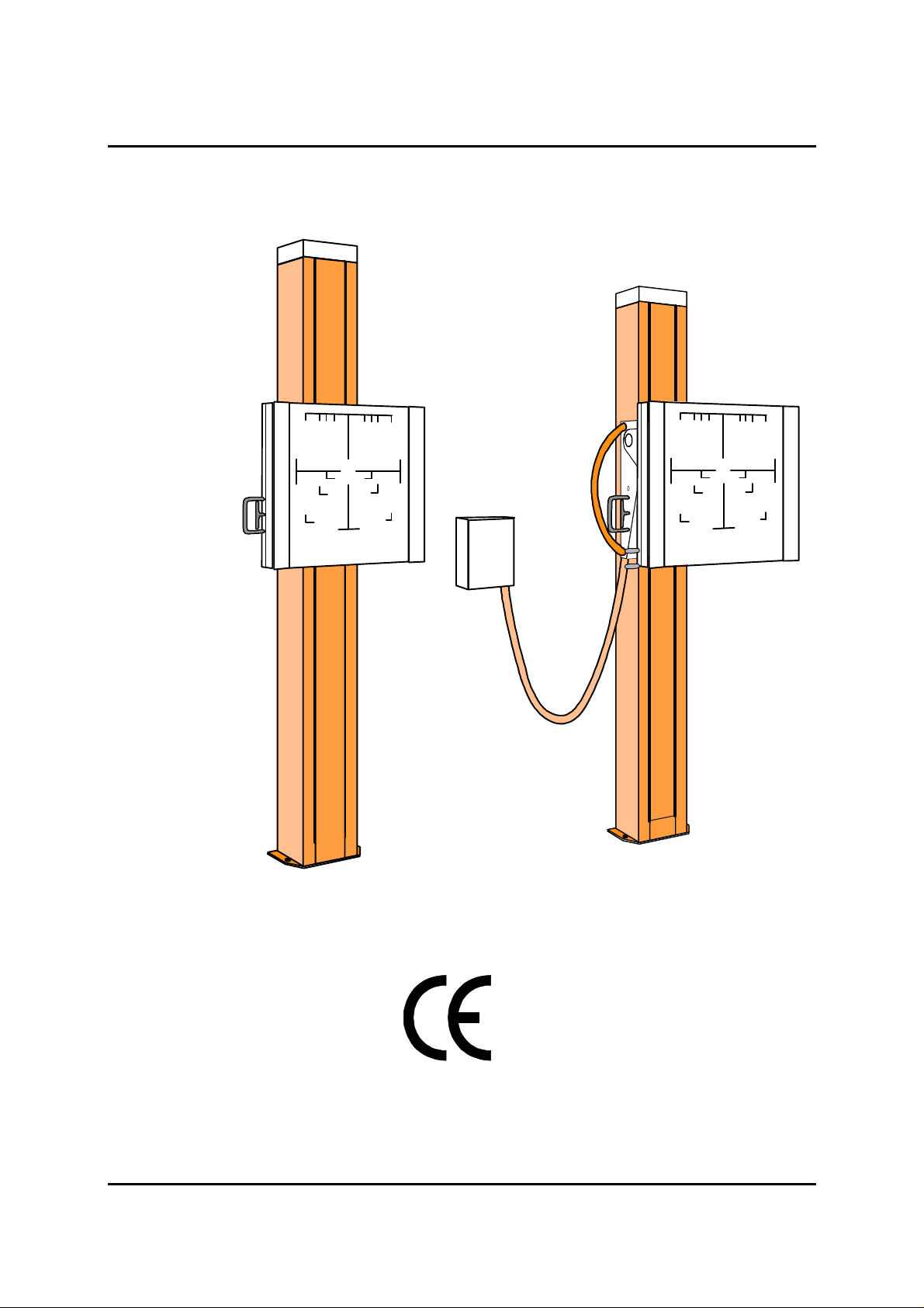
MOUNTING INSTRUCTIONS BS 2000
English Edition
06/98 - 1of 26 - 0370 7221
Rev. 01 © 1998 Hans Pausch Röntgengerätebau Graf-Zeppelin-Str.1 D-91056 Erlangen ALL RIGHTS RESERVED Ru

TABLE OF CONTENTS Page
1. General safety notes
1.1 Technical data 3
1.1.1 Compatibility 3
1.1.2 Climatic conditions 3
1.2 Measurements and weights 4
1.3 Scope of delivery 4
1.4 Component designation 5
1.5 Dimensions of components version V 6
1.6 Dimensions of components version VK 7
1.7 Site preparation 8
1.8 Tools 8
1.9 Test equipment 8
2. Installation
2.1 Installation of Bucky-unit version V 9
2.2 Installation of Bucky-unit version VK 9
2.3 Installation at the wall 10
2.4 Installation without wall 11
2.5 Installation of the covers 11
2.6 Installation of the patient armrests 12
2.7 Installation of counterbalance 12
3. Reconstruction of handles
3.1 Handle version V 13
3.2 Handle version VK 13
3.3 Installation of the spacer version V 14
4. Electrical diagrams 16
5. Preventive Maintenance
5.1 Exchange of wire rope 17
5.2.1 Spare parts 18
5.2.2 Spare parts 19
5.2.3 Spare parts 20
5.3 Spareparts List 21
5.4 Maintenance Certificate 24
5.5 Name Plate Location 25
0370 7221 - 2 of 26 - 06/98
Rev. 01 © 1998 Hans Pausch Röntgengerätebau Graf-Zeppelin-Str. 1 D-91056 Erlangen ALL RIGHTS RESERVED Ru

1. General safety notes
In the Federal Republic of Germany, the electrical installation of rooms for medical purposes must conform to the provisions VDE Standard 0107. In all other countries the national requirements have to be observed. Check the installation layout plan.
During the installation it is important to check that all protective ground wire connections
provided by the manufacturer are properly made before the equipment is started up.
The protective ground wires between the individual system components and the power
supply are connected as shown in the wiring diagram.
Regulation of professional associations concerning safety and accident prevention has to
be observed. No work may be performed on parts carrying a voltage higher than 42 V.
If it is necessary to turn on the power for execution of movements of the equipment in the
course of installation procedure, it must be shut down immediately after completion of
these movements.
1.1 Technical data
1.1.1 Compatibility
These mounting instruction is valid for Bucky-units BS 2000 and all versions of them.
The columns carry all customary in trade Bucky-units.
The columns will be supplied with the brake handles at the left hand side.
It is possible to exchange the handles in the field if necessary. The procedure of exchang-
ing the handle will be described in section 3.
1.1.2 Climatic conditions
During regular work:
Temperature: 10° C to 40° C
Humidity: 20% to 80%
Air pressure: 700hPa to 1100hPa
During transport:
Temperature: -25° C to 70° C
Humidity: 5% to 95%
Air pressure: 700hPa to 1100hPa
06/98 - 3of 26 - 0370 7221
Rev. 01 © 1998 Hans Pausch Röntgengerätebau Graf-Zeppelin-Str.1 D-91056 Erlangen ALL RIGHTS RESERVED Ru

1.2 Measurements and weights
Measurements With shipping box Without shipping box
Version V 2340 x 750 x 650 mm 2220 x 650 x 420 mm
Version VK 2340 x 750 x 850 mm 2220 x 650 x 620 mm
Weights With shipping box Without shipping box
Version V 190 kg 150 kg
Version VK 240 kg 195 kg
Options:
Bucky P 13,0 kg
Front cover with profilrails for accessories 5,2 kg
Support triangle for installation without wall incl. fixing material. 12,5
Spacer incl. additional counterweights (only version V) 10,0 kg
Patientstretching-rest 2,5 kg
Patient armrests 1,1 kg
Compression belt device 2,0 kg
Cassette holder 2,0 kg
Babyx holder 3,9 kg
1.3 Scope of delivery
Standard:
Column with counterweight and Bucky carrier incl. Fixing material for wall- and floor-fixing.
Adaptation parts for fixing the Bucky-unit.
Wall connection box incl. corrugated hose and fixing material for wall connection box.
Options:
Support triangle for installation without wall incl. fixing material.
Front cover with profilrails for accessories
Patient armrests
Patient stretching-rest
Babyx holder
Spacer incl. additional counterweights (only version V)
High distance measurement device
0370 7221 - 4 of 26 - 06/98
Rev. 01 © 1998 Hans Pausch Röntgengerätebau Graf-Zeppelin-Str. 1 D-91056 Erlangen ALL RIGHTS RESERVED Ru
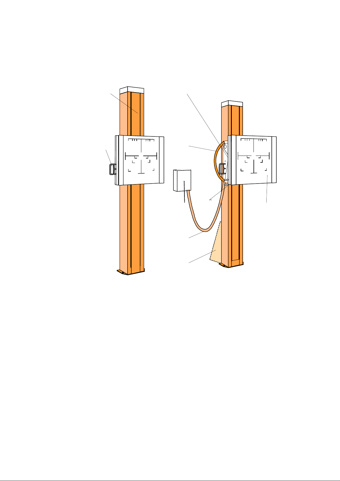
1.4 Component designation
A I
B C
D
E G
E
H
A Column
B Brake handle
C Patient rests
D Tilting handle
E Corrugated hose
F Wall connection box
G Front cover with profilrails for accessories
H Support triangle
I Display of tilting angle
K Spacer (only version V)
L Patient stretching-rest
06/98 - 5of 26 - 0370 7221
Rev. 01 © 1998 Hans Pausch Röntgengerätebau Graf-Zeppelin-Str.1 D-91056 Erlangen ALL RIGHTS RESERVED Ru
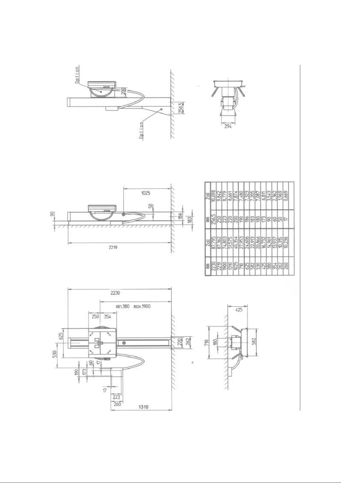
1.5 Dimensions of components version V
0370 7221 - 6 of 26 - 06/98
Rev. 01 © 1998 Hans Pausch Röntgengerätebau Graf-Zeppelin-Str. 1 D-91056 Erlangen ALL RIGHTS RESERVED Ru
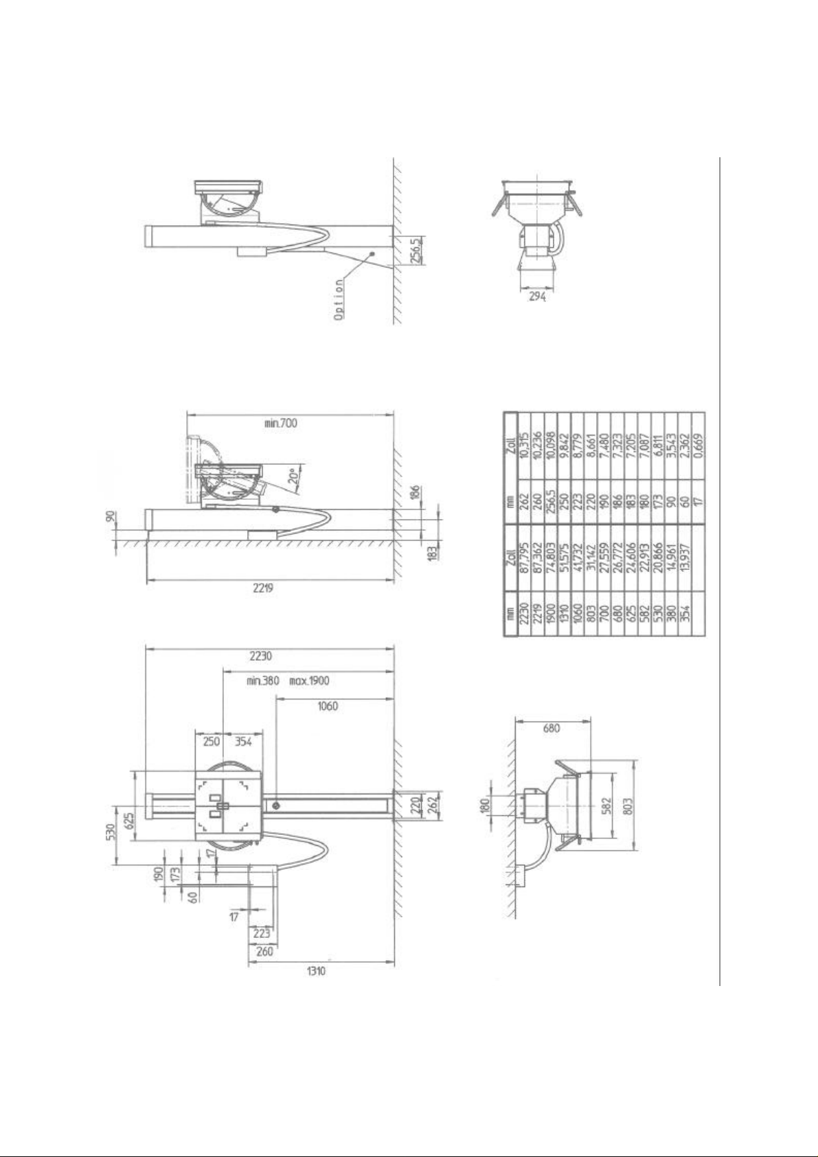
1.6 Dimensions of components version VK
06/98 - 7of 26 - 0370 7221
Rev. 01 © 1998 Hans Pausch Röntgengerätebau Graf-Zeppelin-Str.1 D-91056 Erlangen ALL RIGHTS RESERVED Ru

1.7 Site preparation
The electrical data have to correspond to the Bucky-unit installed.
For the columns only the respective ground wire connection is required.
The mounting points on mounting surface have to be suitable for tensile strength of 2400 N
each (concrete class B 150 DIN 1045 or other national requirements, if the supplied fixing
material will be used).
The fixing drillings have to be inserted at the floor 12 mm , at the wall 10 mm and at the
wall connection box 8 mm as shown in diagrams 1.5, or 1.6.
Depending on the version the cable for the Bucky-unit and the measurement chamber have
to be installed to the wall connection box or to the Bucky-unit as shown in cabling diagram
of installation.
A set of cables including hose and wall connection box are scope of delivery.
1.8 Tools
Service standard tool kit
1.9 Test equipment
Spirit level
0370 7221 - 8 of 26 - 06/98
Rev. 01 © 1998 Hans Pausch Röntgengerätebau Graf-Zeppelin-Str. 1 D-91056 Erlangen ALL RIGHTS RESERVED Ru

2. Installation
2.1 Installation of Bucky-unit version V
Unpack the individual parts and check for completeness. If necessary compare with scope
of delivery section 1.3 or order.
Check that all parts are not damaged.
Note: If the application requires the using from right hand side the exchange of the brake
handle should be done first.
The following steps have to be carried out by the column in the horizontal position.
Pull the connection cable for the Bucky-unit and if necessary the cable for the measurement
chamber through the appropriate openings.
Install the side cover (Fig. 1 Pos. 4) and fix it with the shackle. (If needed install the spacer).
Place the Bucky-unit between the covers and fix it with 2 bolts (Pos.2) each above and
below to the carrier or spacer.
Install the covers (Pos.3) each with 4 bolts (Pos.1) and washers on the carrier.
Fig. 1 Fig. 2
Connect the Bucky cable and if necessary the cable for the measurement chamber as descriped in the documentation of the Bucky-unit.
Install the front panel (Fig.2 Pos.1) and the cable cover below (Pos.2).
Place two blocks of wood or similar under the column and remove the transport safety fixing
bars from above and below both sides of the pallet.
06/98 - 9of 26 - 0370 7221
Rev. 01 © 1998 Hans Pausch Röntgengerätebau Graf-Zeppelin-Str.1 D-91056 Erlangen ALL RIGHTS RESERVED Ru

2.2 Installation of Bucky-unit version VK
Unpack the individual parts and check for completeness. If necessary compare with scope
of delivery section 1.3 or order.
Check that all parts are not damaged.
Attention: Do not operate the tilting handle in horizontal position of the column. Accident
prevention !
Note: If the application requires the using from right hand side the exchange of the handle
should be done first.
The following steps have to be carried out by the column in the horizontal position.
Pull the connection cable for the Bucky-unit and if necessary the cable for the measurement
chamber through the appropriate opening.
Install the side cover (Fig.3 Pos.5) and fix it with the shackle. (If needed install the spacer).
Place the Bucky-unit between the covers and fix it with 2 bolts (Pos.2) each to the carrier.
Install the cover (Pos.3) and the fixed part of the tilting handle (Pos.4) with 4 bolts (Pos.1)
and washers each on the carrier.
Connect the Bucky cable and if necessary the cable for measurement chamber as described in the documentation of Bucky-unit.
Install the front panel (Fig.4 Pos.1) and the cable cover below (Pos.2).
Place two blocks of wood or similar under the column and remove the transport safety fixing
bars from above and below both sides of the pallet.
Fig. 3 Fig. 4
0370 7221 - 10 of 26 - 06/98
Rev. 01 © 1998 Hans Pausch Röntgengerätebau Graf-Zeppelin-Str. 1 D-91056 Erlangen ALL RIGHTS RESERVED Ru

2.3 Installation at the wall
Install the parts for wall fixing to the top side of the column with 2 bolts.
Move the Bucky-unit to the lowest position until the rope is tense.
Bring the column to the vertical position and fix it at the floor with 2 bolts.
Attention: Secure the column against tilting
Screw the wall fixing part with 2 bolts to the wall.
Level the column with a spirit level.
Fasten all bolts.
Remove the transport safety fixing guard from the counterbalance.
Check the easy movement of the Bucky-unit.
Install the wall connection box to the wall as shown in measurement drawing.
Connect the cable as shown in the connection diagram or documentation of the Bucky-unit.
2.4 Installation without wall
Insert the nut-lines (Fig.5 Pos.1) by the diagonal edge first and fix with a bolts (Pos.2).
Move the Bucky-unit to the lowest position until the rope is tense.
Attention: Secure the column against tilting
Bring the column to the vertical position and fix it at the floor with 2 bolts. (Do not fasten the
screws completely).
Install the support triangle at the rear side of the column by fixing it to the nut-lines.
Fix the support triangle to the corresponding bore holes at the floor. ( Do not fasten the
screws completely).
Level the column with a spirit level. Fasten all bolts.
Remove the transport safety guard from the counterbalance.
Check the easy movement of the unit.
Install the wall connection box to the wall as shown in measurement drawing.
Connect the cable as shown in the connection diagram or documentation of the Bucky-unit.
Fig. 5
06/98 - 11of 26 - 0370 7221
Rev. 01 © 1998 Hans Pausch Röntgengerätebau Graf-Zeppelin-Str.1 D-91056 Erlangen ALL RIGHTS RESERVED Ru

2.5 Installation of the covers
Insert the lower cover (Fig.6 Pos.1) through the polyamide guides at the carriage and push
it into the support.
Insert the top cover (Pos.2) into the guide bolts and fasten the nuts at the stay bolts on the
top.
Install the top cover panel.
Fig. 6
2.6 Installation of the patient armrests
The patient armrests are not part of standard delivery.
Install the armrests to the left and right hand side of the Bucky-unit with 2 screws each.
2.7 Installation of counterbalance
For all known Bucky-units the columns are weight compensated. Only in case of installing a
special light Bucky-unit it may be necessary to install additional counterbalances.
Install the front panel, put in the cassette tray with a cassette for lungs exposures and install
all other options.
With opened brake handle the Bucky-unit should have a slightly upwards movement.
Put counterbalances on top of the Bucky-unit as long as the unit is weight compensated.
These number of counter- balances has to be taken into the Bucky-unit.
0370 7221 - 12 of 26 - 06/98
Rev. 01 © 1998 Hans Pausch Röntgengerätebau Graf-Zeppelin-Str. 1 D-91056 Erlangen ALL RIGHTS RESERVED Ru

3. Reconstruction of handles
3.1 Handle version V
The column will be supplied with installed brake handle at the left hand side of the column.
If the application requires the handling from right hand side the brake handle has to be
hanged first. In case of later reconstruction the Bucky-unit has to be remounted first. The
remounting should be done in opposite sequence as the installation and is described at
section 2.
Mark the position of the rope (Fig.7) and loosen the rope.
Remount all parts in mentioned sequence.
Install the brake handle in the opposite position on the right hand side. (Position the
rounded edge correct).
Fix the rope at the marked position.
Check the easy movement of the brake function.
Note: Depending on the installed Bucky-unit the grid movement inside the Bucky-unit has
to be changed too.
The appropriate information’s should be withdrawn from the technical documentation
of the Bucky-unit.
Fig. 7
3.2 Handle version VK
The column will be supplied with installed brake handle and the tilting handle at the left
hand side of the column. If the application requires the handling from right hand side the
handles have to be changed first. In case of later reconstruction the Bucky-unit has to be
remounted first. To exchange the tilting handle Bucky-unit has to be remounted first. The
remounting should be done in opposite sequence as the installation and is described at
section 2.
06/98 - 13of 26 - 0370 7221
Rev. 01 © 1998 Hans Pausch Röntgengerätebau Graf-Zeppelin-Str.1 D-91056 Erlangen ALL RIGHTS RESERVED Ru
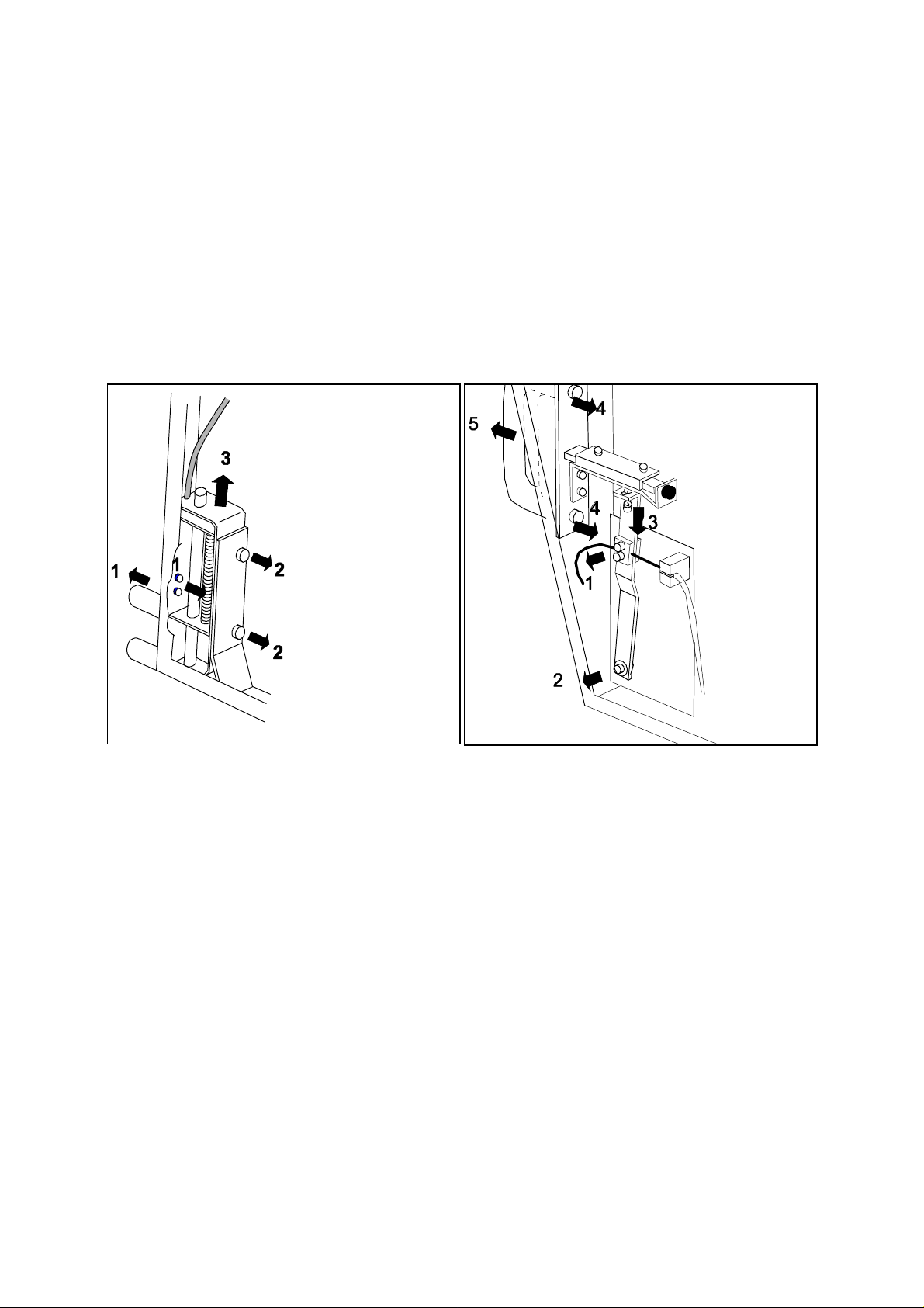
Mark the position of the rope (Fig.8) and loosen the rope.
Open all parts in mentioned sequence and remove them.
Install the tilting handle in the opposite position on the right hand side.
Change the fixed part of the handle to the opposite position.
Check the easy movement of the tilting function.
Remove the cover from the tilting housing.
Mark the position of the brake rope (Fig.9) and loosen the rope.
Open all parts in mentioned sequence and remove them.
Install the brake handle in the opposite position on the right hand side. (Position the
rounded edge correct).
Fix the rope at the marked position.
Fig. 8
Fig. 9
Check the easy movement of the brake
function.
Note: Depending on the installed Bucky-unit the grid movement inside the Bucky-unit has
to be changed too. The appropriate information’s should be withdrawn from the tech-
nical documentation of the Bucky-unit.
3.3 Installation of the spacer version V
If the optional spacer should be part of delivery it has to be installed. If it should be installed
later the column must be reinstalled and placed to the floor. The Bucky-unit has to be remounted before the spacer may be installed.
Before the column will be reinstalled the safety fixing guard at the counterbalance has to be
installed first.
0370 7221 - 14 of 26 - 06/98
Rev. 01 © 1998 Hans Pausch Röntgengerätebau Graf-Zeppelin-Str. 1 D-91056 Erlangen ALL RIGHTS RESERVED Ru

The remounting should be done in opposite sequence as the installation and is described at
section 2.
Mark the position of the brake wire rope at the fixing point and remove the wire rope.
Remove the baseplate from vertical carrier (Fig.10).
Install the spacer and fix it with 4 bolts.
Install the base plate on top of the spacer.
Fix the rope at the marked position.
Remove the safety fixing guard from the counterbalance.
Loosen all parts (Fig.11) in mentioned sequence and remove the rope-roller.
Pull the counterbalance at the rope until it is accessible.
Reinstall the rope holder (Fig.5.2.1 Pos.32).
Loosen the safety nut from the counterweight plate (Pos.35).
Put on the additional counterweight plates (5,2 Kg).
Install the safety nut and the rope holder again.
Insert the counterbalance again, secure it and install the rope-roller again.
Fig. 10
06/98 - 15of 26 - 0370 7221
Rev. 01 © 1998 Hans Pausch Röntgengerätebau Graf-Zeppelin-Str.1 D-91056 Erlangen ALL RIGHTS RESERVED Ru

4. Electrical diagrams
0370 7221 - 16 of 26 - 06/98
Rev. 01 © 1998 Hans Pausch Röntgengerätebau Graf-Zeppelin-Str. 1 D-91056 Erlangen ALL RIGHTS RESERVED Ru

5. Preventive Maintenance
5.1 Exchange of wire rope
Wire ropes have to be exchanged after 3 years of operation or if:
there are 12 or more broken wires in any 100 mm section.
or there are 3 and more broken wires in any 10 mm section.
If the check of a wire rope reveals one broken strand the customer has to be notified that
any further operation endangers the safety of patient and operator so that the unit should
not be used until the defective wire rope has been replaced.
At both versions the column must not be re-installed completely to exchange the rope.
At the version V the Bucky-unit and the base plate must be re-installed to exchange the
rope.
At the version VK the fixing point for the rope will be accessible if the Bucky-unit will be tilt
to the horizontal position and the cover has been re-installed.
Re-install the cover
Move the Bucky-unit until the tapping hole in the counterweight and the bore in the column
are congruence.
Fix the counterbalance by a M12 bolt and washer.
Lift the Bucky-unit until the rope relieves and fix the Bucky-unit in this position by a wooden
block.
Loosen the wire rope at the Bucky carrier side.
Loosen all parts (Fig.11) in mentioned sequence and remove the rope-roller. (The fixing bolt
of the rope at the counterbalance side will be accessible now.)
Loosen the rope at the counterbalance and exchange the rope.
Install the rope-roller again.
Install the rope at the carrier. ( Pay attention to washers and parts at both fixing points and
check that the rope safety part is installed correctly.
Remove the wooden block.
Remove the bolt at the counterbalance.
Check that the function is smooth. Install the covers.
Fig. 11
06/98 - 17of 26 - 0370 7221
Rev. 01 © 1998 Hans Pausch Röntgengerätebau Graf-Zeppelin-Str.1 D-91056 Erlangen ALL RIGHTS RESERVED Ru

5.2.1 Spareparts
0370 7221 - 18 of 26 - 06/98
Rev. 01 © 1998 Hans Pausch Röntgengerätebau Graf-Zeppelin-Str. 1 D-91056 Erlangen ALL RIGHTS RESERVED Ru

5.2.2 Spareparts
06/98 - 19of 26 - 0370 7221
Rev. 01 © 1998 Hans Pausch Röntgengerätebau Graf-Zeppelin-Str.1 D-91056 Erlangen ALL RIGHTS RESERVED Ru

5.2.3 Spareparts
0370 7221 - 20 of 26 - 06/98
Rev. 01 © 1998 Hans Pausch Röntgengerätebau Graf-Zeppelin-Str. 1 D-91056 Erlangen ALL RIGHTS RESERVED Ru

5.3 Spareparts List
Part names / Ordering numbers
Note:
Failed spare parts may only be replaced with original parts listed below. When or-
dering parts always indicate serial number of unit and complete number of parts.
The exchange of parts or components may only be carried out by ourself or by
qualified personnel being authorised to do so.
See also chapter: "Safety Notes".
Item Designation Order No.
1 Column weld 0370 0120
2
3 Cover 0370 0138
4 Cover 0370 0142
5 Column fastening angle 0370 0167
6 Wall fastening angle 0370 0168
7
8 Head piece weld 0370 0183
9 Rope 0370 0189
10 Rope roller complete 0370 0191
11
12 Head cover weld 0370 0210
13
14
15 Vertical carrier 0370 0300
16 Pair of roller 0370 0315
17 Roller 0370 0321
18 Brake lever complete 0370 0342a
19 Brake lever complete 0370 0342b
20
21 Roller 0370 0357
22 Sheath 0370 0367
23 Brake rope 0370 0368
24
25
26 Vertical counterweight 0370 0511
27 Glide block 0370 0512a
28 Glide block 0370 0512b
29 Counterweight 0370 0514
30
31
32 Rope holder 0370 0515
33
34 Counterweight block 0370 0520
35 Counterweight plate 0370 0528a
36 Counterweight plate 0370 0528b
37
38 Spring 0005 0103b
39
40
06/98 - 21of 26 - 0370 7221
Rev. 01 © 1998 Hans Pausch Röntgengerätebau Graf-Zeppelin-Str.1 D-91056 Erlangen ALL RIGHTS RESERVED Ru

41 Grip 0005 0192b
42 Handle 0370 0645
43 Cover cap 0370 0333
44 Cable cover 0370 1382
45 Front plate 0370 0718
46 Profile bar 0370 0746
47 Belt holder 0370 1504
48 Clamp metal 0370 1505
49 Tothbelt 0370 1514
50
51 Interface ground weld 0370 0752
52 Interface cover 0370 0765
53 Corrugated hose 0007 0024e
54
55
56
57
58 Spacer kit only to use for "V" 0370 0850
59
60 Kit "free stand Installation" 0370 0900
61 Support triangle 0370 0905a
62 Support triangle 0370 0905b
63 Thread bar 0370 0909
64 Cover weld 0370 0910
65 Top weld 0370 0920
66
67 Spiral potentiometer 0006 0598c
68 Tothbelt wheel 0370 1513
69 Potentiometer cable 0370 1516
70
71 Brake disk package 0370 1055
72 Rope curve disk 0370 1101
73 connection rope 0370 1105
74
75 Micro switch assembled 0370 1115
76 Slit cover 0370 1120
77
78 Catch complete 0359 0850
79 Switch cam cranked 0370 1083
80 Switch cam 0370 1084
81 Brake metal complete 0359 0782
82 Pull spring 0370 1232
83 Sheath 0370 1226
84 Rope 0370 1227
85 Round grip short 0370 1352
86 Handle round 0370 1378
87
88 Retaining plate "VK" 0370 1375
89 Retaining plate "V" 0370 0661
90
91 Cover cap 0370 0669
92 Pressure switch with lamp 0006 0661a
0370 7221 - 22 of 26 - 06/98
Rev. 01 © 1998 Hans Pausch Röntgengerätebau Graf-Zeppelin-Str. 1 D-91056 Erlangen ALL RIGHTS RESERVED Ru

93 Telecommunications lamp 0006 0662a
94
95
96 Patient rest 0960 0702
97
98 Patient stretching rest 0960 0710
99 Axle assembled 0960 0716
100 Rack 0960 0538
101 Retaining metal weld 0960 0725
102 Insert element 0960 0714
103
104
105 Zero degree stop cpl. 0370 1180
106
107
108 Babyx holder cpl. 0960 0755
06/98 - 23of 26 - 0370 7221
Rev. 01 © 1998 Hans Pausch Röntgengerätebau Graf-Zeppelin-Str.1 D-91056 Erlangen ALL RIGHTS RESERVED Ru

5.4 Maintenance Certificate
The maintenance according to the attached maintenance instructions has been carried
out. Any parts replaced were original spare parts as shown on the list.
Replaced parts (List item no. only)
------------------------------------------------------------------------------------
Date Name of company Signature
Replaced parts (List item no. only)
------------------------------------------------------------------------------------
Date Name of company Signature
Replaced parts (List item no. only)
------------------------------------------------------------------------------------
Date Name of company Signature
Replaced parts (List item no. only)
-----------------------------------------------------------------------------------
Date Name of company Signature
0370 7221 - 24 of 26 - 06/98
Rev. 01 © 1998 Hans Pausch Röntgengerätebau Graf-Zeppelin-Str. 1 D-91056 Erlangen ALL RIGHTS RESERVED Ru

5.5 Name Plate Location
06/98 - 25of 26 - 0370 7221
Rev. 01 © 1998 Hans Pausch Röntgengerätebau Graf-Zeppelin-Str.1 D-91056 Erlangen ALL RIGHTS RESERVED Ru

Subject to technical alterations TV/Ru
0370 7221 - 26 of 26 - 06/98
Rev. 01 © 1998 Hans Pausch Röntgengerätebau Graf-Zeppelin-Str. 1 D-91056 Erlangen ALL RIGHTS RESERVED Ru
 Loading...