

Hansol Scalable All In One, Scalable All In One ELSR103-00001, Scalable All In One ELSR722-00004 Installation Manual
Page 1
ELSR722-00004 / ELSR103-00001
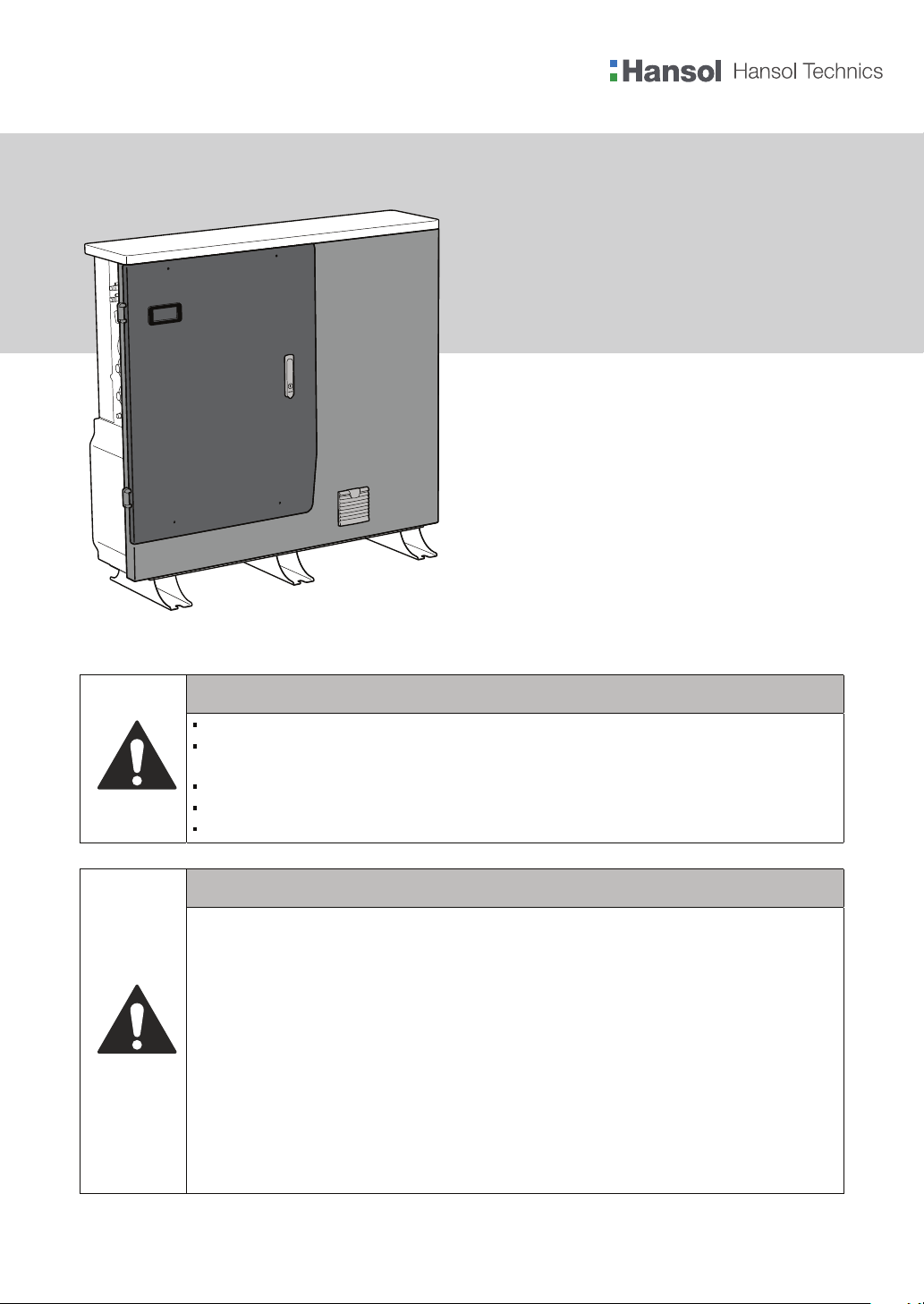
Scalable All In One
Installation Manual
ELSR722-00004: Battery Tray (ELPT362-00004) x 2
ELSR103-00001: Battery Tray (ELPT362-00004) x 3
CAUTION
Use this product only at home.
Do not operate with other components not approved by the ESS systems.
(Connecting other products in parallel to Hansol Technics’s products may result in abnormal operation.)
The internet connection is required to use all functions of the ESS system.
If you have a problem, please contact the installer.
The Specications of the product may be modied without prior notice to improve product quality.
CAUTION
Read the manual and all other available information.1.
2.
Attend Hansol installation training course/s. This course/s is recommended before the distributor
Provides an ESS.
3.
Register as a Hansol installer.
4.
Be compliant with CEC accreditation requirements for grid connect systems with batteries, which
currently requires o-grid installation accreditation.
5.
Visit the installation site prior to quoting.
6.
Check that the switchboard has room, or is suitable for, additional connection/s (e.g. external meter for
ESS 3.6 model).
7.
Be aware of Dangerous Goods Class 9 regulations for transport, storage and handling of lithium
batteries.
Be aware of Building Code regulations for battery installations.
8.
Read the manual again.
9.
Ensure you have the latest version of the installation manual, which can be downloaded from your
10.
distributor’s website.
Australia (Eng.) 11/2016. Rev1.0
Page 2

Table of Contents
Table of Contents
Table of Contents ............................................................................................................... i
Table of Tables .................................................................................................................. iv
Table of Figures ................................................................................................................. v
1. About this Manual ......................................................................................................... 1
1.1 Valid Range .................................................................................................................................................... 1
1.2 Target Group .................................................................................................................................................. 1
1.3 Manual Storage ............................................................................................................................................ 1
1.4 Symbols Used ................................................................................................................................................ 1
2. Safety .............................................................................................................................. 4
2.1 Intended Use ................................................................................................................................................. 4
2.2 Safety Precautions ....................................................................................................................................... 5
2.3 Product Overview ........................................................................................................................................ 6
2.3.1 Basic Specications ....................................................................................................................... 7
2.3.2 Grounding the PV Inverter ......................................................................................................... 7
2.3.3 Fail-safe actions upon power failure ....................................................................................... 8
3. Package Removal and Inspection ................................................................................ 9
3.1 Package Removal and Tray Assembly ................................................................................................... 9
3.1.1 Removing the Enclosure Package ........................................................................................... 9
3.1.2 Removing the Battery Tray Package ..................................................................................... 10
3.1.3 Checking Components on the Packing List ....................................................................... 11
3.1.4 Assembling the Battery Tray .................................................................................................... 12
3.2 Checking for damage in Delivery ........................................................................................................ 12
3.3 Identifying Hansol Scalable All in One .............................................................................................. 13
4. Installation ................................................................................................................... 16
4.1 Selection of Installation Location ........................................................................................................ 16
4.1.1 Possible locations for installation .......................................................................................... 17
4.1.2 Storing the ESS system .............................................................................................................. 17
4.1.3 Dimensions and Weight ............................................................................................................ 18
4.1.4 Ambient Conditions and Temperatures .............................................................................. 18
4.1.5 Minimum Clearance ................................................................................................................... 18
4.1.6 Position (Location Selection) ................................................................................................... 19
4.2 Mounting Instructions ............................................................................................................................. 20
5. Electrical Connections ................................................................................................. 22
5.1 The Overview of Electrical Connection .............................................................................................. 23
5.2 Opening the Side Case Cover ................................................................................................................ 28
5.3 The Overview of the Connection Area ............................................................................................... 29
5.4 Battery Installation .................................................................................................................................... 30
i
Page 3

Table of Contents
5.4.1 7.2 kWh and 10.8 kWh Battery Installation ......................................................................... 30
5.4.2 Scalable (From 7.2 kWh to 10.8 kWh) ................................................................................... 31
5.5 Closing the Side Case Cover .................................................................................................................. 34
5.6 A Method of Locking the Distribution Box (Board) ....................................................................... 36
5.6.1 AC Circuit Breaker and DC Isolator ........................................................................................ 37
5.6.2 RCD (residual current device) Leakage Circuit Breaker .................................................. 37
5.7 Grid Switch Box Connection between Grid and System ............................................................. 38
5.8 A Connecting Method of DC and AC Line ......................................................................................... 46
5.8.1 Mounting ........................................................................................................................................ 49
5.9 A connecting method of DRM connection ..................................................................................... 51
5.10 LAN Cable Connection between PC and System ........................................................................... 52
6. Comm
unication Connection ....................................................................................... 57
6.1 Internet Connection ................................................................................................................................. 57
6.1.1 Components .................................................................................................................................. 57
6.1.2 Connection Block Diagram ...................................................................................................... 57
6.1.3 Connection Method ................................................................................................................... 57
7. Entering Initial Installation Information ................................................................... 58
7.1 Information Input Administrator .......................................................................................................... 58
7.2 System Information input stage ........................................................................................................... 58
7.3 Web Page Connection .............................................................................................................................. 59
7.3.1 Web Page Connection ............................................................................................................... 59
7.3.2 Remote Monitoring .................................................................................................................... 66
7.4 PC Direct Connection and Local Setting Value ............................................................................... 70
7.4.1 PC Direct Connection Flow ...................................................................................................... 70
7.4.2 Inserting Jumper Wire ................................................................................................................ 70
7.4.3 LAN Cable Connection between PC and System ............................................................. 70
7.4.4 SIM (System Install Manager) Connection .......................................................................... 71
7.4.5 Operating test ............................................................................................................................... 73
7.4.6 Entering Setting Value ............................................................................................................... 78
8. Operation Test ............................................................................................................. 79
8.1 Starting the System ................................................................................................................................... 79
8.2 Turning o the System ............................................................................................................................. 81
8.3 Descriptions of Operation Mode .......................................................................................................... 81
8.3.1 PV-Auto Mode ............................................................................................................................... 81
8.3.2 PV-Only Mode ............................................................................................................................... 82
8.3.3 Battery-Discharge Mode ........................................................................................................... 83
8.3.4 Standby Mode .............................................................................................................................. 83
8.3.5 Grid-Charge Mode ...................................................................................................................... 84
8.3.6 Stand-Alone Mode ...................................................................................................................... 84
8.3.7 Self-Reliance Mode ..................................................................................................................... 84
8.3.8 Application Download Mode .................................................................................................. 85
ii
Page 4

Table of Contents
9. Problem Conrmation ................................................................................................ 86
9.1 General Events ............................................................................................................................................ 86
9.1.1 INVERTER General Events (Warnings) .................................................................................. 86
9.1.2 System General Events (Protection) ...................................................................................... 89
9.1.3 BMS General Events .................................................................................................................... 90
9.1.4 EMS/Communication Events ................................................................................................... 92
9.1.5 Single Fault Events ...................................................................................................................... 92
9.2 Signicant Events ....................................................................................................................................... 94
10. Maintenance ........................................................................................................... 96
10.1 Cleaning the Fan and the Cover ........................................................................................................... 96
10.2 Checking and Exchanging Various Components ........................................................................... 98
10.2.1 Fuse Check ..................................................................................................................................... 98
10.2.2 Input / Output Terminal Check ............................................................................................... 98
10.2.3 DC Link Check ............................................................................................................................... 99
10.2.4 FAN Operation Check ................................................................................................................. 99
10.3 Battery Maintenance ............................................................................................................................. 100
Checking Battery Problem .................................................................................................... 100
10.3.1
10.3.2
Battery Exchange Procedure ................................................................................................ 101
10.4 The List of Replaceable Parts .............................................................................................................. 102
10.4.1 Li-Ion Battery Tray ..................................................................................................................... 102
10.4.2 PV Connector ............................................................................................................................. 103
10.4.3 FAN ................................................................................................................................................. 103
11. Technical Specications ...................................................................................... 104
12. Disassembly .......................................................................................................... 109
12.1 Disassembly .............................................................................................................................................. 109
12.1.1 Removing Electric Connection ............................................................................................ 109
12.1.2 Disassembling the Main Body of Scalable All in One .................................................. 109
12.2 Packaging .................................................................................................................................................. 110
12.3 Storage........................................................................................................................................................ 110
12.4 Disposal ...................................................................................................................................................... 110
13. Contact .................................................................................................................. 111
Safety Precautions ........................................................................................................ 112
Additional Guidelines for Fire Fighting Safety Cautions for the Transporter ......... 115
iii
Page 5

Table of Tables
[Table 1-1: Symbol Description] ....................................................................................................................... 3
[Table 2-1: Part Description] ............................................................................................................................... 6
[Table 2-2: Basic Specications] ........................................................................................................................ 7
[Table 2-3: Maximum Outage Response Times for each System with Battery Full] ...................... 8
[Table 3-1: Component Description] ............................................................................................................ 11
[Table 4-1: Weight of All in One] ..................................................................................................................... 18
[Table 4-2: Specications for anchor bolt] .................................................................................................. 20
[Table 5-1: Component Description] ............................................................................................................ 25
[Table 5-2: Part List] ............................................................................................................................................. 27
[Table 5-3: Front Case Open Process] ........................................................................................................... 28
[Table 5-4: Front and Rear view of All in One (For 7.2 kWh system)] ................................................. 29
[Table 5-5: Circuit breaker, DC Isolator and power line specication] .............................................. 37
[Table 5-6: RCD Leakage circuit breaker description] ............................................................................. 37
[Table 5-7: Wire Standard] ................................................................................................................................ 46
[Table 5-8: DRMs Supported by the Inverter] ............................................................................................ 51
[Table 8-1: Description of Icons on indication screen] ........................................................................... 79
[Table 9-1: Inverter general events warning list] ...................................................................................... 87
[Table 9-2: System general events protection list] ................................................................................... 89
[Table 9-3: BMS general events list] ............................................................................................................... 90
[Table 9-4: EMS/communication events list].............................................................................................. 91
[Table 9-5: Single fault events list] ................................................................................................................. 92
[Table 9-6: Signicant events list] .................................................................................................................. 94
[Table 10-1: Replaceable parts list] ............................................................................................................. 101
[Table 11-1: Technical specications] ........................................................................................................ 105
Table of Tables
iv
Page 6

Table of Figures
[Figure 2-1: Connection Diagram] ................................................................................................................... 4
[Figure 2-2: Part View of Hansol All in One] ................................................................................................. 6
[Figure 2-3: Back up mode (LCD)] .................................................................................................................... 8
[Figure 3-1: Process for the enclosure package removal] ..................................................................... 10
[Figure 3-2: Process for the battery package removal] .......................................................................... 10
[Figure 3-3: Packing List] ................................................................................................................................... 11
[Figure 3-4: Process for the battery assembly (For 10.8 kWh System)] ............................................. 12
[Figure 3-5: Name Plate] .................................................................................................................................... 14
[Figure 3-6: Battery Tray Label] ....................................................................................................................... 15
[Figure 4-1: Dimension of All in One] ............................................................................................................ 18
[Figure 4-2: Minimum Clearance for All in One] ....................................................................................... 19
[Figure 4-3: Restriction for the surface gradient] ...................................................................................... 19
[Figure 4-4: Spanner for fastening anchor nuts (Minimums 4ea)] ..................................................... 20
[Figure 4-5: Anchor Bolt] ................................................................................................................................... 20
[Figure 4-6: A Flat head driver for the front cover knob (larger than 10 mm)] .............................. 21
[Figure 4-7: The Plus head driver (No.2) for the tray, the side cover, and grounding] ................ 21
[Figure 4-8: A spanner for fastening use] .................................................................................................... 21
[Figure 4-9: A fork lifter with height of 85-200 mm] ................................................................................ 21
[Figure 5-1: Electrical connections] ............................................................................................................... 23
[Figure 5-2: PV connections] ............................................................................................................................ 24
[Figure 5-3: Front Inside View] ........................................................................................................................ 26
[Figure 5-4: Rear Inside View] .......................................................................................................................... 26
[Figure 5-5: Side View] ........................................................................................................................................ 27
[Figure 5-6: Removed Side Cover View] ....................................................................................................... 30
[Figure 5-7: Battery Connection] .................................................................................................................... 30
[Figure 5-8: Battery Docking description] ................................................................................................... 31
[Figure 5-9: Unfastening screws] .................................................................................................................... 31
[Figure 5-10: Removal of the side cover] ..................................................................................................... 32
[Figure 5-11: Removal of the battery cover grade] .................................................................................. 32
[Figure 5-12: Battery tray mounting] ............................................................................................................ 33
[Figure 5-13: Side Cover Assembly process 1] ........................................................................................... 34
[Figure 5-14: Side Cover Assembly process 2] ........................................................................................... 34
[Figure 5-15: Side Cover Assembly process 3] ........................................................................................... 35
[Figure 5-16: Distribution box connection diagram] .............................................................................. 36
[Figure 5-17: Wiring Schematic of Single Phase System for Australia] ............................................. 40
[Figure 5-18: Components of Grid Switch Box] ......................................................................................... 40
[Figure 5-19: Assembling the Cable Gland] ................................................................................................ 41
[Figure 5-20: Wiring Diagram] ......................................................................................................................... 41
[Figure 5-21: Assembling the Wires] ............................................................................................................. 42
[Figure 5-22: Assembling the Sealing nuts] ................................................................................................ 42
[Figure 5-23: Final assembly] ........................................................................................................................... 43
[Figure 5-24: Assembling the Upper Part] ................................................................................................... 43
[Figure 5-25: Assembling the Rubber Seal] ................................................................................................ 44
[Figure 5-26: Assembling the Knob] .............................................................................................................. 44
[Figure 5-27: Final Assembly] ........................................................................................................................... 45
[Figure 5-28: PV connector (Female) and PV line (Male)] ...................................................................... 46
[Figure 5-29: Load Connector (Male) and Grid Connector (Female)] ................................................ 46
[Figure 5-30: Connection of system for oating solar array, load and grid] ................................... 47
[Figure 5-31: PV connector connection (MC4 connector connection)] ........................................... 47
Table of Figures
v
Page 7

Table of Figures
[Figure 5-32: L and N AC line connection method] ................................................................................. 48
[Figure 5-33: Optional Actions] ....................................................................................................................... 50
[Figure 5-34: Structure of the cable for RJ45 sleeve housing] ............................................................. 51
[Figure 5-35: RJ45 cable clip and the groove of RJ45 sleeve housing] ............................................. 51
[Figure 5-36: Assembling RJ45 LAN cable] ................................................................................................. 52
[Figure 5-37: Fastening RJ45 LAN cable in RJ45 sleeve housing] ....................................................... 52
[Figure 5-38: Assembling the waterproof cap set] .................................................................................. 52
[Figure 5-39: Putting the sealing cap into RJ45 sleeve housing] ........................................................ 53
[Figure 5-40: Assembling the sealing nut to RJ45 sleeve housing] ................................................... 53
[Figure 5-41: Assembled RJ45 sleeve housing cable] ............................................................................. 53
[Figure 5-42: Opening the cap of RJ45 LAN socket] ................................................................................ 54
[Figure 5-43: Position of RJ45 LAN port] ...................................................................................................... 54
[Figure 5-44: Inserting the assembled cable] ............................................................................................. 54
[Figure 5-45: Upper and lower locking grooves] ...................................................................................... 55
[Figure 6-1: Internet Connection]................................................................................................................... 56
[Figure 7-1: Main page] ...................................................................................................................................... 58
[Figure 7-2: Installer in page] ........................................................................................................................... 59
[Figure 7-3: Product Information Entry Screen in Step 1] ..................................................................... 60
[Figure 7-4: Address Entry in Step 2] ............................................................................................................. 61
[Figure 7-5: Product Setup Information Details Entry in Step 3]......................................................... 62
[Figure 7-6: Energy Rate Information Entry in Step 4] ............................................................................ 63
[Figure 7-7: Installation Completion Screen] ............................................................................................. 64
[Figure 7-8: Remote Monitoring Screen] ..................................................................................................... 65
[Figure 7-9: Selection of Product Serial No. to Test] ................................................................................ 65
[Figure 7-10: Selection of Detailed Product Information] ..................................................................... 66
[Figure 7-11: Operation checkup for energy meter page] .................................................................... 66
[Figure 7-12: ESS Operation Test Page] ........................................................................................................ 67
[Figure 7-13: Jumper] ......................................................................................................................................... 69
[Figure 7-14: TCP/IP setting] ............................................................................................................................ 70
[Figure 7-15: Initial setup page] ...................................................................................................................... 71
[Figure 7-16: Operating Test Screen] ............................................................................................................ 72
[Figure 7-17: PV-Output Test Screen] ........................................................................................................... 73
[Figure 7-18: Grid-Charge Test Screen] ........................................................................................................ 74
[Figure 7-19: Battery-Discharge Test Screen] ............................................................................................. 75
[Figure 7-20: Auto-Weak/Strong Test Screen] ........................................................................................... 76
[Figure 8-1: Initial indication screen on power on] .................................................................................. 78
[Figure 8-2: Standby state indication screen before the EMS command] ....................................... 79
[Figure 8-3: PV generation, Battery charge, Load use, sell remaining amount] ............................ 80
[Figure 8-4: PV generation, Battery discharge, Load use, buy shortage amount] ........................ 80
[Figure 8-5: PV generation, Battery standby, Load use, sell remaining amount] ......................... 81
[Figure 8-6: PV generation, Sell remaining amount] ............................................................................... 81
[Figure 8-7: PV generation, Buy shortage amount] ................................................................................. 81
[Figure 8-8: Battery discharge, Load use] .................................................................................................... 82
[Figure 8-9: Battery discharge, Load use, Buy shortage amount] ...................................................... 82
[Figure 8-10: Indication screen on Standby Mode, Buy shortage amount] .................................... 82
[Figure 8-11: Indication screen on Grid charge Mode] ........................................................................... 83
[Figure 8-12: Indication screen on stand-alone mode] .......................................................................... 83
[Figure 8-13: Indication screen on Self-Reliance mode, Battery to LOAD discharge] ................. 83
[Figure 8-14: Indication screen on Self-Reliance mode, PV to BATTERY charge (LOW SOC)] ... 84
[Figure 8-15: Indication screen on Application Download Mode] ..................................................... 84
[Figure 10-1: PV MC4 connector] .................................................................................................................... 95
[Figure 10-2: Upper cover removal] .............................................................................................................. 96
[Figure 10-3: Fan removal] ................................................................................................................................ 96
vi
Page 8

Table of Figures
[Figure 10-4: Li-Ion Battery tray (manufactured by SAMSUNG SDI)] .............................................. 101
[Figure 10-5: PV Connector (MC4)] ............................................................................................................. 102
[Figure 11-1: Derating Curve] ....................................................................................................................... 106
[Figure 11-2: Power eciency curve of System] .................................................................................... 106
[Figure 11-3: Power eciency curve of PV Generation] ..................................................................... 107
vii
Page 9
1. About this Manual
1.1 Valid Range
This is the installation manual for the Scalable (7.2 kWh/10.8 kWh) All in One system. Please
read this installation and user manual carefully before installing and operating the scalable
all in one system.
It contains important safety instructions. The warranty will be void if you fail to follow the
instructions in this manual.
1.2 Target Group
This installation manual applies only to the Hansol Scalable All in One.
1.3 Manual Storage
The user manual and installation manual can be downloaded from the product download
section at
changed for improvement without notice.
“https://myess.hansoltechnics.com”. The specications of the product can be
1. About this Manual
Also, the software can be updated automatically without notice over the Internet.
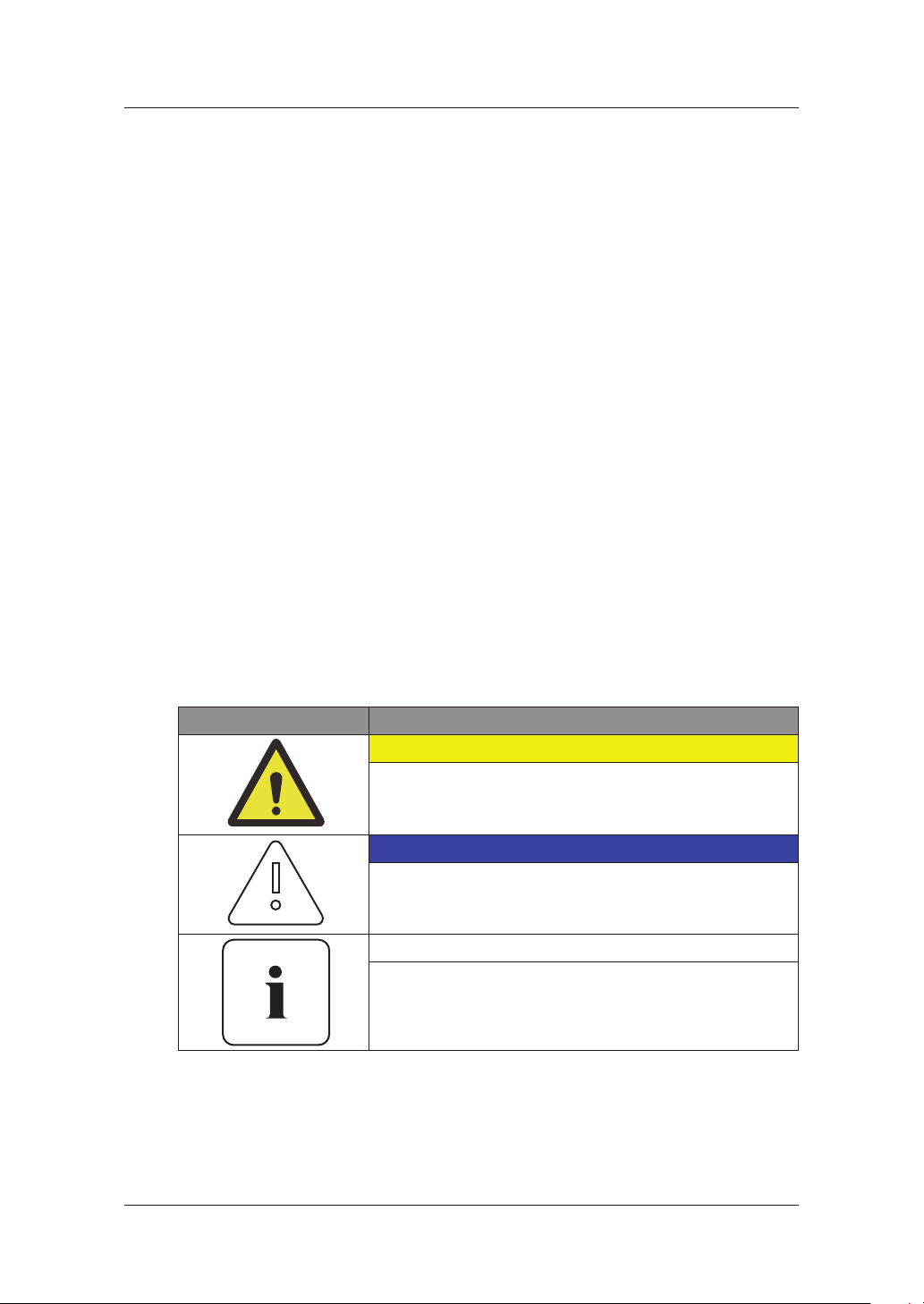
1.4 Symbols Used
Symbols Meaning
CAUTION
This symbol indicates a hazardous situation which could
result in a light injury, if not avoided.
NOTICE
This symbol indicates a hazardous situation which could
result in damage to the property, if not avoided.
Information
This symbol indicates valuable tips for optimum installation
and operation of the product.
1
Page 10
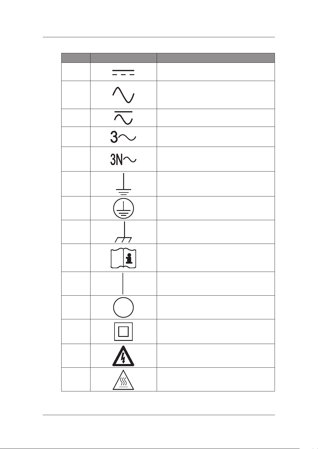
Number Symbol Description
About this Manual
1
2
3
4
5
6
7
8
Direct current
Alternating current
Both direct and alternating current
Three-phase alternating current
Three-phase alternating current with neutral
conductor
Earth terminal
Protective conductor terminal
Frame or chassis terminal
9
10
11
12
13
14
Refer to the operating instructions
On (supply)
O (supply)
Equipment protected throughout by double
insulation or reinforced insulation
Caution: Risk of Electric Shock
Caution: Hot Surface
2
Page 11
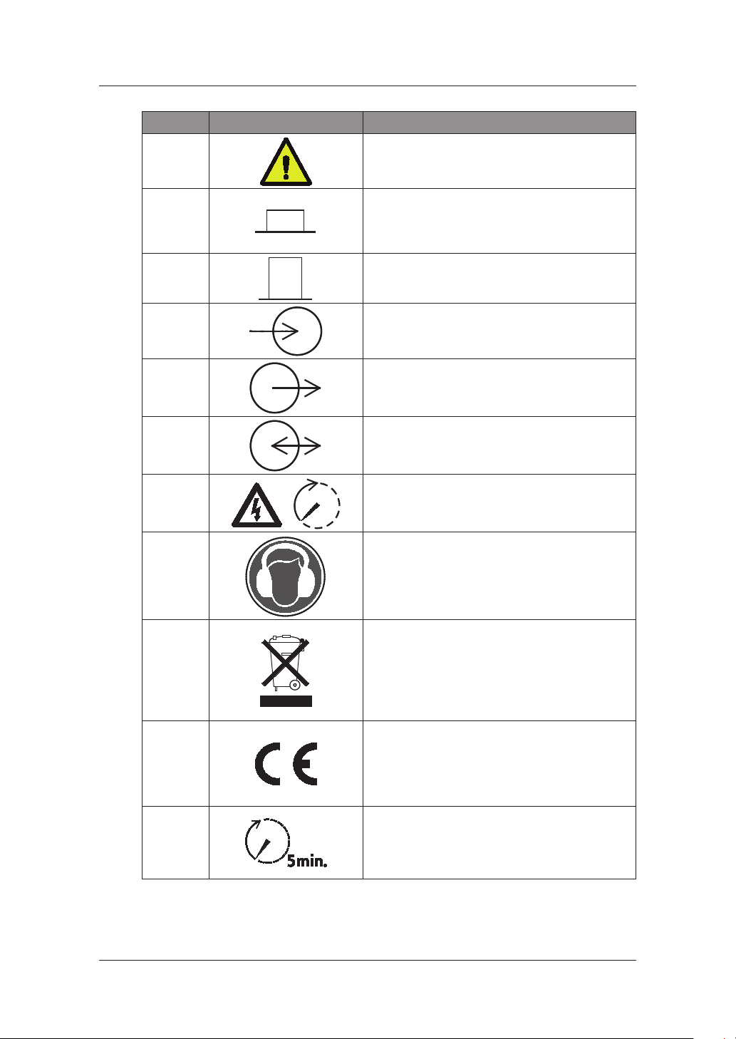
Number Symbol Description
About this Manual
15
16
17
18
19
20
21
22
Caution: Risk of Danger
In position of a bi-stable push control
Out position of a bi-stable push control
Input terminal or rating
Output terminal or rating
Bidirectional terminal rating
Caution: Risk of Electric Shock and Energy
Storage Timed Discharge
Caution: Risk of Hearing Damage and Wear
Hearing Protection Wear hearing protection
23
24
25
Do not dispose of the inverter with household
wastes.
For further information on disposal, refer to the
[Table 1-1: Symbol Description]
installation manual provided.
The CE Indication:
The relevant equipment complies with the
requirements in the EC guidelines.
Caution: Risk of Electric Shock and wait at least
5 min after power turn o when opening the
product.
3
Page 12
2. Safety
2.1 Intended Use
NOTICE
The Scalable All in One system is intended for residential use only.
The Scalable All in One system should not be used for commercial or
building.
The Scalable All in One system is designed for residential use. It is a single-phase, gridconnected system of solar energy sources and Li-Ion Battery energy storage.
The Scalable All in One system uses solar energy power connected to the input/output
terminal installed on the side of the device in order to:
1) charge the Li-Ion battery energy storage,
2) provide a supply to the household load, and
3) convert direct current (DC) e
discharge as household single-phase load or electric system.
This device should not be used for any purpose other than the purpose described in this
installation manual. Any substitute use of this device, random change in any of its parts, and
use of components other than sold or recommended by Hansol Technics will nullify the
product’s guarantee. For example, Hansol Li-Ion battery energy storage should
replaced by other manufacturer’s battery storages. For further information on proper use of
this device, contact the Hansol Technics Service line or visit at“www.hansoltechnics.com”
lectricity of the battery to alternating current (AC) to
2. Safety
not be
[Figure 2-1: Connection Diagram]
4
Page 13
2.2 Safety Precautions
CAUTION
High voltages in power conditioning circuits. Lethal hazard of electric shock
or serious burns.
All work on the PV modules, inverters, converters, and battery systems must
be carried out by qualied personnel only.
Wear rubber gloves and protective clothing (protective glasses and boots)
when working on high voltage/high current systems such as INVERTER and
battery systems.
CAUTION
Li-Ion battery energy storage system (ESS) inside. When assembling the
system, do not intentionally short the positive (+) and negative (-) terminals
with metallic object.
All work on the ESS and electrical connections must be carried out by
qualied personnel only. The ESS within Scalable All in One provides a safe
source of electrical energy when operated as intended and as designed.
A potentially hazardous circumstance such as excessive heat o
mist may occur due to improper operating conditions, damage, misuse
and/or abuse. The following safety precautions and the warning messages
described in this section must be observed. If any of the following
precautions are not fully understood, or if you have any questions, contact
Customer Support for guidance (see chapter 13).
The safety section may not include all regulations for your locale; personnel
working with Scalable All in One mu
local regulations as well as the industry standards regarding this product.
2. Safety
r electrolyte
st review applicable federal, state and
CAUTION
This product is intended to be used for PV source inputs and residential
home grids (AC 230V). If not used as intended, the protection provided by
the equipment may be impaired.
CAUTION
This device is designed appropriate for two-PV string structure. Therefore, the
PV string 1 and PV string 2 must be connected to PV input 1 and PV input 2,
respectively.
Do not split one PV string output for connecting it into the PV input terminal
1 and input terminal 2.
5
Page 14
2.3 Product Overview
The All in One system includes the PV inverter, battery charger/discharger, Li-Ion battery, and
EMS.
The basic operating modes consist of PV generation mode, PV generation +
charge/discharge mode. The operation mode of this product is automatically determined by
the EMS algorithm.
10
2. Safety
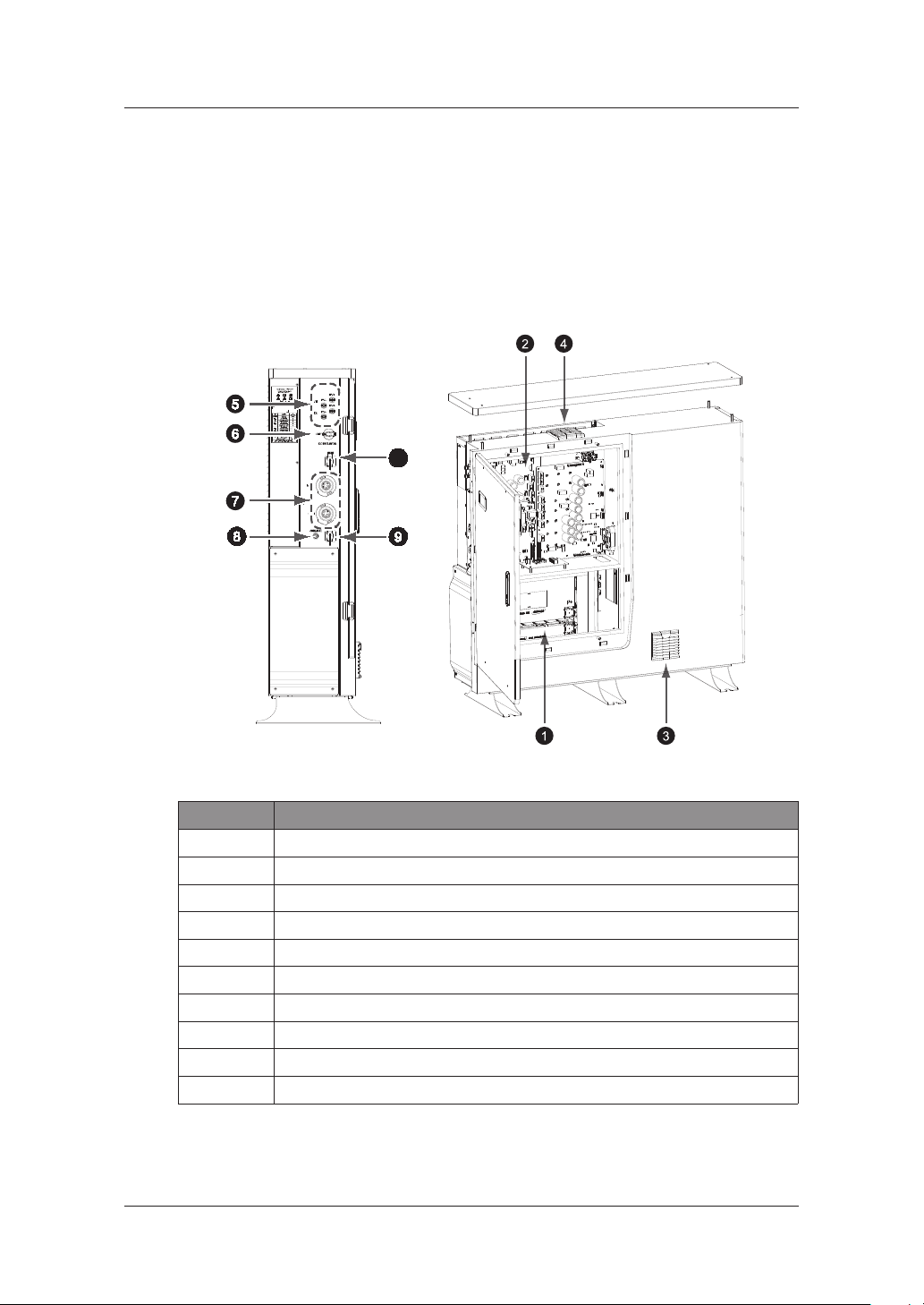
[Figure 2-2: Part View of Hansol All in One]
No. Description
1 Lithium Ion battery
2 INVERTER & Converter (PV inverter and battery charger / discharger)
3 Air Filter1 (Bottom)
4 Air Filter2 and FAN (Top)
5 Input terminal (MC4-2set)
6 DC isolator
7 Grid and Load connector (RST50i5S connector)
8 Service Connecter for Installation
9 Communication (LAN)
10 DRM Connection (LAN)
[Table 2-1: Part Description]
6
Page 15
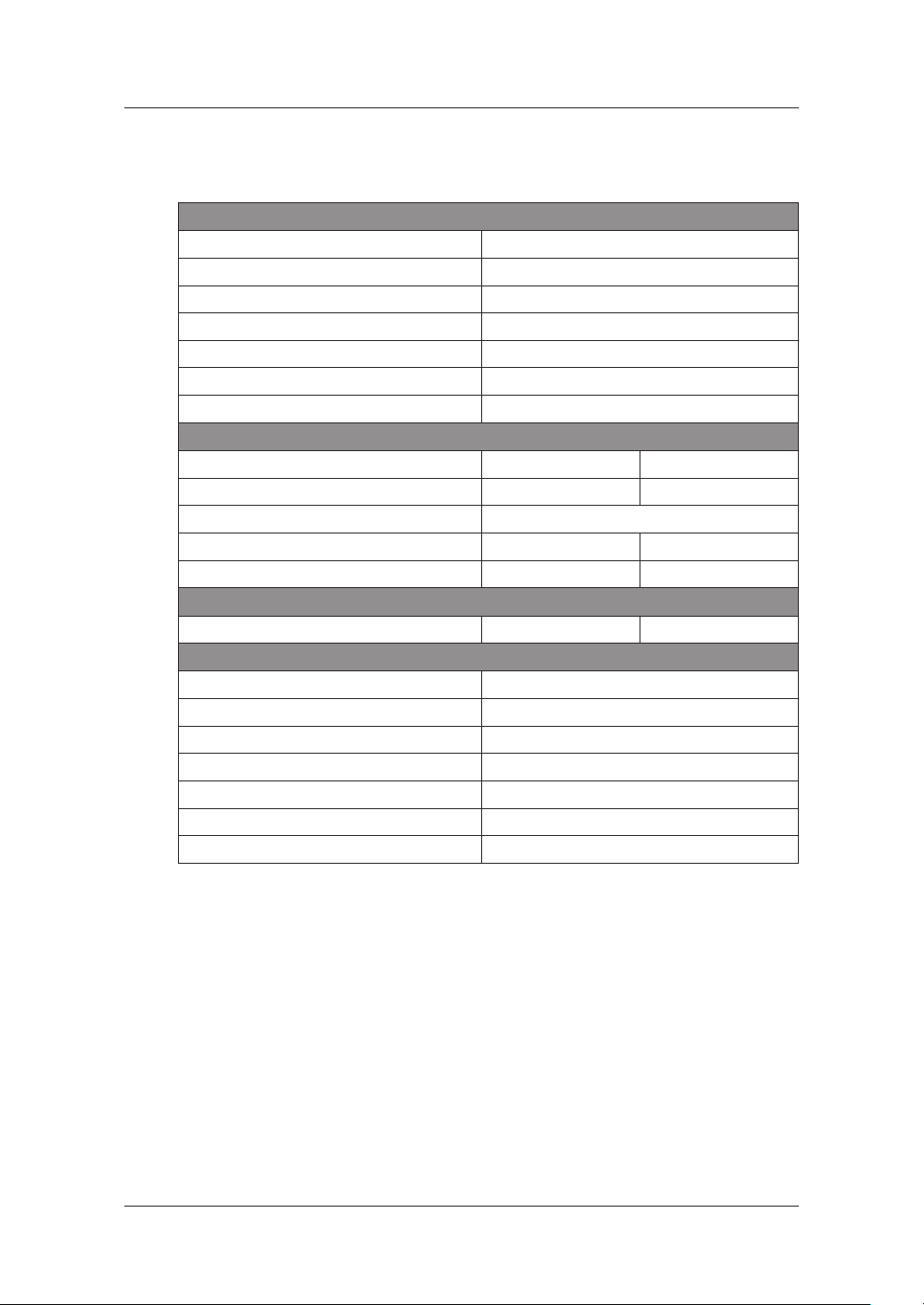
2.3.1 Basic Specications
Max. input total power 6.6 kWp
Max. input power per string 3.3 kWp
Max. input voltage 550 V
Min. input voltage/Initial input voltage 125 V/150 V
MPPT voltage range 125 V~500 V
Max. input current per string 15 A
Number of independent MPP trackers 2
System model No. ELSR722-00004 ELSR103-00001 (*)
Battery rated capacity 7.2 kWh 10.8 kWh
DOD (Depth of Discharge) 90 % (6000cycles, 5 ~ 95 %),
Battery voltage range/nominal voltage 96 ~ 132 V / 120 V 145 ~ 198 V / 180 V
Battery Max. current 46 A 38 A
Rated power 4.0 kW 4.98 kW
Grid Connection Data (AC)
Rated power 4.98 kW
Max. apparent AC power 4.98 kVA
Max. output current 22 A
Max. input AC power 8 kW
Max. allowed current for fuse protection 43 A
Nominal AC voltage/range 230 V/200 V~270 V
Rated power frequency 50 Hz
2. Safety
PV Generator Data (DC)
Battery Data (DC)
Battery DC/DC Converter Data
(*):2 battery trays for 7.2 kWh; 3 battery trays for 10.8 kWh
[Table 2-2: Basic Specications]
2.3.2 Grounding the PV Inverter
The PV inverter complies with the local requirements for grounding the PV inverter.
Hansol Technics recommends connecting and grounding the PV inverter
electricity conducting surfaces in such a way that there is continuous conduction in order to
achieve maximum protection for systems and persons. And the PV inverter
and DC (-) pole are not permitted to be grounded.
’s frame and other
’s DC (+) pole
7
Page 16

2.3.3 Fail-safe actions upon power failure
When a system outage occurs, the utility pole in the following gure disappears and it
switches to the backup mode after 20 seconds to supply power. With 7.2 kWh, the supplied
power is a maximum of 4 kW and with 10.8 kWh, a maximum of 4.98 kW.
The back mode is canceled in 5 minutes after return to normal operation.
The utility pole appears when power is supplied to the system. Upon system outage, it
disappears. Upon PV generation, the sun mark appears.
[Figure 2-3: Back up mode (LCD)]
Under DOD 90% and 95% of battery to loads, the 7.2 kWh system can operate for approx. 92
minutes and the 10.8 kWh system for approx. 110 minutes.
2. Safety
System Battery capacity Battery energy Load Hour Min
7.2 kWh 7.2 kWh 6.48 kWh 4 kW 1.5 92.3
10.8 kWh 10.8 kWh 9.72 kWh 4.98 kW 1.8 110.8
[Table 2-3: Maximum Outage Response Times for each System with Battery Full]
NOTICE
The outage response time may vary depending on the battery
capacity and loads.
8
Page 17
3. Package Removal and Inspection
3. Package Removal and Inspection
CAUTION
Included in this box are a battery and printed circuit board, and the entire
weight amounts to 105 kg. Therefore, special care must be taken in handling.
Make sure to have at least two persons deliver with something like trolleys
and remove the package.
3.1 Package Removal and Tray Assembly
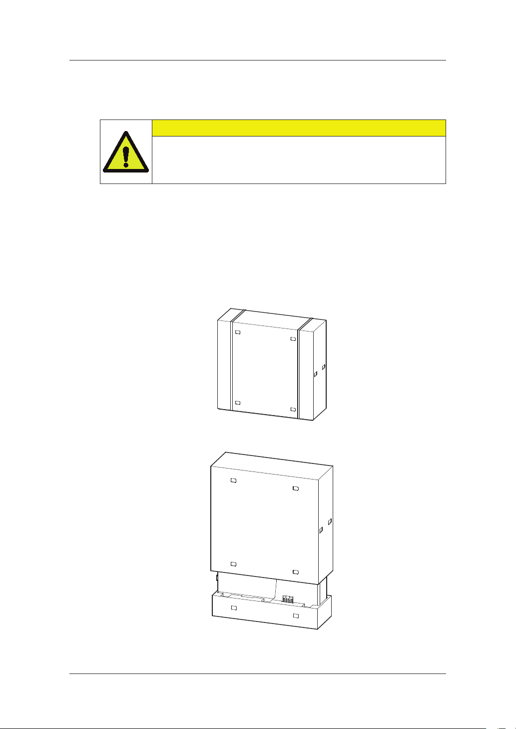
3.1.1 Removing the Enclosure Package
As shown in the gure in this section, remove the package components from the enclosure
in the following order.
1. Place the system on the installation location.
2. Open the upper part of the system case.
3. Remove top side of the cover in the front of the product.
9
Page 18
4. Open the side support on the bottom.
3. Package Removal and Inspection
[Figure 3-1: Process for the enclosure package removal]
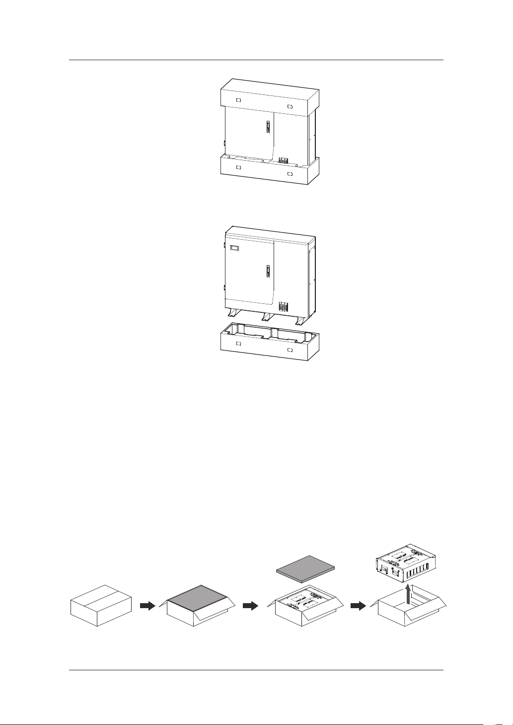
3.1.2 Removing the Battery Tray Package
As shown in the [Figure 3-2], remove the package for the battery tray.
1. Open the box cover of the product.
2. Remove the buers with a straight pull.
3. Take out the battery tray by grabbing the handle and pulling it up.
Note: The tray weighs approximately 45 kg, so make sure to have at least two persons
lift it.
[Figure 3-2: Process for the battery package removal]
10
Page 19

3. Package Removal and Inspection
3.1.3 Checking Components on the Packing List
Once the product has been delivered, refer to the gure [Figure 3-3] and [Table 3-1], identify
the entire components included in the package and the correct number of the quantity
listed in the table.
Packing List
[Figure 3-3: Packing List]
Object Part Name Code No. Quantity
A INVERTER ASSY SJ94-00146A or SJ94-00147A 1
B TRAY ASSY ELPT362-00004 2 or 3(*)
C 1. SCREW(M4xL8)
2. LAN Connector
3. GRID Connector
4. LOAD Connector
5. Service Connector
6. DOOR KEY
7. Grid Switch Box
D Installation Quick Guide
Manual
(*):2 battery trays for 7.2 kWh system; 3 battery trays for 10.8 kWh system
[Table 3-1: Component Description]
6001-002698
VS-08-T-H-RJ45/IP67
97.051.4253.1
97.052.4253.1
A366-CP-T0651
3406-001136
SJ68-02142A 1
12
2
1
1
1
2
1
11
Page 20

3. Package Removal and Inspection
3.1.4 Assembling the Battery Tray
The [Figure 3-4] shows the assembly process for the battery tray. Refer to Clause 5.4 and
assemble the battery tray as described in it.
[Figure 3-4: Process for the battery assembly (For 10.8 kWh System)]
3.2 Checking for damage in Delivery
When opening the box that contains Hansol Scalable All in One system in it, check for any
possible damage caused in transit and ensure the correct number of the components
therein. If there is a scratch on the enclosure, contact your local dealer for inspection and
service.
12
Page 21

3. Package Removal and Inspection
3.3 Identifying Hansol Scalable All in One
Attached on the enclosure of this product is the Type Label where the identity of this
product is described. For safe usage, make sure that the following product information is
indicated on the Type Label.
■ Product Name
■ Device Type (Model)
■ Serial Number (Serial No.)
■ Device-specic characteristics
■ Certication Lists
■ Warnings and Notication
The model No. of All in One system is dened
■ ELSR722-00004
• ELSR: Residential application
• 72: Battery capacity (x0.1 kWh, Less than 10 kWh)
• 2: Battery capacity group
• 00004: product line number
■ ELSR103-00001
• ELSR: Residential application
• 10: Battery capacity (x1 kWh, More than 10 kWh)
• 3: Battery capacity group
• 00001: product line number
The model No. of INVERTER (power conditioning system) is dened as below.
■ SJ94-00146A
• SJ: battery for ESS
• 94: Ass’y
• 00146: product number
• A: National
Code (Australia)
as below.
The Type Label is shown in the [Figure 3-5].
13
Page 22

3. Package Removal and Inspection
IEC62109-1/-2, AS62040.1.1, AS4777.2:2015, IEC62619,
IEC60730-1 Annex H, IEC61000-6-2/-3, IEC61727, IEC62116
[Figure 3-5: Name Plate]
14
Page 23

The product serial number is dened as below
■ AR00500108Z11510300001C
• AR: Residential Type
• 0050: Output power of inverter (x0.1 kW) *
• 0108: Capacity of battery (x0.1 kWh )
• Z1: Factory Line
• 151030: Production date (YY-year, M-month, DD-day)
• 0001: Production order per day (001 ~ 999)
• C: National Code (Australia)
(* It was rounded o. (e.g. 4.98 → 5.0))
The Battery Tray Label is shown in the [Figure 3-6].
The number of Battery Tray is normally not mat
It is nally coupled when installing
ched inverter’s one.
3. Package Removal and Inspection
[Figure 3-6: Battery Tray Label]
The battery tray serial number is dened as below
■ ET361A14709000X
• ET: Tray type
• 36: Capacity of tray (under x0.1 kWh)
• 1A: Factory Line
• 14709: Production date (YY-year, M-month, DD-day)
• 0001: Production order per day (0001 ~ 9999)
• X: Grade of Cell
15
Page 24

4. Installation
4.1 Selection of Installation Location
CAUTION
Danger to life due to re or explosion!
Danger to life due to high voltages!
Despite careful construction, a re can occur with electrical devices.
Do not install the Scalable All in One on the following locations:
On ammable construction materials;
In potentially explosive areas; and
In areas where highly ammable materials are stored!
CAUTION
Li-Ion battery energy storage is equipped within Scalable All in One.
The ESS within Scalable All in One provides a safe source of electrical
energy when operated as intended and as designed.
A potentially hazardous circumstance such as excessive heat or
electrolyte mist may occur due to improper operating conditions,
damage, misuse and/or abuse. The following safety precautions and
the warning messages described in this section must be obse
If any of the following precautions are not fully understood, or if you
have any questions, contact Customer Support for guidance. The
Safety Section may not include all regulations for your locale;
Personnel working with 7.2/10.8 kWh All in One must review
applicable federal, state and local regulations as well as the industry
standards regarding this product.
4. Installation
rved.
CAUTION
All work on the ESS and electrical connections must be carried out by
qualied personnel only.
16
Page 25

4.1.1 Possible locations for installation
4. Installation
Selecting an optimal installation location for the ESS is required for operation safety,
eciency and life of the product.
1. This IP54 product is recommended to be installed indoor. If it is required to be installed
outdoor, the place must have a roof to avoid direct sunlight, rain and snow.
2. Install the product in a well ventilated and clean area with no dust or insects.
(e.g. stockyards and carpets are not allowed).
3. Do not install the produc
4. Do not install the product where a re or explosion might occur.
5. Install the product in a place that is not exposed to corrosive gases (e.g. ammonia, acid,
salinity content, etc.).
6. Install the product in a place where children cannot reach.
7. Install the product considering the noise level because noise is generated during
operation, which may cause discomfort. (e.g. near a b
8. The oor must be hard so that it can withstand the weight and vibration of the product.
(e.g. concrete structure)
9. The oor must not be sloped or recessed where a pool of water may form. If this is an
issue, adjust the height of the oor to be at a higher point.
t in an area prone to oods or a high humidity area.
edroom)
10. The oor surface must be xed with anchors.
11. Do not install the product on ammable material. Flammable materials must not be
placed within a specic distance.
12. Objects must
13. After connecting all the cables, make sure that they are rmly inserted.
not be stacked on top of the product.
4.1.2 Storing the ESS system
1. The product must not be tilted when being moved. It must be lifted vertically.
2. The product must not fall from a height of 10 cm or more.
3. Make sure the product does not get wet in the rain or snow.
4. Do not stack the products on top of each other.
17
Page 26

4.1.3 Dimensions and Weight
Once the 7.2/10.8 kWh All in One system has been assembled, its dimension is 1140 x 1200 x
280 mm, and its weight is approximately from 194 kg (7.2 kWh) to 239kg (10.8 kWh).
The [Figure 4-1] and [Table 4-1] show the outer dimensions and the weight of the device
after assembly, respectively.
4. Installation
[Figure 4-1: Dimension of All in One]
System Battery Inverter ( Include case) Total
7.2 kWh 90 kg 104 kg 194 kg
10.8 kWh 135 kg 104 kg 239 kg
[Table 4-1: Weight of All in One]
4.1.4 Ambient Conditions and Temperatures
Identify a proper installation location to install and remove the device easily at any time.
This device must be located within reach distance.
The ambient temperature of the installation location will range from -10°C to +40°C.
4.1.5 Minimum Clearance
This device is required to maintain a minimum clearance distance for the safe installation of
the product. Refer to the
from the wall, 1 m in the front of the device, 1 m on both sides, and 0.3 m on top.
[Figure 4-2] to secure enough space and keep a distance of 0.1 m
18
Page 27

[Figure 4-2: Minimum Clearance for All in One]
4.1.6 Position (Location Selection)
As shown in the [Figure 4-3], install the device on a at surface. (Front, back, left, right
gradient within ±0.5°)
To allow for natural ventilation, the side of the system must be kept away from the wall
about 0.3m at least. Make sure not to have foreign substances and objects stuck in the
blowing fan, ventilation entrance and exit sides.
4. Installation
°5.0 ~ °0
°5.0 ~ °0
19
[Figure 4-3: Restrict
°5.0 ~ °0
ion for the surface gradient]
0° °5.0 ~
Page 28

4.2 Mounting Instructions
[Figure 4-4: Spanner for fastening anchor nuts (Minimums 4ea)]
4. Installation
[Figure 4-5: Anchor Bolt]
Screw
name
1/2 (M12) 100 60 17 50 17 55 (mm) 3,200 (kgf) 3,400 (kgf )
L S D L1
[Table 4-2: Specications for anchor bolt]
Drill
Used
Drill
depth
(Min.)
Tensile
capacity
(Max.)
Shear
Capacity
(Max.)
20
Page 29

1. Select the drill proper for specications for drilling specications.
2. Remove the dust from the hole, then separate the nut and the washer to insert both the
bolt and the cap.
3. Set the product in place, assemble the washer and the nut to the bolt, and then use the
spanner to fasten the nut (7 Nm).
Required tools for installation
[Figure 4-6: A Flat head driver for the front cover knob (larger than 10 mm)]
[Figure 4-7: The Plus head driver (No.2) for the tray, the side cover, and grounding]
4. Installation
[Figure 4-8: A spanner for fastening use]
[Figure 4-9: A fork lifter with height of 85-200 mm]
21
Page 30

5. Electrical Connections
NOTICE
The All in One system can be damaged by static discharge.
Before you touch a component inside the All in One, ground yourself by
touching PE or a grounded object
CAUTION
When handling with the Li-Ion Battery Tray for the All in One, you must
wear the following personal protective equipment:
High voltage rated rubber gloves
Safety goggles or other protective eye equipment
40-minute standby period of time to complete discharging in the system
before testing electrical parts inside the system!
Follow the guidelines below when handling the Li-Ion Battery Tray.
Do not intentionally short circuit the positive (+) and negative (-) terminals
with a metallic object.
Do not remove the cap on the terminals. If the cap is removed, avoid
contact between the metals and the battery terminals. Do not damage the
screw thread.
Do not use seriously scarred or deformed battery. Dispose immediately
according to proper regulations.
Do not damage sheath of cable and connectors.
5. Electrical Connections
22
Page 31

5. Electrical Connections
5.1 The Overview of Electrical Connection
The Scalable All in One has two solar energy inputs (PV1, PV2). 3.3 kW (per string) is the
maximum output for each PV input. The Grid of All in One is connected to the Grid. The Load
of All in One is connected to the Home Load. Between the Home Load and the Grid, the
Digital Energy Meter is placed for power metering. The AC circuit breaker and DC Isolator in
the distribution box are installed between the All in O
ne for safety reasons.
[Figure 5-1: Electrical connections]
As shown in the [Figure 5-2], the Scalable All in One uses the two independent channels of
the PV Input ({PV1+, PV1-}, {PV2+, PV2-}). They are used independently for running the
maximum power from the sources of PV1 and PV2. Two channels are recommended for
independent use for the two PV Inputs. Make sure not to connect one PV string in parallel
with the two independent PV inputs (PV1, PV2). (Refer to Scalab
input connection in the [Figure 5-2]).
A PV string must not be commonly connected to the two input terminals of the All in One
system. That is, make sure not to connect the split wiring from one PV string output with the
two independent PV inputs (PV1+, PV1- and PV2+, PV2-). (Refer to the PV String connection
method in the [Figure 5-2]).
When want connect the two PV input with one PV Module, should be carried out by
qualied perso
nnel only.
le All in One Solar energy
※PV modules shall have an IEC61730 Application Class A rating or equivalent.
23
Page 32

[Figure 5-2: PV connections]
5. Electrical Connections
24
Page 33

5. Electrical Connections
As shown in the [Table 5-1], the input / output power cables correspond to the AC/ DC input
/ output specications for this system.
Recommended cables for the Scalable All in One
Area Insulation Color code
Grid/Load (L, N) 6~16 mm2 600 V or more Black
PE 6~16 mm2 600 V or more Green with yellow lines
PV (+), (-) 6 mm2 700V or more Black
Object Part List Type
D DC Isolator INVERTER
R Battery Relay INVERTER
F Air Filter1 (Bottom) INVERTER
DC DC Board (PN. SJ92-01490A) INVERTER
AC AC Board (PN. SJ92-01489A) INVERTER
SW SW Board (PN. SJ92-01491A) INVERTER
EMS EMS Board (PN. SJ92-01424x) INVERTER
A AC reactor INVERTER
P1 PV1 reactor INVERTER
P2 PV2 reactor INVERTER
B1 BDC1 reactor INVERTER
B2 BDC2 reactor INVERTER
H Heat sink INVERTER
C1 DC reactor case INVERTER
C2 AC reactor case INVERTER
BT Battery Tray top view BATTERY
AC_SUB AC sub board INVERTER
TR Transformer INVERTER
[Table 5-1: Component Description]
25
Page 34

5. Electrical Connections
The [Figure 5-3] shows the overall drawing of the scalable system. Please refer to the gure
of the drawing for installation and maintenance.
DC
AC_SUB
AC
BT
R
D
SW
EMS
F
TR
[Figure 5-3: Front Inside View]
[Figure 5-4: Rear Inside View]
26
Page 35

5. Electrical Connections
PV1
PV2
D
DRM
L
G
LCNM
[Figure 5-5: Side View]
Object Part List Type
PV 1 PV input 1 INVERTER
PV 2 PV input 2 INVERTER
D DC Isolator INVERTER
L ESS Load Output INVERTER
G Grid Input INVERTER
LCN LAN Connector INVERTER
M Service for installation INVERTER
DRM DRM Connector INVERTER
[Table 5-2: Part List]
27
Page 36

5. Electrical Connections
5.2 Opening the Side Case Cover
As shown in the [Table 5-3], Scalable All in One is delivered with the side case cover attached.
Remove the side case cover for electrical connections.
CAUTION
Never open the front case cover because it is for after-sales service only.
Its high voltage and current may cause damage to your body.
Keep the key of the cover in a safe place for later use.
Side Case Bolt
Turn the screws counterclockwise to
disassemble.
[Table 5-3: Front Case Open Process]
Cover Open View
28
Page 37

5. Electrical Connections
5.3 The Overview of the Connection Area
The [Table 5-4] shows the inner structure of the 7.2 kWh All in One when the front case cover
is removed (Section 5.1).
Inverter
Battery
region C
Battery
region A
Inside Front View Inside Rear View
On the front area in the system, the
INVERTER circuit is placed. Please be careful
upon handling.
Insert batteries in A and B for installation of
the 7.2 kWh system.
Insert batteries in A, B, and C for installation
of the 10.8 kWh system.
[Table 5-4: Front and Rear view of All in One (For 7.2 kWh system)]
Battery
region B
On the upper tray area in the system, a
connector is located (at the battery
contact in the 7.2 kWh system). The
connector contacts a battery terminal
instead of the battery tray.
29
Page 38

5.4 Battery Installation
5.4.1 7.2 kWh and 10.8 kWh Battery Installation
1. As described in Subsection 5.2, remove the side case.
5. Electrical Connections
[Figure 5-6: Removed Side Cover View]
2. Prepare the battery tray to dock the battery on the main body and have at least the two
persons work together because the battery weighs much. The [Figure 5-7] shows the
battery tray seen from the enclosure.
[Figure 5-7: Battery Connection]
30
Page 39

5. Electrical Connections
3. When docking the battery, make sure not to leave space with main body. After docking
the battery, fasten the screws to x the tray and the body. Make sure to have two
persons lift the battery tray.
Use a torque screwdriver of 1.4 – 1.6 Nm to tighten the screws on the battery tray.
[Figure 5-8: Battery Docking description]
5.4.2 Scalable (From 7.2 kWh to 10.8 kWh)
CAUTION
When it is scalable from 7.2 kWh to 10.8 kWh, the system is maintained
with the battery life (SOH, EOL) for 7.2 kWh.
It means that the system guarantees the battery life for 7.2 kWh.
When it is scalable to 10.8 kWh, the battery life is guaranteed for 7.2 kWh.
NOTE
When it is scalable from 7.2 kWh to 10.8 kWh, contact the installer.
1. Unfasten 6 side cover bolts.
Screwing Torque = 1.4 Nm
[Figure 5-9: Unfastening screws]
31
Page 40

5. Electrical Connections
2. Side cover open
[Figure 5-10: Removal of the side cover]
3. Unfasten 6 screws for the battery cover grade and remove the battery cover grade.
[Figure 5-11: Removal of the battery cover grade]
32
Page 41

4. Mount the battery tray.
[Figure 5-12: Battery tray mounting]
5. Electrical Connections
33
Page 42

5.5 Closing the Side Case Cover
1. Hold the side case cover with both hands.
5. Electrical Connections
[Figure 5-13: Side Cover Assembly process 1]
2. Hang the product cover on the upper surface of the enclosure, then push the product
cover forward to close it.
Screwing Torque=1.4 Nm
[Figure 5-14: Side Cover Assembly process 2]
34
Page 43

5. Electrical Connections
3. As shown in the [Figure 5-15], use a tool such as a at driver to x the bolts into ten
positions.
[Figure 5-15: Side Cover Assembly process 3]
35
Page 44

5. Electrical Connections
5.6 A Method of Locking the Distribution Box
(Board)
The distribution board performs the following functions when it is connected to the
INVERTER, the PV and the Grid.
Grid block function (external) AC circuit breaker
: 230 Vac, 63 A, 10 kA (short circuit current rating)
DC block function; DC Isolator may be tted.
PV String1 block function (external) DC Isolator
PV String2 block function (external) DC Isolator
: 650 Vdc or more / 15 A or more
Residual current devic
The [Figure 5-16] shows the connection diagram on the distribution board. The distribution
box receives the DC input (the PV string 1 and the PV string 2) from the solar energy module.
The power grid and the house load are connected to the Grid (L, N) and Load (L, N).
e (RCD): Leakage current measure and block
[Figure 5-16: Distribution box connection diagram]
36
Page 45

5. Electrical Connections
CAUTION
The PV string 1 and the PV string 2 must be each connected to the
distribution box terminals, as shown in the distribution board connection
diagram. Make sure that the string numbers match correctly.
For example do not connect a PV string 1 to a PV string 2.
5.6.1 AC Circuit Breaker and DC Isolator
The circuit breaker populated on the distribution board varies depending on the installer.
Follow the installation standards to install a circuit breaker satisfying the voltage, the current
specication of the Grid and the PV. The cables presented in the [Table 5-5] are
recommended for use.
Item Standard Short circuit current rating
AC circuit breaker 230 Vac / 63 A 10 kA minimum
DC isolator 650 Vdc / 15 A or more -
Item Area Insulation Color code
Grid/Load (L, N) 6 mm2 600 V or more Black
PE 6 mm2 600 V or more Green with yellow lines
PV (+), (-) 6 mm2 700 V or more Black
[Table 5-5: Circuit breaker, DC Isolator and power line specication]
As illustrated in the [Figure 5-16], the distribution box connection diagram, the connection
between the All in One system and the distribution box is made to the terminals of the solar
energy (PVdso1+,PVdso1-,PVdso2+, and PVdso2-) of PV1+, PV1-, PV2+, and PV2-.
On one hand, the main body terminals (PV1 +, PV1 -, PV2+, PV2-) and the distribution box
terminals are connected in proper order. On the other hand, for the lines coming from the
GRID, L and N leads are connected to the distribution board (LG, NG). The lines coming out
from the LGO, PGO of the distribution board are connected to the L and N terminals of the
All in One System.
5.6.2 RCD (residual current device) Leakage Circuit Breaker
This product can cause a DC current in the external protective earthling conductor. Where a
residual current-operated protective (RCD) or
in case of direct or indirect contact, either an RCD or RCM of Type B is only available on the
supply side of this product.
ITEM Description
[Table 5-6: RCD Leakage circuit breaker description]
monitoring (RCM) device is used for protection
Type B devices, which detect
Type B
residual currents comprising of
pure AC, rectied AC and pure DC
37
Page 46

5. Electrical Connections
5.7 Grid Switch Box Connection between Grid and
System
CAUTION
When it is required to check the ESS system and its connected load, make
sure that the Grid is disconnected.
Power is supplied to the Grid Switch Box from Grid upon any failure in the ESS system.
Normal indicates that the power for the load is supplied via the ESS system.
During
1. ordinary times,
2. power outage (when the ESS system is in normal status),
3. and normal status after nishing the quality inspection of the product,
set it to Normal to supply power to the load via the ESS system.
In case of failure in the ESS system, power must be supplied from Grid by Bypass.
When power outage happens, it is changed to the stand-alone mode within 30 seconds to
supply power to the load.
When the elapsed time is over 30 seconds after power outage but power is not supplied to
the load, it is caused by the ESS system failure.
1. Upon no PV power generation,
2. full battery discharge,
3. and ESS system failure,
it must be changed to Bypass to supply power to the load upon restoration from power
outage.
38
Page 47

5. Electrical Connections
NOTICE
At this time, the power to the load is switched from the ESS system to
the main system.
If the switching occurs when the ESS system is in normal status, the
following actions are sequentially taken. At this time, the system
encounters no problem but the power outage happens for the
switching time of the load switch from OFF to Bypass.
ⓐ While the ESS system supplies power: The switch is switched
from OFF to Bypass. The load encounters power outage
switching time and then power is supplied from the main system
to the load by Bypass. When the power that is being supplied
from the ESS system to the load, is instantly supplied to the
system, the power level can exceed the zero feed-in limit but it
will be stabilized within several seconds.
▶ System encounters no problem except from load power
outage during the switching time.
ⓑ While the ESS system supplies no power: The switch is
tched from OFF to Bypass. The load encounters power outage
swi
for the switching time and then power is supplied from the main
system to the load by Bypass.
▶ System encounters no problem except from load power
outage during the switching time.
for the
39
Page 48

5. Electrical Connections
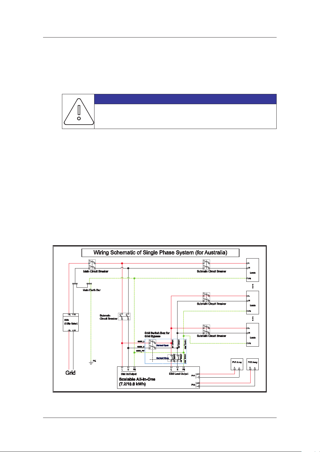
1. Grid Switch Box Wiring Schematic of Single Phase System for Australia
[Figure 5-17: Wiring Schematic of Single Phase System for Australia]
2. Assembling the Grid Switch Box
a. The components of the Grid Switch Box are as follows.
[Figure 5-18: Components of Grid Switch Box]
40
Page 49

NOTICE
Properly use the tting tools and apply the following torques as maximum
values:
For M4 - 1.5 Nm, for M6 - 5 Nm, for M8 - 20 Nm and for M10 - 40 Nm
When securing the handle, do not tighten the screw more than required.
Assemble the cable gland into the hole of the Grid Switch Box.
b.
5. Electrical Connections
[Figure 5-19: Assembling the Cable Gland]
NOTICE
The cable gland is not included in the product package.
For installation, it is required to be purchased separately.
The M25 x 1.5 mm product is recommended.
c. Check the wiring diagram of the Grid Switch Box.
[Figure 5-20: Wiring Diagram]
41
Page 50

CAUTION
To operate the product normally, be sure to wire according to [Figure 5-20].
Incorrect wiring may cause product malfunction.
d. Assemble the wires according to [Figure 5-20].
5. Electrical Connections
[Figure 5-21: Assembling the Wires]
e. Assemble the sealing nuts.
[Figure 5-22: Assembling the Sealing nuts]
42
Page 51

5. Electrical Connections
f. The nal assembly is as follows
[Figure 5-23: Final assembly]
Close the upper part of the Grid Switch Box and tighten the embedded screws.
g.
[Figure 5-24: Assembling the Upper Part]
Information
The screws in the upper part are already embedded in each hole.
43
Page 52

5. Electrical Connections
h. Assemble the rubber seal after aligning with the groove of the shaft.
[Figure 5-25: Assembling the Rubber Seal]
i. Assemble the knob after aligning with the groove of the shaft and tighten it with an
embedded screw.
[Figure 5-26: Assembling the Knob]
Information
The screw is already embedded in the knob.
44
Page 53

j. The nal assembly of the Grid Switch Box is as follows.
5. Electrical Connections
[Figure 5-27: Final Assembly]
45
Page 54

5. Electrical Connections
5.8 A Connecting Method of DC and AC Line
Refer to the [Figure 5-28] for the PV module connection. The lead wire coming from the PV
module is connected to the distribution box. For the structure of the distribution box, refer
to subsection 5.7. For the connection to the distribution box, connect each to the terminals
of the solar energy of PV1+, PV1-, PV2+, and PV2-. On the other hand, connect the
distribution box terminals with the main body terminals (PV1+
Scalable All in One in proper order. The lead wire thickness is presented shown in the
following Table.
For the connectors (PV1+, PV1-, PV2+, and PV2-) between the distribution box and the All in
One input, the following types of connectors are used (MC4 connector, PV-Stick Photovoltaic
connector
The [Table 5-7] shows the lead wire standard for the PV. The thickness (6mm
wire is recommended for the All in One.
“PUSH IN ”connection).
[Figure 5-28: PV connector (Female) and PV line (Male)]
, PV1-, PV2+, and PV2-) of the
2
) of the lead
Type Area Insulation Color code
PE 6 mm2 600 V or more Green with yellow lines
PV (+), (-) 6 mm2 700 V or more Black
[Table 5-7: Wire Standard]
[Figure 5-29: Load Connector (Male) and Grid Connector (Female)]
46
Page 55

5. Electrical Connections
[Figure 5-30: Connection of system for oating solar array, load and grid]
The Male product is connected to the lead wire coming from the distribution box in the PV
side, and the Female part is attached to the All in One system. The two products are properly
docked when connected together.
CAUTION
Damaged products must neither be installed nor put into operation.
Pay attention especially to awless seals.
The connectors are not for current interrupting.
Never connect or disconnect under load!
[Figure 5-31: PV connector connection (MC4 connector connection)]
47
Page 56

5. Electrical Connections
We recommend the cable composed of two power cords and one PE cord and have
insulation cover which contains all three cords as in the gure. Each cord shall be 6 mm
the diameter of the cable shall be approximately 18 mm
2
. Make sure that the PE cord is
2
longer than other live cords of the cable so that the PE cord will not be aected by the
pulling force. The PE terminal is connected to the PE of the sash to be ground connected.
and
[Figure 5-32: L and N AC line connection method]
48
Page 57

5.8.1 Mounting
1. Move housing over cable
2. Prepare conductor
3. Insert prepared conductors (with screw
connections: tighten screws, torque 2 Nm
(17.7 lbf-in) )
NOTE
Due to cold ow, extreme temperatures or temperature
variations may have a detrimental eect on the strain relief.
NOTE on Releasing Crimp Connections
a. Insert screwdriver (see detail)
b. Open latch by screwdriver
c. Take out cable
5. Electrical Connections
4. Insert contact insert into housing(note)
5. Turn contact insert until arrested.
6. Lock contact insert.
7. Tighten cable gland, torque
M32 gland: 12 Nm (106 lbf-in)
M40 gland: 14 Nm (124 lbf-in)
8. Plug in RST connector
9. Fasten bayonet
49
Page 58

Options
5. Electrical Connections
[Figure 5-33: Optional Actions]
CAUTION
Observe minimum bending radius of the cable (see illustration)!
Ensure the connector is not exposed to external forces (e.g. pull on the cable)
Through capillary forces, water in the sealing area of the cable gland can
enter the connectors. So, always run cables in a way that allows water to
drain o from the sealing area.
50
 Loading...