

Page 1
EN Instructions for use / assembly instructions
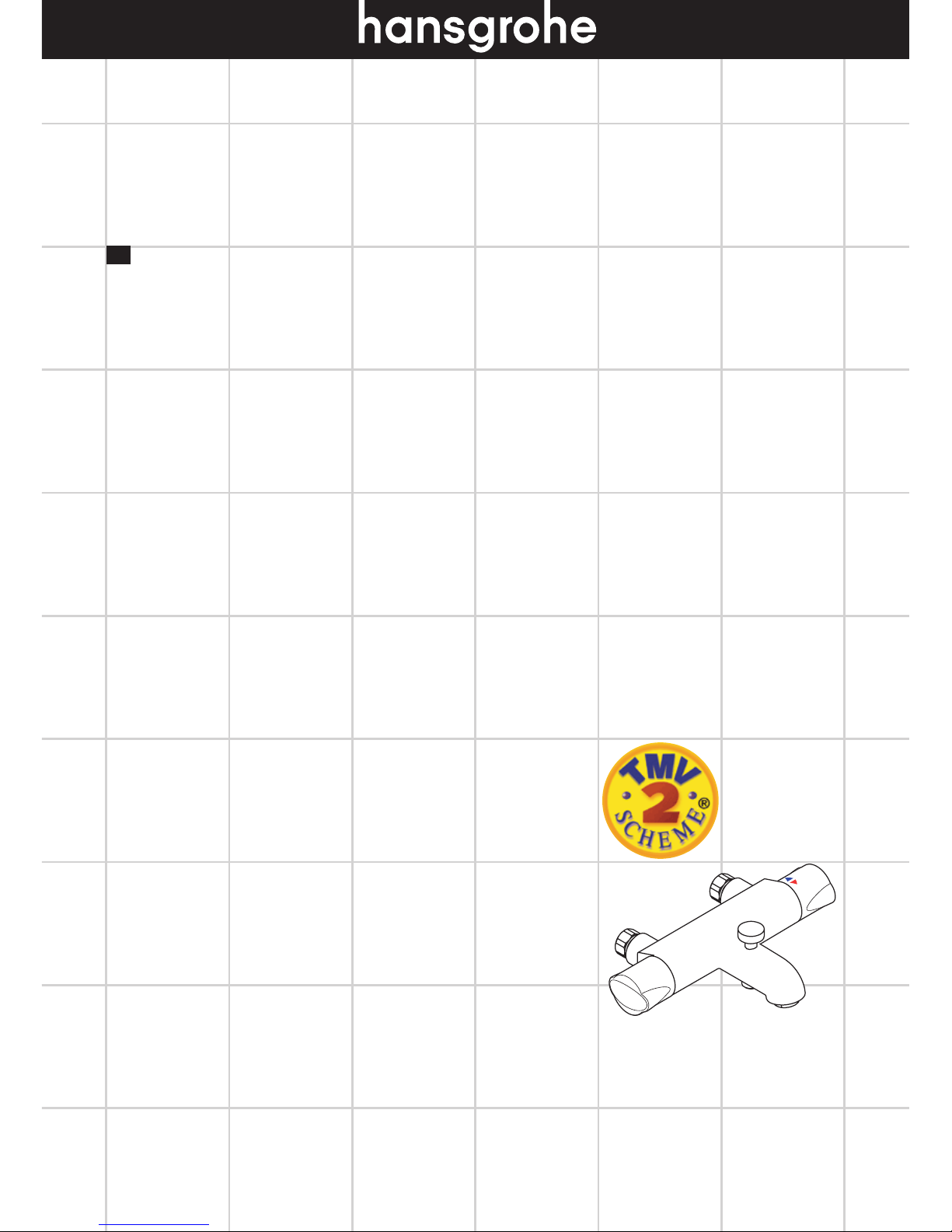
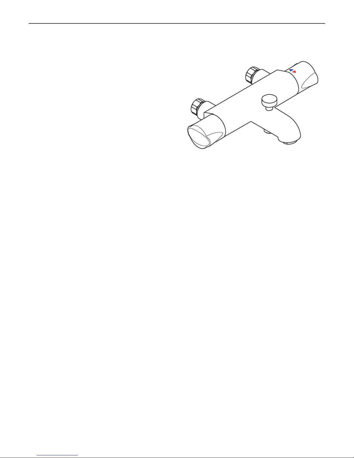
Ecomax
Bath / Shower
14242000
Page 2
Contents
Safety and Important Information 3
Pack Contents 4
Dimensions 4
Technical Data 5
Supply Conditions TMV2 5
Installation Requirements 6-7
Installation
Thermostat 8-9
Commissioning and in-service tests
Commissioning 10
In-service tests 11
Frequency of in-service tests 11
Thermostatic Adjustement
Temperature Limitation 12
Callibrating Thermostat 12 -13
Operating your Thermostat 14
Assembling and Operating the Diverter Fixing Device 15
Cleaning 16
Spare Parts 17
Test Certificate 17
Trouble Shooting 18
Warranty 19
If there are any queries regarding this product or its
installation, please contact the Hansgrohe technical
hotline: 01372465655
The Ecomax Bath / Shower 14242000 meets the
requirements of the TMV2 Scheme.
2
Page 3

3
Safety and Important Information
Hansgrohe products are safe provided they are
installed, used and maintained in accordance with these
instructions and recornrnendations.
Please read these instructions thoroughly and retain for
future use.
The plumbing installation of this thermostat mixing
valvemust comply with the requirements of UK
Water Regulations/Bylaws (Scotland), Building
Regulations or any other regulations specified by the
local Water Authority and supplier.
The installation of thermostatic mixing valves must
comply with the requirements of the Water Supply
(Water Fittings) Regulations 1999.
We strongly recommend that you use a plumber
registered with or a member of an Association:
Chartered Institute of Plumbing and Heating Engineering
(CIPHE)
Water Industry Approved Plumber Scheme (WIAPS)
Dispose of plastic bags carefully
Keep children well away from the work area.
Check for hidden pipes and cables in the wall before
drilling holes.
The unit must be mounted on a finished waterproofed
wall surface (usually tiles).
If you are using power tools (e.g. to drill holes) wear
safety glasses and always disconnect tools from the
power supply after use.
Do not operate the shower unit if the hand shower or
spray hose has been damaged or is blocked.
Do not block the flow of water from the hand shower, by
placing it on your hand or any other part of your body
or foreign object.
The thermostatic unit should be serviced annually by a
qualified person to ensure maximum safety during use.
The thermostatic mixing valve will be installed in such
a position that maintenance of the TMV and its valves
and the commissioning and testing of the TMV can be
undertaken.
The mixer is fitted with check valves (page 17
#94074000). There are filters on the thermostatic
element too (page 17 #94282000).
The fitting of isolation valves is required (preferred
location page 6 and 7 Installation Requirements)
Page 4
4
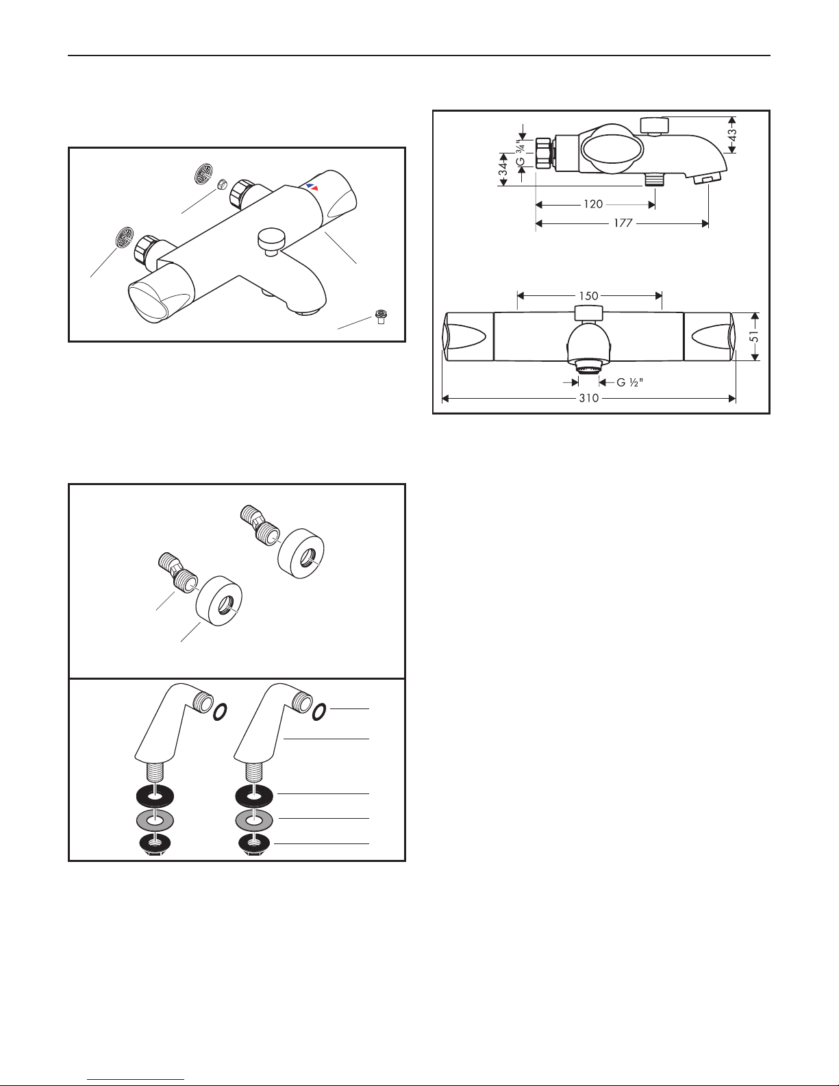
Pack Contents
Please check that you have been supplied with the
following:
Thermostat Bath / Shower
1 Ecomax Bath/Shower
2 Mesh washers
3 Flow limiter (when assembling the flow limiter, the
TMV2 certificate is invalid)
4 Diverter fixing device
Optional accessories
5 Escutcheons
6 S-unions
7 Pillar unions
8 Small seals
9 Large seals
10 Fixing nuts
11 Fibre washers
1
2
5
6
7
8
9
11
10
Dimensions
3
4
Page 5

5
Technical Data
This thermostatic valve will suit supplies of:
HIGH PRESSURE (HP-S-T)
Operating pressure: max. 10 bar
Recommended operating pressure: 1 - 5 bar
Test pressure: 16 bar
Hot water temperature: max. 70°C
Recommended hot water temp.: 65°C
Rate of flow: 36 l/min. @ 3 bar
Maximum outlet temperature: 43°C +/-*
Safety check: 40°C
Hot water connection: Left hand
Cold water connection: Right hand
Minimum difference between hot
water and mixed water temperature: 6 K
Hot and cold supply pressure should be balanced
Mixed water temperature
Application Mixed water temperature
(at point of discharge).
Bidet 38°C max.
Shower 41°C max.
Washbasin 41°C max.
Bath (44°C fill) 44°C max.
Bath (46°C fill) 46°C max.
* For preset outlet temperature adjustment – See page
14 „Commisioning“.
NB. If a water supply is fed by gravity then the supply
pressure should be verified to ensure the conditions of use
are appropriate for the valve. Valves operating outside of
these supply conditions cannot be guaranteed to operate
as a TMV2 valve.
Recommended outlet temperatures
The BuildCert TMV scheme recommends the following
set maximum mixed water outlet temperatures for use in
all premises:
44°C for bath fill but see notes below;
41°C for showers;
41°C for washbasins,
38°C for bidets.
The mixed water temperatures must never exceed 46°C.
The maximum mixed water temperature can be 2°C above
the recommended maximum set outlet temperatures.
Note: 46°C is the maximum mixed water temperature
from the bath tap. The maximum temperature takes account
of the allowable temperature tolerances inherent in thermostatic mixing valves and temperature losses in metal baths.
It is not a safe bathing temperature for adults or children.
The British Burns Association recommends 37 to 37.5°C
as a comfortable bathing temperature for children. In
premises covered by the Care Standards Act 2000, the
maximum mixed water outlet temperature is 43°C
Supply Conditions TMV2
Operating pressure range High pressure
Maximum static pressure - bar 10
Flow pressure, hot and cold - bar 0.5 to 5
Hot supply temperature - °C 55 to 65
Cold supply temperature - °C 5 to 25
Operating pressure range Low pressure
Maximum static pressure - bar 10
Flow pressure, hot and cold - bar 0.1 to 1
Hot supply temperature - °C 55 to 65
Cold supply temperature - °C 5 to 25
Page 6
6
Installation Requirements
This thermostatic mixer valve must be installed in
compliance with current Water Regulations. If you have
any doubts about the Water Regulation requirements
contact your local water services provider or use the
services of a professional plumber.
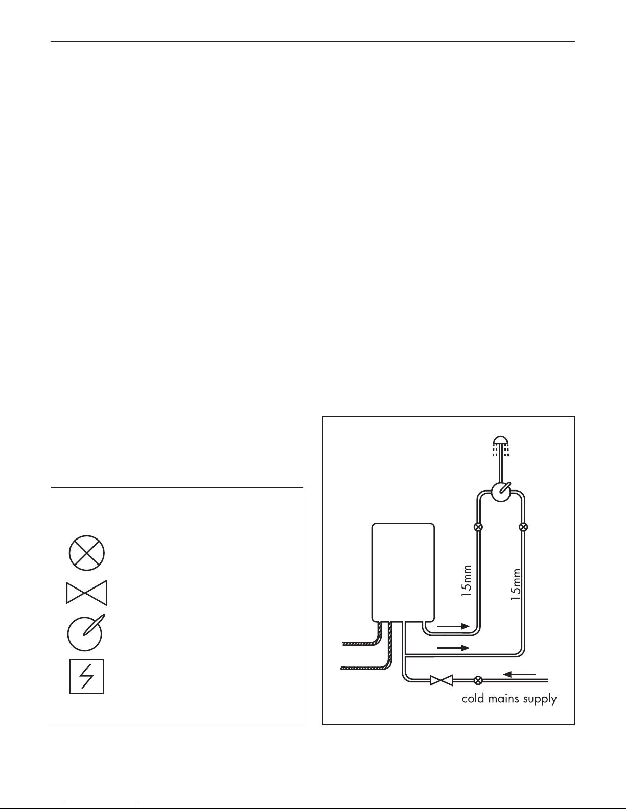
This mixer valve is suitable for use with the following
water supply systems:
Gas Combination Boiler (multi-point) 1.0 - 10 bar*
Unvented System (pressure balanced) 1.0 - 10 bar
Pumped System 1.0 - 10 bar
IMPORTANT: If you install this mixer with a gravity
fed system, there must be a minimum head (vertical
distance) from the underside of tlie cold water storage
tank to the showerhead position of at least 5 metre.
Before connecting the mixer, water should be flushed
through the system to remove all debris that might
otherwise damage the valve.
* If pressure is in excess of 3.5 bar, a pressure-reducing
valve should be fitted.
KEY
Isolating valve
Reducing valve
Mixer Valve
Pump
Gas Combination Boiler (multi-point)
Page 7

7
Unvented System (pressure balanced)
Pumped System
Page 8

8
Bath/Shower Thermostat
180 mm
Installation
36 - 39
mm
Seal
Shower Thermostat
PTFE
tape
150 mm
HOT
COLD
1 2
3
4
Page 9

9
Bath / Shower Thermostat (positioned over a bath)
The thermostatic mixing valve must be installed in a
position that is easily accessible for commissioning and
future servicing.
1. The hot and cold water outlets should be 150 mm
apart (plus or minus 12mm). Hot on the left and cold
on the right (fig. 1). The recommended plumbing
fittings are ½“ back plate elbows (not supplied).
2. Flush through the hot and cold water supplies.
3. Wrap PTFE tape round the S-unions and screw into the
backplate elbows. The S-unions must protrude beyond
the tiled surface between 32 and 41mm (figs.2-3).
4. Seal the gap between the S-unions and the tiles (fig.3).
5. Screw the escutcheons onto the S-unions.
6. Fasten the thermostatic mixer onto the S-unions using
the union nuts. Align the unit and tighten the nuts (be
careful not to damage the chrome finish). The S-unions
allow inaccuracies to be compensated for.
Bath/Shower Thermostat (Fitting to the bath using
pillar unions).
The thermostatic mixing valve must be installed in a
position that is easily accessible for commissioning and
future servicing.
1. The pillar unions are designed to fit tap holes on a
bath 180 mm apart with hot on the left and cold on
the right (fig.4).
2. Flush through the hot and cold water supplies.
3. Place fibre washers into the holes of the chrome union
nuts. (DO NOT USE FILTERS WHEN USING PILLAR
UNIONS!)
From under the bath fit a large seal washer over the
thread then fix with the nuts.
4. Fasten the mixer onto the union pillars using the union
nuts (be careful not to damage the chrome finish).
Page 10

10
f) record the equipment, thermometer etc. used for
the measurements
Table A: Guide to maximum stabilised tem-
peratures recorded during site tests
Application Mixed water
temperature
Shower 43°C
Washbasin 43°C
Bath (44°C fill) 46°C
Bath (46°C fill) 48°C
The mixed water temperature at terminal fitting should
never exceed 46ºC.
If there is a residual flow during the commissioning or
the annual verification (cold water supply isolation test),
then this is acceptable providing the temperature of
the water seeping from the valve is no more than 2°C
above the designated maximum mixed water outlet
temperature setting of the valve.
Temperature readings should be taken at the normal
flow rate after allowing for the system to stabilise.
The sensing part of the thermometer probe must be fully
submerged in the water that is to be tested.
Any TMV that has been adjusted or serviced must be
re-commissioned and re-tested in accordance with the
manufacturers' instructions.
Commissioning and in-service
tests
Commissioning
Purpose
Since the installed supply conditions are likely to be
different from those applied in the laboratory tests it is
appropriate, at commissioning, to carry out some simple
checks and tests on each mixing valve to provide a
performance reference point for future in-service tests.
Procedure
1. Check that:
a) the designation of the thermostatic mixing valve
matches the intended application
b) the supply pressures are within the range of ope-
rating pressures for the designation of the valve
c) the supply temperatures are within the range per-
mitted for the valve and by guidance information
on the prevention of legionella etc.
2. Adjust the temperature of the mixed water in accor-
dance with the manufacturer’s instructions and the
requirement of the application and then carry out the
following sequence:
a) record the temperature of the hot and cold water
supplies
b) record the temperature of the mixed water at the
largest draw-off flow rate
c) record the temperature of the mixed water at a
smaller draw-off flow rate, which shall be measured
d) isolate the cold water supply to the mixing valve
and monitor the mixed water temperature
e) record the maximum temperature achieved as a
result of (d) and the final stabilised temperature
NOTE: The final stabilised mixed water temperature
should not exceed the values in Table A.
Page 11

11
In-service tests
Purpose
The purpose of in-service tests is to regularly monitor
and record the performance of the thermostatic mixing
valve. Deterioration in performance can indicate the
need for service work on the valve and/ or the water
supplies.
Procedure
1. Carry out the procedure 2. (a) to (e) on page 72
using the same measuring equipment, or equipment
to the same specifications.
2. If the mixed water temperature has changed signi-
ficantly from the previous test results (e.g. > 1 K),
record the change and before re-adjusting the mixed
water temperature check:
a) that any in-line or integral strainers are clean
b) any in-line or integral check valves or other
anti-backsiphonage devices are in good working
order
c) any isolating valves are fully open
3. With an acceptable mixed water temperature, complete the procedure 2. (a) to (c) on page 10.
4. If at step 2. (e) on page 10 the final mixed water tem-
perature is greater than the values in Table A and / or
the maximum temperature exceeds the corresponding
value from the previous test results by more than about
2 K, the need for service work is indicated.
NOTE: In-service tests should be carried out with a
frequency which identifies a need for service work
before an unsafe water temperature can result. In
the absence of any other instruction or guidance, the
procedure described in „Frequency of in-service tests“
may be used.
Frequency of in-service tests TMV2
The frequency of performing the in-service
tests is 1 year maximum.
General
In the absence of any other instruction or guidance on
the means of determining the appropriate frequency of
in-service testing, the following procedure may be used:
1. 6 to 8 weeks after commissioning carry out the tests
given in 2. on page 10.
2. 12 to 15 weeks after commissioning carry out the tests
given in 2. on page 10.
3. Depending on the results of 1. and 4. several possibilities exist:
a) If no significant changes (e.g. < 1 K) in mixed
water temperatures are recorded between commissioning and 1., or between commissioning and
4. the next in-service test can be deferred to 24
to 28 weeks after commissioning.
b) If small changes (e.g. 1 to 2 K) in mixed water
temperatures are recorded in only one of these periods, necessitating adjustment of the mixed water
temperature, then the next in-service test can be
deferred to 24 to 28 weeks after commissioning.
c) If small changes (e.g. 1 to 2 K) in mixed water
temperatures are recorded in both of these periods, necessitating adjustment of the mixed water
temperature, then the next in-service test should be
carried out at 18 to 21 weeks after commissioning.
d) If significant changes (e.g. > 2 K) in mixed water
temperatures are recorded in either of these
periods, necessitating service work, then the next
in-service test should be carried out at 18 to 21
weeks after commissioning.
4. The general principle to be observed after the first 2 or
3 in-service tests is that the intervals of future tests should
be set to those which previous tests have shown can be
achieved with no more than a small change in mixed
water temperature.
Page 12

12
SW 3 mm
1
2
3
Thermostatic Adjustment
Temperature Limitation
The temperature is limited by the safety stop to 40°C.
If a higher temperature is required, it is possible to over
ride the safety stop by depressing the safety button.
NB. It is recommended that for private domestic
use the maximum mixed water temperature be set at the
following factory set values:
Shower Mixer 43°C
Bath/Shower 46°C
Bath/Shower Mixer when installed as type 3 valve the
maximum mixed water temperature shall be set at 43°C
for both outlets (bath & shower)
Temperatures can be set by following the procedures
under „Setting thermostat to a maximum tem-
perature“. This ensures that after correct installation
the outlet temperature of the water can never exceed
43°C.
To guarantee a smooth running of the thermostatic
element, it is necessary from time to time to turn the thermostat from total hot to total cold. The thermostatic mixer
valve should be checked annually by a qualified person
to ensure correct operation.
The mixer is fitted with check valves (page 17
#96644000) and filters (page 17 #96922000). If the
water flow drops the filters need to be cleaned. For that
purpose the mixer has to be removed from the wall.
Calibrating Thermostat
1. If the temperature reading is different to the
showering temperature, turn the thermostat
handle until a 40°C reading is shown on your thermometer.
2. Remove the handle end cap, undo the screw (fig. 1).
3. Pull off the handle (fig. 2).
4. Remove the circlip from the spindle and slide off the
locking ring (fig. 3).
Page 13

13
SW 3 mm
(2 Nm)
4
5
6
5. Turn the spindle until the required maximum temperature is reached (40°C). You will need to use a
thermometer (fig. 4).
6. Replace the locking ring back onto the spindle as
shown. Refit the circlip (fig. 5).
7. Replace the handle, screw and end cap
(fig. 6).
Page 14

14
Operating your Thermostat
Flow ON/OFF Control
Turn the flow control handle (fig.1a) anti-clockwise to
turn the water on and to increase the flow. Turn it clockwise to decrease the flow and turn off.
Temperature Control
Turn the temperature control handle (fig. 1b) anti-clockwise to increase the water temperature and clockwise to
decrease the water temperature.
Thermostat
The valve automatically adjusts for changes in flow
supply and maintains the outlet set water temperature.
Using Bath / Shower Diverter
When first turned on, the water flow automatically
comes from the bath tap.
To divert the water flow to the hand shower, pull up the
diverter knob (fig. 2).
To divert the water flow to the bath tap, push down on
the diverter knob (fig. 3).
a
b
1
2
3
Page 15

15
Assembling and Operating the
Diverter Fixing Device
If the Bath / Shower Diverter does not work perfect, please
assemble the diverter fixing device.
To remove the diverter knob, fix the diverter from below
with a screw driver and screw off the diverter knob (fig. 1).
Assemble the diverter fixing device (fig. 2).
Assemble the diverter knob (fig. 3).
To divert the water flow to the hand shower, pull up the
diverter knob and turn 90° clockwise (fig. 4).
To divert the water flow to the bath tap, turn the diverter
knob 90° counter clockwise and push down (fig. 5).
1
2 3
90°
1.
2.
90°
4
5
Page 16

16
Cleaning
Cleaning Recommendation for Hansgrohe
Products
Today, modern sanitary and kitchen tapware, showers,
accessories, washstands, sinks, tubs and radiators consist
of very different materials to comply with the needs of
the market with regard to design and functionality.
To avoid damage and reclamations, it is necessary to
consider certain criteria when cleaning.
With regard to caring for the Hansgrohe
products, the following must in principle be
heeded:
• Only use cleaning material which is explicitly provided
for this type of application.
• Never use cleaning materials, which contain
hydrochloric acid, formic acid, concentrated caustic
soda, chlorine pale lye or acetic acid, as they cause
considerable damage.
• Phosphorus acidic cleaners are only conditionally
applicable.
• Mixing cleaning agents is not permitted, generally.
• Never use cleaning materials or appliances with an
abrasive effect, such as unsuitable cleaning powders,
sponge pads or micro fibre cloths.
• The instructions of the cleaning agent manufacturers
have to be followed absolutely.
• Cleaning has to be carried out with a specified
cleaner dosage, contact time, object-related and
adapted to the needs.
• The building up of calcifications has to be removed by
cleaning regulary.
• When using spray cleaners, spray the cleaning
solution onto a soft cloth or sponge, never directly
onto the Hansgrohe products, as the atomised spray
could enter openings and gaps in the Hansgrohe
products and cause damage.
• After cleaning rinse thoroughly with clean water to
remove any cleaner residue.
• The use of steam cleaners is not permitted. The high
temperatures can damage the products.
Important
Residues of toiletries such as liquid soaps, shampoos and
shower gels, hair dyes, perfumes, aftershave and nail
varnish can also cause damage.
Here too: Carefully rinse with water after use to remove
residues.
Likewise, do not store any cleaning agents or chemicals
under the products, for example in a vanity unit, as the
vapours may damage the products.
The damage of already damaged surfaces will
deteriorate under the effect of the cleansers.
Components with damaged surfaces must be
exchanged, otherwise there could be an injury
danger.
Page 17

17
Spare Parts
Ecomax
Bath / Shower
14242000
96633000
92929000
97469000
97335000
97163000
96488000
97164000
97210000
96922000
97211000
96644000
97510000
98163000
(15x2)
98421000
(28x1,5)
Test Certificate
WRAS
14242000
X
Page 18

18
Fault Cause Remedy
Insufficient water - Supply pressure inadequate - Check water pressure (If a pump
has been installed check to see if
the pump is working).
- Shower filter seal dirty - Clean filter insert between shower
and hose
- Filters are dirty #96922000 - Clean the filter / exchange filter
Crossflow, hot water being forced
into cold water pipe, or vice versa,
when mixer is closed
- Backflow preventers dirty or leaking - Clean backflow preventers,
exchange if necessary
Spout temperature does not
correspond with temperature set
- Thermostat has not been adjusted - Adjust thermostat
- Hot water temperature too low - Increase hot water temperature to
42 ºC to 65 ºC
Temperature regulation not possible - thermo cartridge calcified - Exchange cartridge
Shower or spout dripping - Dirt or sedimentation on valve seat,
shut-off unit damaged
- Clean or exchange shut-off unit
Trouble Shooting
Page 19

19
Warranty
Hansgrohe guarantees to the consumer that this product is free of production faults. If nevertheless any defect is
detected within 5 years from date of purchase, Hansgrohe will remedy this defect free of charge. You will find the
conditions and details of this guarantee at www.hansgrohe-int.com/guarantee. Please contact your contracting party
to claim your rights under this guarantee. This guarantee does not affect the customer‘s rights under the respective
national legislation.
Technical Hotline E-mail
01372465655 Technical@hansgrohe.co.uk
Page 20

20
Hansgrohe · Units D1 & D2 Sandown Park · Park Trading Estate, Royal Mills · Esher Surrey KT10 8BL · Technical Hotline 01372465655
E-Mail: technical@hansgrohe.co.uk · Internet: www.hansgrohe.co.uk
07/2018
9.05577.04
 Loading...