

Page 1

DE Gebrauchsanleitung / Montageanleitung 2
EN Instructions for use / assembly instructions 4
Ecomax
13356000
Ecomax
13354000
Page 2

Sicherheitshinweise
Bei der Montage müssen zur Vermeidung von Quetsch-
und Schnittverletzungen Handschuhe getragen werden.
Das Produkt darf nur zu Bade-, Hygiene- und Körper-
reinigungszwecken eingesetzt werden.
Kinder, sowie Erwachsene mit körperlichen, geis-
tigen und / oder sensorischen Einschränkungen
dürfen das Produkt nicht unbeaufsichtigt benutzen.
Personen, die unter Alkohol- oder Drogeneinfluss
stehen, dürfen das Produkt nicht benutzen.
Große Druckunterschiede zwischen den Kalt- und
Warmwasseranschlüssen müssen ausgeglichen
werden.
Montagehinweise
• Vor der Montage muss das Produkt auf Transportschäden untersucht werden. Nach dem Einbau werden
keine Transport- oder Oberflächenschäden anerkannt.
• Die Leitungen und die Armatur müssen nach den gültigen Normen montiert, gespült und geprüft werden.
• Die in den Ländern jeweils gültigen Installationsrichtlinien sind einzuhalten.
Thermostat in Verbindung mit Durchlauferhitzern
• Wird eine Handbrause angeschlossen, so muss aus
dieser eine eventuell vorhandene Drossel ausgebaut
werden.
• Bei Problemen mit dem Durchlauferhitzer oder großen
Druckunterschieden muss eine optional erhältliche
Drossel (Artikelnummer 97510000) in den Kaltwasserzulauf eingesetzt werden.
Technische Daten
Betriebsdruck: max. 1 MPa
Empfohlener Betriebsdruck: 0,1 - 0,5 MPa
Prüfdruck: 1,6 MPa
(1 MPa = 10 bar = 147 PSI)
Heißwassertemperatur: max. 70°C
Empfohlene Heißwassertemperatur: 65°C
Thermische Desinfektion: max. 70°C / 4 min
Durchflussleistung Wanneneinlauf: 58 l/min 0,3 MPa
Durchflussleistung Abgang Brause: 18 l/min 0,3 MPa
• Eigensicher gegen Rückfließen
• Das Produkt ist ausschließlich für Trinkwasser konzipiert!
Deutsch
Justierung (siehe Seite 9)
Nach erfolgter Montage muss die Auslauftemperatur des Thermostaten überprüft werden. Eine Korrektur ist erforderlich wenn die
an der Entnahmestelle gemessene Temperatur von der am Thermostaten eingestellten
Temperatur abweicht.
Kein essigsäurehaltiges Silikon verwenden!
Symbolerklärung
Wartung (siehe Seite 11 )
• Rückflussverhinderer müssen gemäß DIN
EN 1717 regelmäßig in Übereinstimmung
mit nationalen oder regionalen Bestimmungen auf ihre Funktion geprüft werden
(mindestens einmal jährlich).
• Um die Leichtgängigkeit der Regeleinheit
zu gewährleisten, sollte der Thermostat
von Zeit zu Zeit auf ganz warm und ganz
kalt gestellt werden.
Safety Function (siehe Seite 10)
Dank der Safety Function lässt sich die gewünschte Höchsttemperatur von z. B. max.
42 ºC voreinstellen.
2
Page 3
Deutsch
Serviceteile (siehe Seite 14)
Bedienung (siehe Seite 12)
Maße (siehe Seite 8)
Reinigung (siehe Seite 20)
Montage (siehe Seite 6)
Störung Ursache Abhilfe
Wenig Wasser - Versorgungsdruck nicht ausreichend - Leitungsdruck prüfen
- Schmutzfangsieb der Regeleinheit
verschmutzt
- Schmutzfangsiebe vor dem Thermostat und auf der Regeleinheit
reinigen
- Siebdichtung der Brause verschmutzt
- Siebdichtung zwischen Brause und
Schlauch reinigen
Kreuzfluss, warmes Wasser wird
bei geschlossener Armatur in die
Kaltwasserleitung gedrückt oder
umgekehrt
- Rückflussverhinderer verschmutzt /
defekt
- Rückflussverhinderer reinigen ggf.
austauschen
Auslauftemperatur stimmt nicht mit
der eingestellten Temperatur überein
- Thermostat wurde nicht justiert - Thermostat justieren
- Zu niedrige Warmwassertemperatur - Warmwassertemperatur erhöhen
auf 42 ºC bis 65 ºC
Temperaturregelung nicht möglich - Regeleinheit verkalkt - Regeleinheit austauschen
Durchlauferhitzer schaltet bei Thermostatbetrieb nicht ein
- Schmutzfangsiebe verschmutzt - Schmutzfangsiebe reinigen / austauschen
- Rückflussverhinderer sitzt fest - Rückflussverhinderer austauschen
- Drossel in der Handbrause nicht
ausgebaut
- Drossel aus der Handbrause entfernen
Brause oder Auslauf tropft - Schmutz oder Ablagerungen auf
dem Dichtsitz, Absperroberteil beschädigt
- Absperroberteil reinigen bzw. austauschen
3
Prüfzeichen (siehe Seite 8)
Page 4
Safety Notes
Gloves should be worn during installation to prevent
crushing and cutting injuries.
The product may only be used for bathing, hygienic
and body cleaning purposes.
Children as well as adults with physical, mental and/
or sensoric impairments must not use this product
without proper supervision. Persons under the influence of alcohol or drugs are prohibited from using
this product.
The hot and cold supplies must be of equal pres-
sures.
Installation Instructions
• Prior to installation, inspect the product for transport
damages. After it has been installed, no transport or
surface damage will be honoured.
• The pipes and the fixture must be installed, flushed
and tested as per the applicable standards.
• The plumbing codes applicable in the respective
countries must be observed.
Thermostatic mixer in conjunction with
combination boilers
• If fitting a hand shower remove the water limiter from
the shower.
• If the continuous water heater causes any problems,
or you have different water pressures you must
install a water limiter to the cold supply, (ordered
separately,article number 97510000).
Technical Data
Operating pressure: max. 1 MPa
Recommended operating pressure: 0,1 - 0,5 MPa
Test pressure: 1,6 MPa
(1 MPa = 10 bar = 147 PSI)
Hot water temperature: max. 70°C
Recommended hot water temp.: 65°C
Thermal disinfection: max. 70°C / 4 min
Rate of flow Bath Spout: 58 l/min 0,3 MPa
Rate of flow Shower outlet: 18 l/min 0,3 MPa
• Safety against backflow
• The product is exclusively designed for drinking water!
English
Adjustment (see page 9)
After the installation, the output temperature of the thermostat must be checked. A
correction is necessary if the temperature
measured at the output differs from the
temperature set on the thermostat.
Do not use silicone containing acetic acid!
Symbol description
Maintenance (see page 11 )
• The check valves must be checked
regularly according to DIN EN 1717 in
accordance with national or regional
regulations (at least once a year).
• To guarantee the smooth running of the
thermostat, it is necessary from time to
time to turn the thermostat from total hot
to total cold.
Safety Function (see page 10)
The desired maximum temperature for example max. 42º C can be pre-set thanks to the
safety function.
4
Page 5
English
Spare parts (see page 14)
Operation (see page 12)
Dimensions (see page 8)
Cleaning (see page 20)
Assembly (see page 6)
Fault Cause Remedy
Insufficient water - Supply pressure inadequate - Check water pressure (If a pump
has been installed check to see if
the pump is working).
- Regulator filter dirty - Clean filter in front of the mixer and
on the MTC-thermo cartridge
- Shower filter seal dirty - Clean filter seal between shower
and hose
Crossflow, hot water being forced
into cold water pipe, or vice versa,
when mixer is closed
- Backflow preventers dirty or leaking - Clean backflow preventers, exchange if necessary
Spout temperature does not correspond with temperature set
- Thermostat has not been adjusted - Adjust thermostat
- Hot water temperature too low - Increase hot water temperature to
42 ºC to 65 ºC
Temperature regulation not possible - thermo cartridge calcified - Exchange thermo cartridge
Instantaneous heater didn't work with
thermostat
- Filters are dirty - Clean the filter / exchange filter
- check valve hasn't moved back - Exchange check valves
- Flow limiter in handshower isn’t
removed
- Remove flow limiter
Shower or spout dripping - Dirt or sedimentation on valve seat,
shut-off unit damaged
- Clean or exchange shut-off unit
Special information for UK (see page 15)
5
Test certificate (see page 8)
Page 6
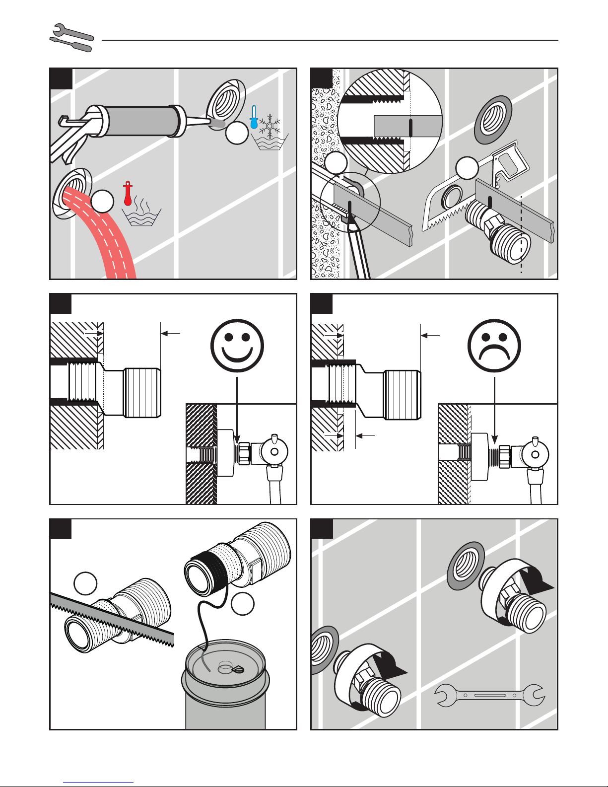
6
X
X + 36 mm
X 36
1
3b
2
3a
1.
2.
1.
2.
Silicone
max.
39 mm
max.
5 mm
1.
2.
5
4
36 mm
SW 24 mm
Page 7

7
6
7
8
SW 30 mm
(17 Nm)
Page 8

8
Ecomax
13354000
Ecomax
13356000
R 1/2
R 1/2
P-IX DVGW SVGW ACS WRAS ETA KIWA
13354000
X
13356000
X
Page 9

9
SW 3 mm
SW 3 mm
(2 Nm)
1
3 4
2
5 6
Page 10

10
z. B. 42° C
for example 42° C
43
1 2
5
1.
2.
SW 3mm
SW 3mm
(2 Nm)
Page 11

11
5 6
SW 30 mm
SW 30 mm
(17 Nm)
SW 12 mm
SW 12 mm
(20 Nm)
4
1.
1.
2.
2.
3
1 2
SW 24 mm
1.
2.
SW 24 mm
(20 Nm)
1.
2.
Page 12

12
1
2
3
Page 13

13
schließen / close
90°
öffnen / open
1.
2.
kalt / cold
> 40°C
warm /hot
90°
1.
2.
Page 14

14
Ecomax
13354000
94140000
96429000
98163000
(15x2)
96467000
96922000
97220000
96644000
(OV25 / DN25)
98194000
(28x2)
96157000
97210000
96466000
96225000
97163000
97738000
97211000
(25x2)
97164000
95041000
96633000
98147000
(26x2)
(34x2)
(38x2,5)
A
96264000
97162000
92929000
96264000
Ecomax
13356000
94140000
96429000
98163000
(15x2)
96157000
96467000
96922000
97220000
96644000
(OV25 / DN25)
98194000
(28x2)
97210000
97162000
92929000
96264000
98147000
(26x2)
(34x2)
(38x2,5)
A
96264000
96225000
95041000
96633000
98556000
97664000
(M5x25)
98140000
(20x1)
Page 15

15
Safety and Important Information
Hansgrohe products are safe provided they are installed,
used and maintained in accordance with these instructions
and recornrnendations.
Please read these instructions thoroughly and retain for
future use.
The plumbing installation of this thermostat mixing valvemust
comply with the requirements of UK
Water Regulations/Bylaws (Scotland), Building Regulations or any other regulations specified by the local Water
Authority and supplier.
The installation of thermostatic mixing valves must comply
with the requirements of the Water Supply (Water Fittings)
Regulations 1999.
We strongly recommend that you use a plumber registered
with or a member of an Association:
Chartered Institute of Plumbing and Heating Engineering
(CIPHE)
Water Industry Approved Plumber Scheme (WIAPS)
Dispose of plastic bags carefully
Keep children well away from the work area.
Check for hidden pipes and cables in the wall before
drilling holes.
The unit must be mounted on a finished waterproofed wall
surface (usually tiles).
If you are using power tools (e.g. to drill holes) wear safety glasses and always disconnect tools from the power
supply after use.
Do not operate the shower unit if the hand shower or spray
hose has been damaged or is blocked.
Do not block the flow of water from the hand shower, by
placing it on your hand or any other part of your body or
foreign object.
The thermostatic unit should be serviced annually by a
qualified person to ensure maximum safety during use.
The thermostatic mixing valve will be installed in such a
position that maintenance of the TMV and its valves and the
commissioning and testing of the TMV can be undertaken.
The mixer is fitted with check valves (page 14 pos.
96644000). There are filters on the thermostatic element
too (page 14 pos. A and 96922000).
The fitting of isolation valves is required (preferred location
page 17 Installation Requirements)
On the following pages 16 - 21 you can
find important information only for the
installation in UK
Technical Hotline for UK only 01372465655
E-mail for UK only Technical@hansgrohe.co.uk
(Diese Servicehotline ist nur für das Vereinigte Königreich Großbritannien, nicht z. B. für Deutschland)
Page 16

16
Technical Data
This thermostatic valve will suit supplies of:
13354000: High pressure (HP-S/ T41) / Low pressure
(LP-S)
13356000: High pressure (HP-S) / Low pressure (LP-S)
Operating pressure: max. 10 bar
Recommended operating pressure: 0.2 - 5 bar
Test pressure: 16 bar
Hot water temperature: max. 80°C
Recommended hot water temp.: 65°C
Rate of flow from bath spout: 58 l/min. @ 3 bar
Rate of flow from shower outlet: 18 l/min. @ 3 bar
Maximum outlet temperature: 43°C +/-*
Safety check: 40°C
Hot water connection: Left hand
Cold water connection: Right hand
Minimum difference between hot
water and mixed water temperature: 6 K
Hot and cold supply pressure should be balanced
Mixed water temperature
Application Mixed water temperature
(at point of discharge).
Shower 41°C max.
Washbasin 41°C max.
Bath (44°C fill) 44°C max.
Bath (46°C fill) 46°C max.
* For preset outlet temperature adjustment – See page 10.
NB. If a water supply is fed by gravity then the supply
pressure should be verified to ensure the conditions of use
are appropriate for the valve. Valves operating outside of
these supply conditions cannot be guaranteed to operate
as a TMV2 or TMV3 valve.
Recommended outlet temperatures
The BuildCert TMV scheme recommends the following
set maximum mixed water outlet temperatures for use in
all premises:
44°C for bath fill but see notes below;
41°C for showers;
41°C for washbasins.
The mixed water temperatures must never exceed 46°C.
The maximum mixed water temperature can be 2°C above
the recommended maximum set outlet temperatures.
Note: 46°C is the maximum mixed water temperature from
the bath tap. The maximum temperature takes account of the
allowable temperature tolerances inherent in thermostatic
mixing valves and temperature losses in metal baths.
It is not a safe bathing temperature for adults or children.
The British Burns Association recommends 37 to 37.5°C as
Installation Requirements
This thermostatic mixer valve must be installed in compliance with current Water Regulations. If you have any
doubts about the Water Regulation requirements contact
your local water services provider or use the services of a
professional plumber.
The thermostatic mixing valve must be installed in a position that is easily accessible for commissioning and future
servicing.
This mixer valve is suitable for use with the following water
supply systems:
Gas Combination Boiler (multi-point) 1.0 - 10 bar*
Unvented System (pressure balanced) 1.0 - 10 bar
Pumped System 1.0 - 10 bar
IMPORTANT: If you install this mixer with a gravity fed
system, there must be a minimum head (vertical distance)
from the underside of tlie cold water storage tank to the
showerhead position of at least 5 metre.
Before connecting the mixer, water should be flushed
through the system to remove all debris that might otherwise
damage the valve.
* If pressure is in excess of 3.5 bar, a pressure-reducing
valve should be fitted.
a comfortable bathing temperature for children. In premises
covered by the Care Standards Act 2000, the maximum
mixed water outlet temperature is 43°C
Supply Conditions TMV2
Operating pressure range
High
pressure
Low
pressure
Maximum static pressure - bar 10 10
Flow pressure, hot and cold - bar 1 to 5 0.2 to 1
Hot supply temperature - °C 52 to 65 52 to 65
Cold supply temperature - °C 5 to 20 5 to 20
Supply Conditions TMV3
Operating pressure range
High
pressure
Low
pressure
Maximum static pressure - bar 10 10
Flow pressure, hot and cold - bar 0.5 to 5 0.1 to 1
Hot supply temperature - °C 55 to 65 55 to 65
Cold supply temperature - °C 5 to 25 5 to 25
Page 17

17
KEY
Isolating valve
Reducing valve
Mixer Valve
Pump
Gas Combination Boiler (multi-point)
Unvented System (pressure balanced)
Pumped System
Page 18

18
peratures recorded during site tests
Application Mixed water
temperature
Shower 43°C
Washbasin 43°C
Bath (44°C fill) 46°C
Bath (46°C fill) 48°C
The mixed water temperature at terminal fitting should
never exceed 46ºC.
If there is a residual flow during the commissioning or
the annual verification (cold water supply isolation test),
then this is acceptable providing the temperature of the
water seeping from the valve is no more than 2°C above
the designated maximum mixed water outlet temperature
setting of the valve.
Temperature readings should be taken at the normal flow
rate after allowing for the system to stabilise.
The sensing part of the thermometer probe must be fully
submerged in the water that is to be tested.
Any TMV that has been adjusted or serviced must be
re-commissioned and re-tested in accordance with the
manufacturers' instructions.
Commissioning and in-service tests
Commissioning
Purpose
Since the installed supply conditions are likely to be different
from those applied in the laboratory tests it is appropriate,
at commissioning, to carry out some simple checks and tests
on each mixing valve to provide a performance reference
point for future in-service tests.
Procedure
1. Check that:
a) the designation of the thermostatic mixing valve
matches the intended application
b) the supply pressures are within the range of ope-
rating pressures for the designation of the valve
c) the supply temperatures are within the range per-
mitted for the valve and by guidance information
on the prevention of legionella etc.
2. Adjust the temperature of the mixed water in accordance with the manufacturer’s instructions (page 10)
and the requirement of the application and then carry
out the following sequence:
a) record the temperature of the hot and cold water
supplies
b) record the temperature of the mixed water at the
largest draw-off flow rate
c) record the temperature of the mixed water at
a smaller draw-off flow rate, which shall be
measured
d) isolate the cold water supply to the mixing valve
and monitor the mixed water temperature
e) record the maximum temperature achieved as a
result of (d) and the final stabilised temperature
NOTE: The final stabilised mixed water temperature
should not exceed the values in Table A.
f) record the equipment, thermometer etc. used for
the measurements
Table A: Guide to maximum stabilised tem-
Page 19

19
In-service tests
Purpose
The purpose of in-service tests is to regularly monitor and
record the performance of the thermostatic mixing valve.
Deterioration in performance can indicate the need for
service work on the valve and/ or the water supplies.
Procedure
1. Carry out the procedure 2. (a) to (e) on page 18 using
the same measuring equipment, or equipment to the
same specifications.
2. If the mixed water temperature has changed significantly from the previous test results (e.g. > 1 K), record
the change and before re-adjusting the mixed water
temperature check:
a) that any in-line or integral strainers are clean
b) any in-line or integral check valves or other anti-
backsiphonage devices are in good working order
c) any isolating valves are fully open
3. With an acceptable mixed water temperature, complete the procedure 2. (a) to (e) on page 18.
4. If at step 2. (e) on page 18 the final mixed water temperature is greater than the values in Table A and / or
the maximum temperature exceeds the corresponding
value from the previous test results by more than about
2 K, the need for service work is indicated.
NOTE: In-service tests should be carried out with a
frequency which identifies a need for service work
before an unsafe water temperature can result. In
the absence of any other instruction or guidance, the
procedure described in „Frequency of in-service tests“
may be used.
Frequency of in-service tests
TMV3*
General
In the absence of any other instruction or guidance on
the means of determining the appropriate frequency of
in-service testing, the following procedure may be used:
1. 6 to 8 weeks after commissioning carry out the tests
given in 2. on page 18.
2. 12 to 15 weeks after commissioning carry out the tests
given in 2. on page 18.
3. Depending on the results of 1. and 4. several possibilities exist:
a) If no significant changes (e.g. < 1 K) in mixed
water temperatures are recorded between commissioning and 1., or between commissioning and
4. the next in-service test can be deferred to 24 to
28 weeks after commissioning.
b) If small changes (e.g. 1 to 2 K) in mixed water
temperatures are recorded in only one of these periods, necessitating adjustment of the mixed water
temperature, then the next in-service test can be
deferred to 24 to 28 weeks after commissioning.
c) If small changes (e.g. 1 to 2 K) in mixed water
temperatures are recorded in both of these periods, necessitating adjustment of the mixed water
temperature, then the next in-service test should be
carried out at 18 to 21 weeks after commissioning.
d) If significant changes (e.g. > 2 K) in mixed water
temperatures are recorded in either of these
periods, necessitating service work, then the next
in-service test should be carried out at 18 to 21
weeks after commissioning.
4. The general principle to be observed after the first 2
or 3 in-service tests is that the intervals of future tests
should be set to those which previous tests have shown
can be achieved with no more than a small change in
mixed water temperature.
*TMV2: The frequency of performing the in-
service tests is 1 year maximum.
Page 20

Thermostatic Adjustment
Temperature Limitation
The temperature is limited by the safety stop to 40°C. If
a higher temperature is required, it is possible to over ride
the safety stop by depressing the safety button.
NB. It is recommended that for private domestic use
the maximum mixed water temperature be set at the following factory set values:
Shower Mixer 43°C
Bath/Shower 43°C
Temperatures can be set by following the procedures on
page 9. This ensures that after correct installation the outlet
temperature of the water can never exceed 43°C.
To guarantee a smooth running of the thermostatic element,
it is necessary from time to time to turn the thermostat from
total hot to total cold. The thermostatic mixer valve should
be checked annually by a qualified person to ensure
correct operation.
The mixer is fitted with check valves (page 14 pos.
96644000) and filters (page 14 pos. A and 96922000).
If the water flow drops the filters need to be cleaned. For
that purpose please follow the steps 1 - 8 on page 10.
Calibrating Thermostat
If the temperature reading is different to the showering
temperature, follow the steps 1 - 6 on page 8.
Hansgrohe · Auestraße 5 - 9 · D-77761 Schiltach · Telefon +49 (0) 78 36/51-1282 · Telefax +49 (0) 7836/511440
E-Mail: info@hansgrohe.com · Internet: www.hansgrohe.com
07/2018
9.05016.04
20
ww
w.hansgr
ohe.com/
cleaning-recommendation
ww
w.hansgr
ohe.com/
cleaning-recommendation
www.hansgrohe.com/
cleaning-recommendation
www.hansgrohe.com/
cleaning-recommendation
ww
w.hansgr
ohe.com/
cleaning-recommendation
www.hansgrohe.com/
cleaning-recommendation
www.hansgrohe.com/
cleaning-recommendation
ww
w.hansgr
ohe.com/
cleaning-recommendation
www.hansgrohe.com/
cleaning-recommendation
www.hansgrohe.com/
cleaning-recommendation
DE Reinigungsempfehlung / Garantie / Kontakt
EN Cleaning recommendation / Warranty / Contact
 Loading...