

Page 1
EN Installation / User Instructions / Warranty
FR Instructions de montage / Mode d'emploi / Garantie
ES Instrucciones de montaje / Manejo / Garantía
06646000
Page 2

English
Technical Information
Recommended water pressure 15 - 75 PSI
Max. water pressure 145 PSI
Recommended hot water temp. 120° - 140° F*
Max. hot water temp 176°F*
Max. flow rate 10 GPM
Hole size in mounting surface
spout 1½"
spout adapter pin ³⁄₁₆"
valves 1¼"
handshower holder 1½"
Max. depth of mounting surface 1½"
*Please know and follow all applicable local plumbing codes
when setting the temperature on the water heater.
Installation Considerations
• For best results, Hansgrohe recommends that this
unit be installed by a licensed, professional plumber.
• Please read over these instructions thoroughly
before beginning installation. Make sure that you
have all tools and supplies needed to complete the
installation.
• This faucet requires ½" hot and cold supply lines
(not included).
To insure proper fit of the trim, the surface
material (tile, etc) must be installed prior to
installation of this rough.
• The included connecting tubes are type “K” copper
tubing. If a non-standard installation is desired, the
plumber may provide his own copper tubing.
This unit is not anti-scald. If required by local
plumbing code, install this unit in combination with
an approved remote pressure balance valve or other
approved water temperature limiting device.
• Protection against back siphonage is provided by
a check valve (included with the trim kit) and by an
automatically resetting diverter (included with the
trim kit).
• Keep this booklet and the receipt (or other proof
of date and place of purchase) for this product in
a safe place. The receipt is required should it be
necessary to request warranty parts.
2
Page 3

Français
Données techniques
Pression d’eau recommandée 15 - 75 PSI
Pression d’eau maximum 145 PSI
Température recommandée 120° - 140° F*
d'eau chaude
Température maximum d'eau chaude 176°F*
Capacité nominale 10 GPM
Dimension du trou dans la surface de montage
bec 1½ po
robinets 1¼ po
la tige pour l'adapteur du bec ³⁄₁₆ po
support pour la douchette 1½ po
Profondeur maximale de la surface 1½ po
de montage
* Vous devez connaître et respecter tous les codes de
plomberie locaux applicables pour le réglage de la
température du chauffe-eau.
À prendre en considération pour l’installation
• Pour de meilleurs résultats, Hansgrohe recommande
que ce produit soit installé par un plombier
professionnel licencié.
• Veuillez lire attentivement ces instructions avant de
procéder à l’installation. Assurez-vous de disposer
de tous les outils et du matériel nécessaires pour
l’installation.
• Ce robinet requiert des conduites d’alimentation
d’eau chaude et d’eau froide de ½ po (non
comprises).
Pour assurer l’ajustement convenable
du robinet, les matériaux de surface
(carreaux, etc) doivent être installés avant
cette pièce.
• Ce robinet comprend un tube de cuivre de type
« K » permettant de raccorder les valves d’eau
chaude et d’eau froide au raccord en T du bec. Si
l'installation souhaitée est différente de celle décrite
dans ces pages, l'installateur peut utiliser son propre
tube de cuivre.
Ce produit ne possède pas de dispositif
anti-brûlure. Si votre code de plomberie local
l’exige, installez une valve d’équilibrage de pression
à distance approuvée, ou tout autre dispositif
approuvé.
• La protection contre le refoulement d’eau est
assurée par un clapet de non-retour (compris avec
le jeu de robinets) et un dispositif de dérivation à
réenclenchement automatique (compris avec le jeu
de robinets).
• Conservez ce livret et le reçu (ou une autre preuve
sur laquelle figurent la date et l’endroit de l’achat)
pour ce produit dans un endroit sûr. Le reçu est
requis si vous commandez des pièces sous garantie.
3
Page 4

Español
Datos tecnicos
Presión recomendada en servicio 15 - 75 PSI
Presión en servicio max. 145 PSI
Temperatura recomendada del 120� - 140� F*
agua caliente
Temperatura del agua caliente max. 176�F*
Caudal máximo 10 GPM
Tamaño del orificio en la superficie de montaje
caño 1½"
válvulas 1¼"
pasador del adaptador del surtidor ³⁄₁₆"
soporte para la teleducha 1½"
Profundidad máxima de la 1½"
superficie de montaje
*Debe conocer y cumplir todos los códigos locales aplica-
bles para ajustar la temperatura del calentador de agua.
Consideraciones para la instalación
• Para obtener mejores resultados, la instalación
debe estar a cargo de un plomero profesional
matriculado.
• Antes de comenzar la instalación, lea estas
instrucciones detenidamente. Asegúrese de tener
las herramientas y los insumos necesarios para
completar la instalación.
• Este grifo requiere tuberías de suministro de agua
caliente y fría de ½" (no incluidas).
Para asegurar el ajuste adecuado de la
pieza exterior, el material de superficie
(azulejo, etc) debe colocarse antes de la
instalación de la pieza interior.
• Esta válvula incluye tubería de cobre tipo “K” para
conectar las válvulas de agua caliente y fría a la “T”
del surtidor. Si la instalación deseada es diferente a
la que se muestra aquí, el instalador podrá proveer
su propia tubería de cobre.
Esta unidad no es anti-escaldadura. Si así lo
requiere su código de plomería local, instale una
válvula remota de balance de presiones aprobada
u otro dispositivo aprobado.
• Se proporciona protección contra el efecto de
sifón inverso mediante una válvula de retención
(incluida con el juego de pieza exterior) y con
la reconfiguración automática del distribuidor
(incluido en el juego de pieza exterior).
• Mantenga este folleto y el recibo (u otro
comprobante del lugar y fecha de compra) de este
producto en lugar seguro. El recibo se requiere en
caso de ser necesario solicitar piezas bajo garantía.
4
Page 5
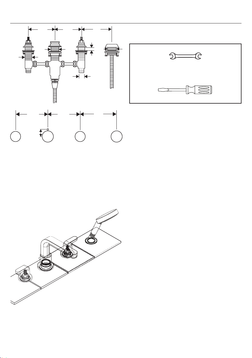
5"
1⅛"
5" 5"
Tools Required / Outiles Utiles /
Herramientas Útiles
1⁵⁄₁₆"
½"
5"
1¼" 1¼"
⅞"
5" 5"
³⁄₁₆"
1½"
not to scale
cold
froid
frío
1⅜"
max 1½"
1½"
27 mm
To insure correct operation of the faucet,
install the hot supply on the left and the
cold supply on the right.
hot
chaud
caliente
Installez la valve de l’eau chaude à gauche
et celle de l’eau froide à droite.
Para que el grifo funcione correctamente,
el suministro de agua caliente debe estar a
la izquierda y el de agua fría a la derecha.
5
Page 6

Installation / Installation / Instalación
1 2
1
2
English Français Español
Install the mounting rings, friction
washers, and fiber washers on the
valves.
Install the mounting nut and washer on the spout tee.
If the mounting surface
is thin, install the white
plastic spacer on the
spout tee. If not, omit
the spacer.
Installez les anneaux de montage,
les rondelles de friction et les rondelles en fibre sur les valves.
Installez l’écrou de montage et
la rondelle sur le raccord en T du
bec.
Si la surface de montage
est mince, installez la
pièce d’espacement en
plastique blanc. Sinon,
vous n’avez pas à
l’installer.
Instale los aros de montaje, las
arandelas de fricción y las arandelas de fibra en las válvulas.
Instale la tuerca de montaje y la
arandela en la “T” del surtidor.
Si la superficie de mon-
taje es delgada, instale
el separador plástico
blanco. De lo contrario,
se puede omitir.
Connect the valves and diverter
housing using the copper tubes
and ⅜” compression fittings.
6
Raccordez les valves au raccord
en T du bec en utilisant les tubes
de cuivre et les raccords à compression de ⅜ po.
Conecte las válvulas a la “T” del
surtidor con tubos de sobre y
accesorios de compresión de ⅜”.
Page 7

3 4
English Français Español
Place the valves and spout tee on
the mounting surface.
Install the stop rings and mounting
rings on the valves.
The stop rings will stop the mounting rings at the correct mounting
height.
Install the sealing ring and spout
adapter on the diverter housing.
Rest the assembly on the mounting
surface, with the spout adapter pin
inserted in its hole.
Poussez le raccord en T du bec et
les valves vers le haut au travers
de la surface de montage.
Installez les bagues de retenue et
les adaptateurs d’écusson sur les
valves.
Les bagues de retenue maintiendront les adaptateurs à la bonne
hauteur pour le montage.
Installez l’anneau d’étanchéité et
l’adaptateur de bec sur le raccord
en T du bec.
Déposez l’assemblage de la valve
sur la surface de montage.
Empuje la “T” del surtidor y las
válvulas hacia arriba a través de
la superficie de montaje.
Instale el aro de sellado y el
adaptador del surtidor en la “T”
del surtidor.
Instale los aros de tope en las
válvulas.
Instale los adaptadores del escudo en las válvulas. Los aros de
tope detendrán los adaptadores a
la altura de montaje correcta.
Apoye la válvula sobre la superficie de montaje.
7
Page 8

5 6
1
2
English Français Español
1
2
Tighten the mounting nuts and
tensioning screws.
Connect the handshower hose to
the spout tee.
8
Serrez les anneaux de montage à
la main. Serrez les vis.
Installez le tuyau. Instale la manguera.
Apriete los aros de montaje con la
mano. Apriete los tornillos.
Page 9

7 8
1
2
English Français Español
Place the handshower holder
and sealing ring on the mounting
surface.
Install the friction washer, metal
washer and mounting nut.
Tighten the tensioning screws.
Push the hose through the handshower holder.
Snap the two halves of the insert
around the hose.
Déposez le support de douchette
sur la surface de montage.
Installez le rondelle en fribre, le
rondelle de friction, et l’anneau de
montage.
Serrez les vis de pression.
Poussez le tuyau vers le haut au
travers de le support douchette.
Installez le mandrin.
Apoye el soporte para la
teleducha sobre la superficie de
montaje.
Instale el aro de montaje, la
arandela de fricción y la arandela
de fibra.
Apriete los tornillos tensores.
Empuje la tuyau arriba a través de
la superficie de montaje.
Instale el inserción.
9
Page 10

9
12
27 mm
English Français Español
If the trim is not to be installed
immediately, install the spout tee
plug and the plaster shields.
Install the hot and cold supply
lines (not included).
10
Installez le bouchon.
Installez les protecteurs.
Installez les conduites d’alimentation d’eau chaude et d’eau froide
(pas d’inclus).
Instale el tapón.
Instale los protectores de yeso.
Instale las tuberías de suministro de agua caliente y fría (no
incluidos).
Page 11

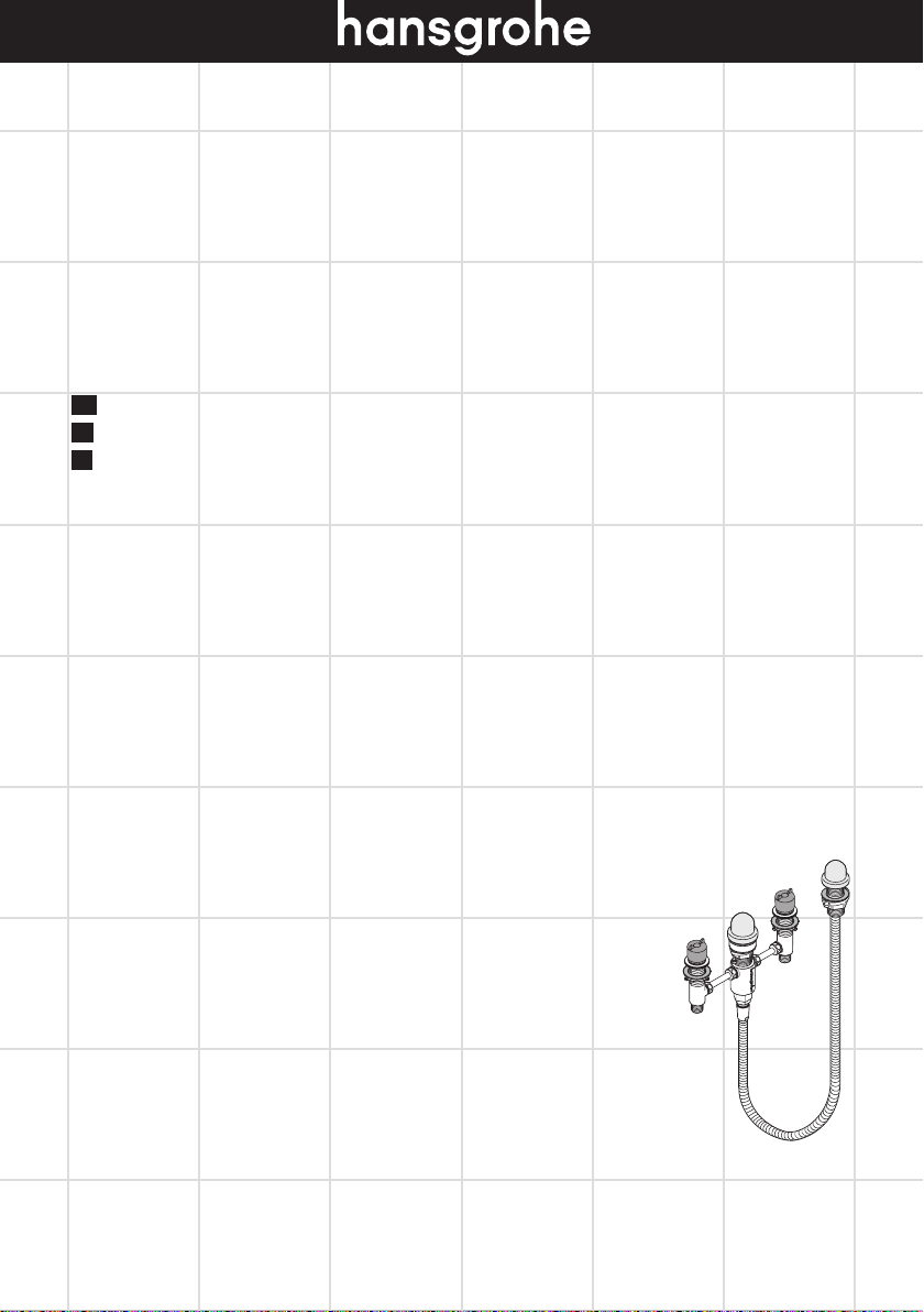
Replacement Parts / Pièces détachées / Repuestos
96942000
88503000
88511000
94009000
96080000
94008000
97568000
13961000
88513000
97161000
11
Page 12

Limited Consumer Warranty
This warranty is limited to products manufactured by Hansgrohe, Inc. (“Hansgrohe”) that are purchased by a consumer in the
United States or Canada after March 1, 1996, and installed in either the United States or in Canada.
WHO IS COVERED BY THE WARRANTY
This limited warranty extends to the original purchaser only. This warranty is non-transferable. Hansgrohe neither assumes nor
authorizes any person to create for it any other obligation or liability in connection with this product.
LENGTH OF WARRANTY
If you are a consumer who purchased the product for use primarily for personal, family or household purposes, this limited
warranty starts on the date of purchase and extends for as long as you own the product and the home in which the product
is originally installed. If you purchased the product for use primarily for any other purpose, including, without limitation, a
commercial purpose, this limited warranty starts on the date of purchase and extends (i) for 1 year, with respect to Hansgrohe
and Commercial products, and (ii) for 5 years, with respect to Axor products. The Rubbed Bronze finish is subject to a 3-year
limited warranty starting on the date of purchase.
WHAT IS COVERED BY THE WARRANTY
This limited warranty covers only your Hansgrohe manufactured product. Hansgrohe warrants this product against defects in
material or workmanship as follows:
Hansgrohe will replace at no charge for parts only or, at its option, replace any product or part of the product that proves
defective because of improper workmanship and/or material, under normal installation, use, service and maintenance. If
Hansgrohe is unable to provide a replacement and repair is not practical or cannot be made in timely fashion, Hansgrohe
may elect to refund the purchase price in exchange for the return of the product. REPAIR OR REPLACEMENT (OR, IN
LIMITED CIRCUMSTANCES, REFUND OF THE PURCHASE PRICE) AS PROVIDED UNDER THIS LIMITED WARRANTY
IS THE EXCLUSIVE REMEDY OF THE PURCHASER.
WHAT IS NOT COVERED BY THE WARRANTY
A. Conditions, malfunctions or damage not resulting from defects in material or workmanship.
B. Conditions, malfunctions or damage resulting from (1) normal wear and tear, improper installation, improper maintenance,
misuse, abuse, negligence, accident or alteration; (2) the use of abrasive or caustic cleaning agents or “no-rinse” cleaning
products, or the use of the product in any manner contrary to the product instructions; or (3) conditions in the home such
as excessive water pressure or corrosion.
C. Labor and other expenses for disconnection, deinstallation, or return of the product for warranty service (including but
not limited to proper packaging and shipping costs), or for installation or reinstallation of the product.
D. Accessories, connected materials and products, or related products not manufactured by Hansgrohe.
E. Any Hansgrohe or Axor product sold for display purposes.
HANSGROHE SHALL NOT BE LIABLE TO PURCHASER OR ANY OTHER PERSON FOR ANY INCIDENTAL, SPECIAL
OR CONSEQUENTIAL DAMAGES, ARISING OUT OF BREACH OF THIS LIMITED WARRANTY.
Some provinces and some states do not allow the exclusion or limitation of incidental or consequential damages, so the above
limitation or exclusion may not apply to you.
TO OBTAIN WARRANTY PARTS OR INFORMATION
Contact your Hansgrohe retailer, or contact Technical Service at:
Hansgrohe, Inc.
1492 Bluegrass Lakes Parkway
Alpharetta, GA 30004
Toll-free 800-334-0455
In requesting warranty service, you will need to provide:
1. The sales receipt or other evidence of the date and place of purchase.
2. A description of the problem.
3. Delivery of the product or the defective part, postage prepaid and carefully packed and insured, to:
12
Page 13

Hansgrohe, Inc.
1492 Bluegrass Lakes Parkway
Alpharetta, GA 30004
Toll-free 800-334-0455
When warranty service is completed, any repaired or replacement product or part will be returned to you postage prepaid.
REVISED MAY 1, 2016.
PRODUCT INSTRUCTIONS AND QUESTIONS
Upon purchase or prior to installation, please carefully inspect your Hansgrohe product for any damage or visible defect.
Prior to installing, always carefully study the enclosed instructions on the proper installation and the care and maintenance of
this product. If you have questions at any time about the use, installation or performance of your Hansgrohe product, or this
warranty, please write us or call us toll-free at 800-334-0455.
13
Page 14

141516
Page 15

Page 16

Hansgrohe, Inc. 1490 Bluegrass Lakes Parkway Alpharetta, GA 30004
Tel. 800-334-0455 Fax 770-889-1783
www.hansgrohe-usa.com
US - Installation Instructions • Part No. 90503001 • Revised 02/2017
 Loading...