

Hansgrohe 06631000, 06575000, 06571000, 06631820, 06575820 Installation Instructions / Warranty
...Page 1
Solaris E
06631XX0
Stratos E
06575XX0
Metro E
06571XX0
Installation Instructions / Warranty
Page 2
2
Installation Considerations
For best results, Hansgrohe recommends that this unit be installed by a licensed, professional plumber.
Please read over these instructions thoroughly before beginning installation. Make sure
that you have all tools and supplies needed to complete the installation.
The high temperature limit stop may be reset, if desired.
•
•
•
Technical Information
Recommended water pressure 14.7 - 72.5 psi
Recommended hot water temp. 120� - 140� F*
Max. hot water temp 165�F*
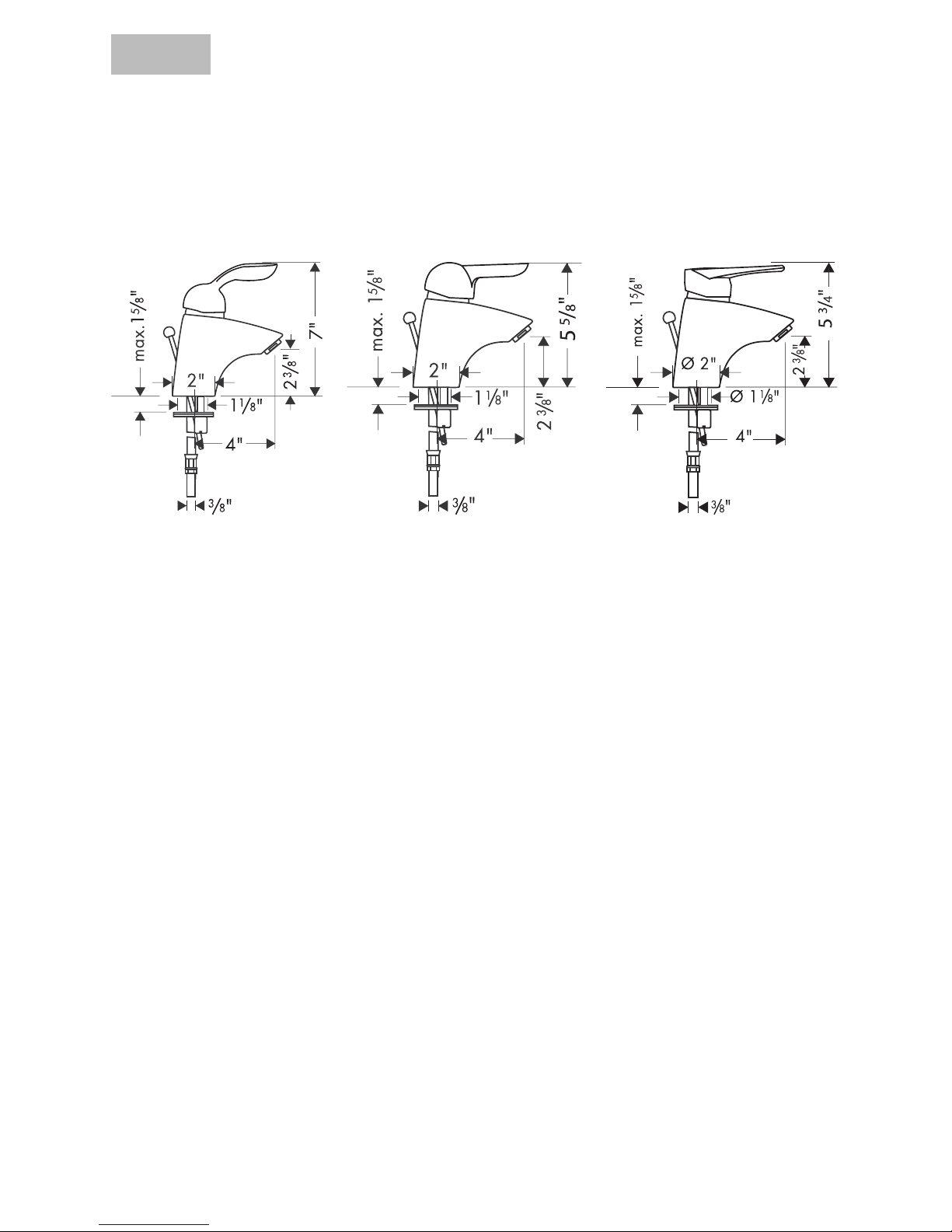
Hole size in mounting surface 1-1/4”
Max. mounting surface depth 1 5/8”
Flow rate 2.2 gpm
M3 Cartridge with high temperature limit stop
3/8” supply hoses - requires 3/8” compression fitting (not included)
Listed by IAPMO
Approved for use in Massachusetts
*Please know and follow all applicable local plumbing codes when setting the temperature on the water heater. In
Massachusetts, the water heater may be set no higher than 112oF.
Solaris E
06631XX0
Stratos E
06575XX0
Metro E
06571XX0
Single Control Lavatory Faucet
Solaris E 06631XX0
Stratos E 06575XX0
Metro E 06571XX0
English
Page 3
3
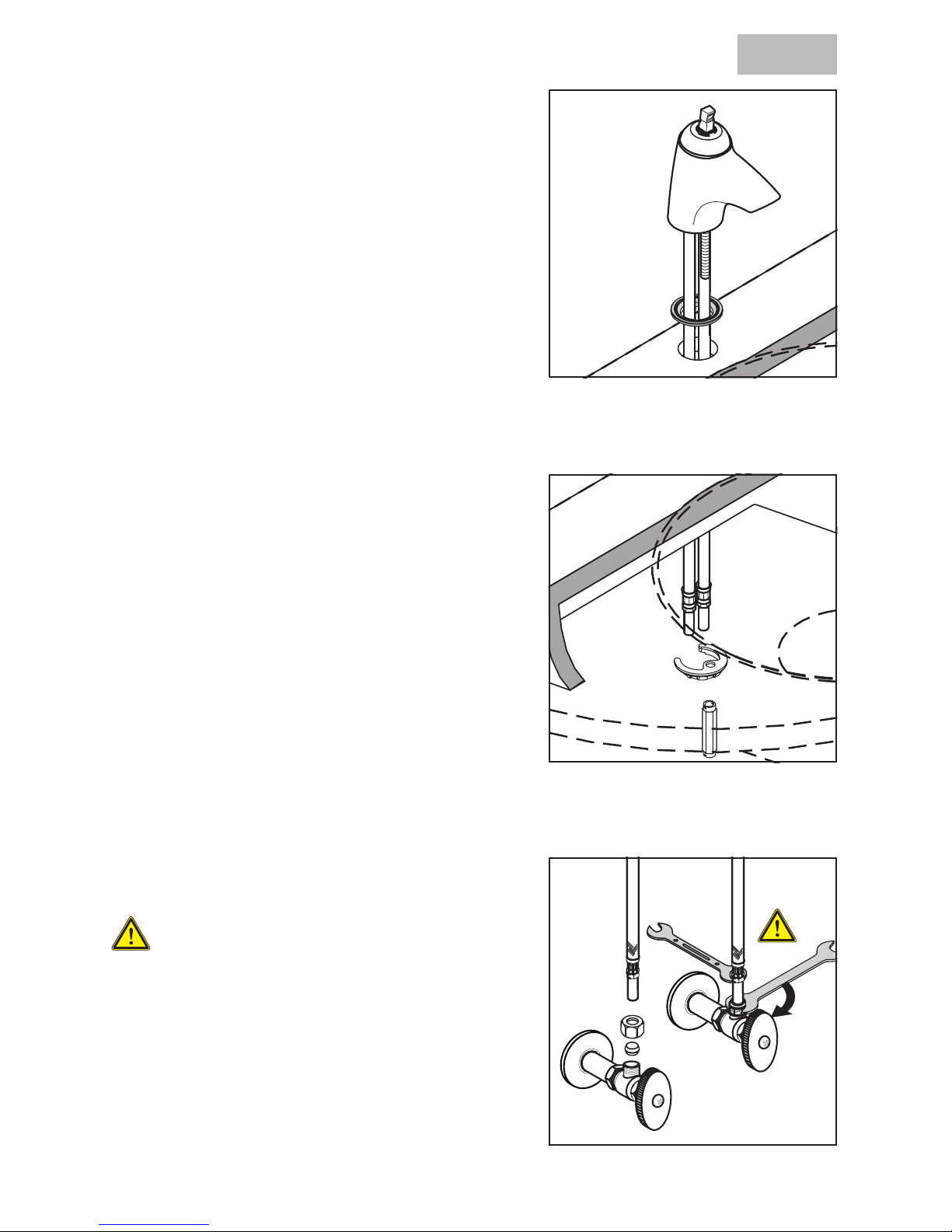
Installation
Place the faucet and sealing gasket on the mounting surface.
Slide the washer over the bolt. Install the collar.
Tighten the collar with a flat head screwdriver.
Secure the supply hoses to the stops with 3/8”
compression fittings (not included).
Use two wrenches, as shown, to keep the
hoses from twisting.
English
Page 4
4
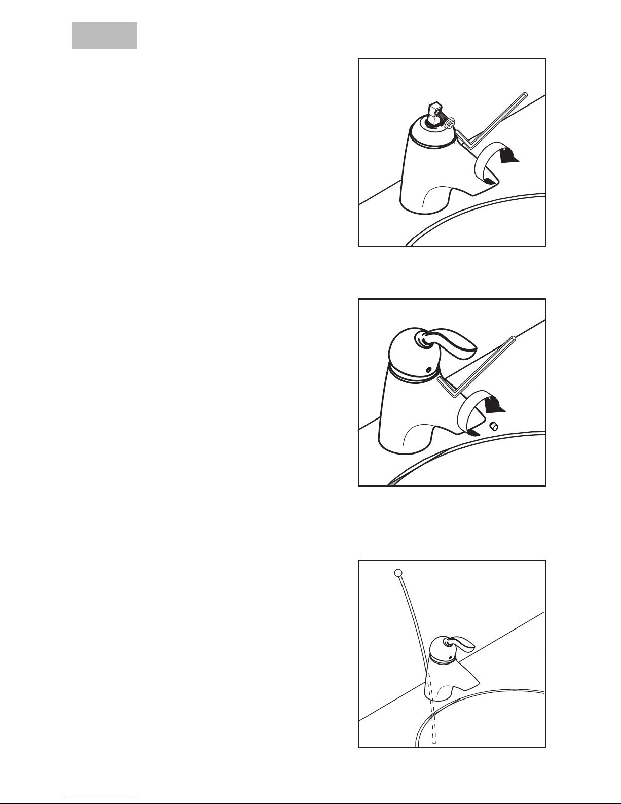
Install the handle screw on the cartridge stem.
Use a 4 mm Allen wrench to tighten it 4 complete
turns.
Push the handle into place over the screw and
the stem.
Use a 4 mm Allen wrench to finish tightening the
screw.
Install the screw cover.
Install the pull rod.
Install the pop-up drain.
Reset the high temperature limit stop (optional).
English
4X
Page 5
5
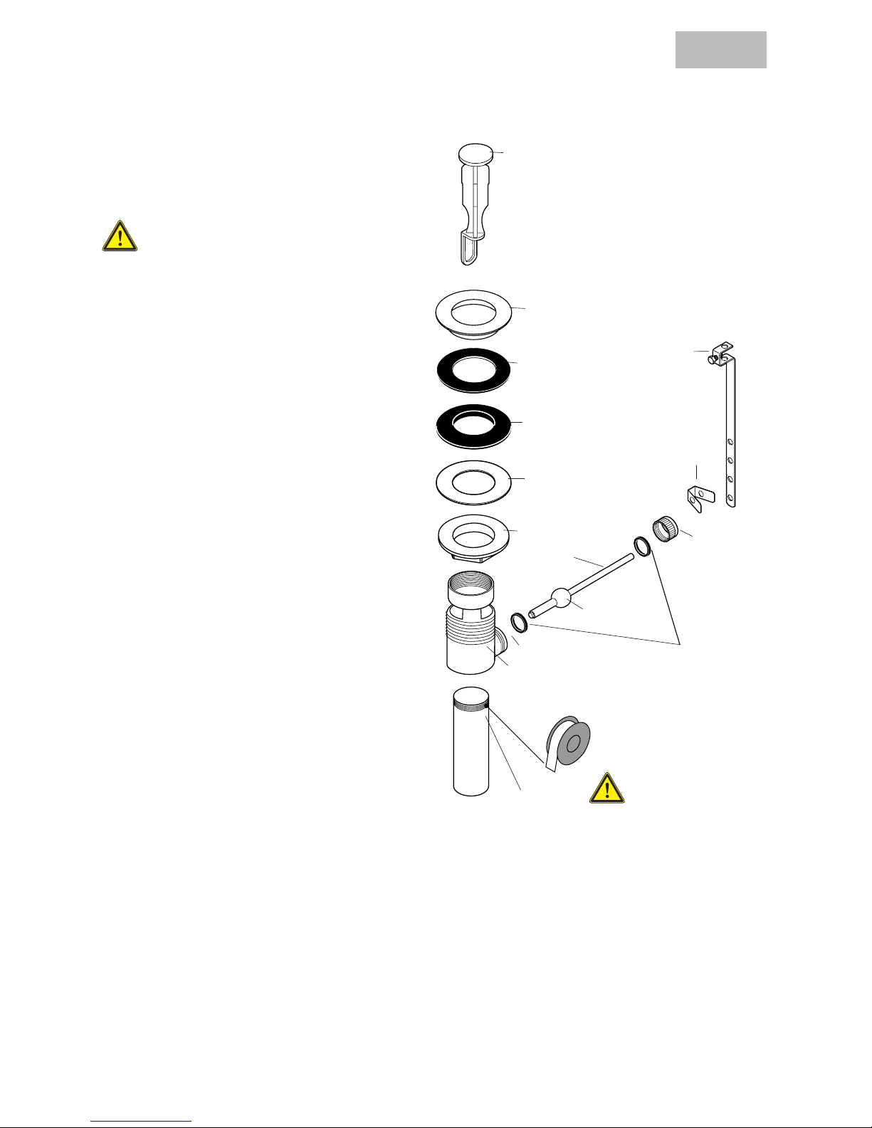
Install the pop-up drain
Remove the plunger assembly.
Unscrew the drain outlet flange from the
tee.
Unscrew the tailpiece from the tee.
Wrap the threads with Teflon tape
and replace.
Install the flexible sealing gasket on the
flange. Sit it in the sink outlet.
From below, install the black mack gasket,
white friction ring, and retainer nut to the
flange. Do not tighten the nut against the
bottom of the sink at this time.
Thread the tee and tailpiece to the flange.
The pivot must face the faucet. If necessary, turn the drain assembly.
Tighten the retainer nut.
Sit the plunger assembly in the drain.
Install the horizontal rod through the pivot
ball seals and into the tee so that the end
goes through the loop in the bottom of the
height adjuster. The two pivot ball seals
should surround the pivot ball.
Slide the link over end of pull rod. Tighten
screw.
Slide one end of spring clip over end of
horizontal rod. Slide link over end of horizontal rod. Test motion of drain plunger.
Reposition link as necessary. There are
multiple holes in the link -- the horizontal
rod may go through any of the holes.
When satisfied with the action of the drain,
slide the other end of the spring clip over
the end of the horizontal rod.
English
plunger
flange
tailpiece
sealing gasket
mack gasket
friction ring
retainer nut
tee
pivot
horizontal
rod
pivot ball
pivot ball
seals
spring
clip
link
nut
Page 6

6
Reset the High Temperature Limit Stop (optional)
Use a 4 mm Allen wrench to push the screw
cover into the handle
Use the 4mm Allen wrench to loosen the handle
screw 4 complete revolutions. Remove the
handle.
Remove the nut cover.
Remove the handle screw from the stem of the
cartridge.
Remove the high temperature limit stop.
Replace the nut cover. Replace the handle
screw. Use the Allen wrench to turn the screw 4
revolutions.
Replace the handle. Finish tightening the handle
screw. Turn on the water and test the faucet.
Replace the high temperature limit stop so that the
pin on the cartridge is in the desired slot on the
limit stop. Note: the temperatures given in the
diagram assume a water heater temperature of
140° F, a cold water temperature of 50° F and a
water pressure of 45 PSI.
English
Page 7

7
Mitigeurs de lavabo
Solaris E 06631XX0
Stratos E 06575XX0
Metro E 06571XX0
Solaris E
06631XX0
Stratos E
06575XX0
Metro E
06571XX0
Données techniques
Pression d’eau recommandée 22 -72 psi
Température recommandée pour l’eau chaude 120° – 140°F *
Dimension du trou dans la surface de montage 1 1/4 po
Épaisseur maximale de la surface de montage 1 5/8 po
Débit 2,2 gpm max.
Accrédité par IAPMO
* Vous devez connaître et respecter tous les codes de plomberie locaux applicables pour le réglage de la température
du chauffe-eau. Dans le Massachusetts, la température d’un chauffe-eau ne doit pas excéder 112°F.
À prendre en considération pour l’installation
Les tuyaux d’arrivée flexibles requièrent des butées d’arrêt avec des raccords à compression de 3/8 po (non compris).
Le robinet comprend la butée limite d’eau chaude en position maximum. Ce réglage
peut être modifié si désiré.
Pour obtenir les meilleurs résultats, Hansgrohe recommande de confier l’installation à un
plombier professionnel certifié.
•
•
•
Français
Page 8

8
Installation
Placez le robinet et le joint d’étanchéité sur la
surface de montage.
Installez la rondelle et le collier de montage.
Serrez le collier de montage.
Installez les tuyaux d’arrivée flexibles sur les butées d’arrêt avec des raccords à compression de
3/8 po (non compris).
Utilisez deux clés, tel qu’illustré dans le
schéma, pour éviter que les tuyaux ne
s’entortillent.
Français
Page 9

9
Installation de la poignée
Installez la vis de la poignée sur la tige de la
cartouche. Serrez 4 tours complets.
Poussez la poignée en place sur la vis et la
tige.
Serrez la vis à l’aide d’une clé hexagonale de
4 mm.
Installez le cache-vis.
Installez le tirette.
Installez l’obturateur à clapet.
Reprogrammez la butée limite d’eau chaude (en
option).
Français
4X
Page 10

10
Installation de l’obturateur à
clapet
Retirez le plongeur.
Dévissez la collerette du raccord en T.
Dévissez la queue du raccord en T.
Enrobez les filets de ruban de plomberie Téflon et remettez en place.
Installez le joint d’étanchéité sur la collerette. Installez-les dans l’évier.
Par le dessous, installez le joint mack,
l’anneau de friction et l’écrou de retenue
sur la collerette. Ne serrez pas complètement l’écrou.
Installez le raccord en T et la queue. Au
besoin, tournez l’obturateur de façon à ce
que le pivot soit face au robinet.
Serrez l’écrou de retenue.
Mettez le plongeur dans l’obturateur.
Installez les joints sphériques sur la tige
horizontale, un de chaque côté de l’écrou
sphérique. Poussez la tige horizontale
dans le pivot. Serrez l’écrou.
Faites glisser la tringle sur l’extrémité de la
tige d’entraînement. Serrez la vis.
Glissez la tringle sur la tige horizontale. Vérifiez le mouvement de la tige
d’entraînement et du butoir. Repositionnez
la tringle si nécessaire. La tringle comporte
plusieurs ouvertures – la tige horizontale
peut être insérée dans l’une d’entre elle au
choix.
Si le mouvement de l’obturateur semble
adéquat, faites glisser la pince à ressort sur
l’extrémité de la tige horizontale.
Français
plongeur
collerette
queue
joint d’étanchéité
joint mack
anneau de
friction
écrou de
retenue
T
pivot
tige horizontale
pivot
joint spherique
tringle
écrou
pince
Page 11

11
Réglage de la butée limite d’eau chaude (en option)
Poussez le cache-vis dans la poignée à l’aide
d’une clé hexagonale de 4 mm.
Desserrez la vis de la poignée (4 tours complets).
Enlevez la poignée et retirez le cache-vis.
Enlevez le cache-écrou.
Retirez la vis de la poignée.
Enlevez la butée limite d’eau chaude.
Remettez en place la butée limite d’eau chaude
de sorte que l’onglet de la cartouche soit dans
la fente voulue de la butée. Les températures
indiquées sur le schéma présupposent que la température du chauffe-eau est réglée à 140° F pour
l’eau chaude et à 50° F pour l’eau froide, à raison
d’une pression d’arrivée d’eau de 45 psi.
Remettez le cache-écrou en place. Réinstallez la
vis de la poignée. Serrez la vis (4 tours complets).
Remettez la poignée en place. Serrez la vis.
Installez le cache-vis. Ouvrez l’eau et vérifiez le
robinet.
Français
Page 12

12
Replacement Parts
1 nut cover 94192XX0
2 nut 94194000
3 cartridge 92730000
4 fixing set 96016000
5 aerator 13085XX0
6 pull rod and knob 88541XX0
7 handle - Solaris 06840XX0
handle - Stratos 06842XX0
handle - Metro 06843XX0
8 screw cover 88655000
pop-up drain 88509XX0
XX = color
00 = chrome
82 = brushed nickel
83 = polished nickel
1
2
3
4
5
6
7
8
Page 13

13
Cleaning Recommendation for Hansgrohe Products
Modern lavatory faucets, kitchen faucets, and showers consist of very different materials to comply with the needs of
the market with regard to design and functionality. To avoid damage and returns, it is necessary to consider certain
criteria when cleaning.
Cleaning Materials for Faucets and Showers
Acids are a necessary ingredient of cleaning materials for removing lime, however please pay attention to the following points when cleaning faucets and showers:
Only use cleaning materials which are explicitly intended for this type of application.
Never use cleaning materials which contain hydrochloric, formic, phosphoric, or acetic acid, as they cause
considerable damage.
Never mix one cleaning material with another.
Never use cleaning materials or appliances with an abrasive effect, such as unsuitable cleaning powders, sponge
pads, or micro fiber cloths.
Cleaning Instructions for Faucets and Showers
Please follow the cleaning material manufacturer’s instructions. In addition, pay attention to the following points:
Clean the faucets and showers as and when required
Use the amount of cleaning product and the amount of time recommended by the manufacturer. Do not leave the
cleaner on the fixture longer than necessary.
Regular cleaning can prevent calcification.
When using spray cleaners, spray first onto a soft cloth or sponge. Never spray directly onto the faucet as droplets can enter openings and gaps and cause damage.
After cleaning, rinse thoroughly with clean water to remove any cleaner residue.
Important
Residues of liquid soaps, shampoos, and shower foams can also cause damage, so rinse with clean water after using.
Please note: if the surface is already damaged, the effect of cleaning materials will cause further damage.
Components with damaged surfaces must be replaced or injury could result.
Damage caused by improper treatment is not covered under the warranty.
•
•
•
•
•
•
•
•
•
Recommandations pour le nettoyage des produits Hansgrohe
Les robinetteries modernes de lavabo, de cuisine et de douche utilisent des matériaux très différents pour répondre aux
besoins du marché en termes de conception et de fonctionnalité. Certaines règles de base doivent être respectées lors Certaines règles de base doivent être respectées lorsCertaines règles de base doivent être respectées lors
du nettoyage de ces produits afin d’éviter de les endommager ou d’avoir à les retourner.
Produits de nettoyage pour robinetteries et douches
Les acides sont une partie intégrante nécessaire de tous les produits de détartrage; il faut cependant prendre les
précautions suivantes lors du nettoyage des robinets et des douches :
N’utilisez que des produits/articles de nettoyage conçus spécifiquement pour les articles de robinetterie et de
douche.
N’utilisez jamais de produits/articles de nettoyage contenant de l’acide chlorhydrique, formique, phosphorique
ou acétique car ils pourraient causer des dommages considérables.
Ne mélangez jamais deux produits de nettoyage.
N’utilisez jamais de produits/articles de nettoyage de nature abrasive tels que poudres de nettoyage, tampons-
éponge ou chiffons microfibre non appropriés.
•
•
•
•
Page 14

14
Limited Lifetime Consumer Warranty
This product has been manufactured and tested to the highest quality standards by Hansgrohe, Inc. (“Hansgrohe”).
This warranty is limited to Hansgrohe products which are purchased by a consumer in the United States after March 1,
1996, and installed in either the United States or Canada.
WHO IS COVERED BY THE WARRANTY
This warranty extends to the original consumer purchaser only. This warranty is non-transferable.
WHAT IS COVERED BY THE WARRANTY
This warranty covers only your Hansgrohe manufactured product. Hansgrohe warrants this product against defects in
material or workmanship as follows: Hansgrohe will repair at no charge for parts only or, at its option, replace any
product or part of the product that proves defective because of improper workmanship and/or material, under normal
installation, use, service and maintenance. If Hansgrohe is unable to provide a replacement and repair is not practical
or cannot be timely made, Hansgrohe may elect to refund the purchase price in exchange for the return of the product.
LENGTH OF WARRANTY
Replacement or repaired parts of products will be covered for the term of this warranty as stated in the following two
sentences. If you are a consumer who purchased the product for use primarily for personal, family, or household
purposes, this warranty extends for as long as you own the product and the home in which the product is originally
installed. If you purchased the product for use primarily for any other purpose, including, without limitation, a commercial purpose, this warranty extends only (i) for 1 year, with respect to Hansgrohe and Commercial products, and (ii) for
5 years, with respect to AXOR products.
THIS WARRANTY DOES NOT COVER, AND HANSGROHE WILL NOT PAY FOR:
A. Conditions, malfunctions or damage not resulting from defects in material or workmanship.
B. Conditions, malfunctions or damage resulting from (1) normal wear and tear, improper installation, improper
maintenance, misuse, abuse, negligence, accident or alteration, or (2) the use of abrasive or caustic cleaning
agents or “no-rinse” cleaning products, or the use of the product in any manner contrary to the product instructions. (3) Conditions in the home such as excessive water pressure or corrosion.
C. Labor or other expenses for the disconnection, deinstallation, or return of the product for warranty service, or for
installation or reinstallation of the product (including but not limited to proper packaging and shipping costs), or
for installation or reinstallation of the product.
Instructions de nettoyage pour robinetteries et douches
Veuillez suivre les instructions du fabricant de produits/articles de nettoyage. De plus, tenez compte des conseils De plus, tenez compte des conseilsDe plus, tenez compte des conseils
suivants :
Nettoyez vos produits de robinetterie et de douche aussi souvent que nécessaire.
Utilisez la quantité de produit nettoyant et respectez la durée recommandée par le fabricant. Ne laissez pas le Ne laissez pas leNe laissez pas le
produit sur les articles de robinetterie plus longtemps que nécessaire.
Un nettoyage régulier peut prévenir la formation de dépôts calcaires.
Si vous utilisez des nettoyants en vaporisateur, vaporisez d’abord sur une éponge ou un chiffon. Ne vaporisez Ne vaporisezNe vaporisez
jamais directement sur un robinet : des gouttelettes pourraient s’infiltrer dans les ouvertures et les interstices et
endommager celui-ci.
Après le nettoyage, rincez abondamment avec de l’eau propre pour éliminer tout résidu de produit nettoyant.
Important
Les résidus de savon liquide, de shampoing et de mousse pour la douche peuvent également endommager la robinetterie; rincez donc avec de l’eau propre après utilisation de ces produits.
Veuillez noter : si la surface est déjà endommagée, les produits de nettoyage l’endommageront encore plus.si la surface est déjà endommagée, les produits de nettoyage l’endommageront encore plus.
Les composants dont la surface est endommagée devraient être remplacés sous peine d’entraîner
des blessures.
Les dommages dus à un mauvais traitement ne sont pas couverts par la garantie.
•
•
•
•
Page 15

15
D. Accessories, connected materials and products, or related products not manufactured by Hansgrohe.
TO OBTAIN WARRANTY PARTS OR INFORMATION
Contact your Hansgrohe retailer, or contact Technical Service at:
Hansgrohe Inc.
1492 Bluegrass Lakes Parkway
Alpharetta GA 30004
Toll-free (800) 334-0455.
In requesting warranty service, you will need to provide
1. The sales receipt or other evidence of the date and place of purchase.
2. A description of the problem.
3. Delivery of the product or the defective part, postage prepaid and carefully packed and insured, to Hansgrohe
Inc. 1492 Bluegrass Lakes Parkway, Alpharetta, Georgia 30004, Attention: Technical Service, if required by
Hansgrohe.
When warranty service is completed, any repaired or replacement product or part will be returned to you postage
prepaid.
EXCLUSIONS AND LIMITATIONS
REPAIR OR REPLACEMENT (OR, IN LIMITED CIRCUMSTANCES, REFUND OF THE PURCHASE PRICE) AS PROVIDED
UNDER THIS WARRANTY IS THE EXCLUSIVE REMEDY OF THE PURCHASER. HANSGROHE NEITHER ASSUMES
NOR AUTHORIZES ANY PERSON TO CREATE FOR IT ANY OBLIGATION OR LIABILITY IN CONNECTION WITH
THIS PRODUCT.
HANSGROHE SHALL NOT BE LIABLE TO PURCHASER OR ANY PERSON FOR ANY INCIDENTAL, SPECIAL, OR
CONSEQUENTIAL DAMAGES, ARISING OUT OF BREACH OF THIS WARRANTY OR ANY IMPLIED WARRANTY
(INCLUDING MERCHANTABILITY).
Some States do not allow the exclusion or limitation of incidental or consequential damages, so the above limitation
or exclusion may not apply to you. This warranty gives you specific legal rights, and you may have other rights which
vary from State to State. You may be required by law to give us a reasonable opportunity to correct or cure any failure
to comply before you can bring any action in court against us under the Magnuson-Moss Warranty Act.
PRODUCT INSTRUCTIONS AND QUESTIONS
Upon purchase or prior to installation, please carefully inspect your Hansgrohe product for any damage or visible
defect. Prior to installing, always carefully study the enclosed instructions on the proper installation and the care and
maintenance of the product. If you have questions at any time about the use, installation, or performance of your
Hansgrohe product, or this warranty, please call or write to us or call us toll-free at 800 334 0455.
Page 16

Hansgrohe, Inc. • 1490 Bluegrass Lakes Parkway • Alpharetta, GA 30004
Tel. 770-360-9880 • Fax 770-360-9887
www.hansgrohe-usa.com
US - Installation Instructions • Part No. 90964401-07 • Revised 02/2008
 Loading...