

Hansen HS7 Specifications, Applications, Service Instructions & Parts
HS7 Solenoid Valve
Bulletin S121c
APR 2006
Specifications, Applications,
Service Instructions & Parts
HS7
SOLENOID VALVE
3/4”, 1”, 1-1/4” PORT
(20, 25, 32 mm)
Flanged
3/4” thru 1 1/4”
FPT, SW, WN, ODS
for refrigerants
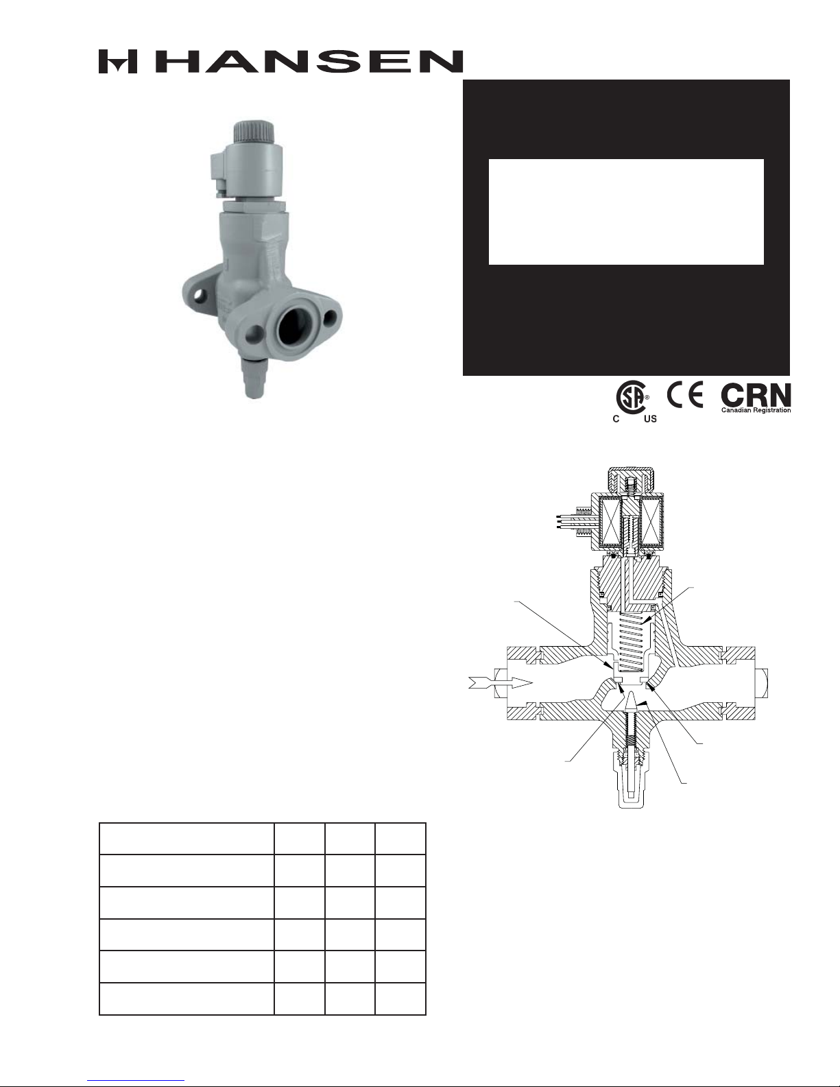
INTRODUCTION
This flanged, heavy duty, pilot-operated, industrial
refrigeration solenoid valve controls the flow of
refrigerant. When electrically energized, a slight
pr ess ure differe nce across the va lve c auses it to open
wide; when de-energized, a spring promptly closes the
ma in Teflon se at to stop a ll flow in the ar row directi on
on the valve body.
APPLICATIONS
This advanced design valve is ideal as a standard,
stock, ammonia liquid line solenoid valve. While
primarily for ammonia, this valve is also suitable for
R22, R134a, CO2 and other approved refrigerants.
Most common use is to automatically stop liquid line
feed to recirculating liquid overfeed evaporators, to
float switch controlled accumulators, and to thermal
expansion valves; it is also suitable for hot gas defrost,
and evaporator suction. (Note: for gravity liquid drain
or equalization applications use low pressure drop
HCK2 gas-powered suction stop valve or HS9B gaspowered solenoid valve.)
MAXIMUM RATINGS, AMMONIA†
PORT SIZE 3/4”
Liquid, Receiver Pressure
Tons (kW), .2 bar Δ P
Recirculation, 4 to 1
Tons (kW), .2 bar Δ P
Hot Gas, for 0ºF
Ton s (k W)
Suction, 2 psi drop at 20ºF
Tons (kW), .15 drop at -7ºC
Flow Factor
Cv (Kv)
(20mm)1”(25mm)
200
(765)
45
(228)63(293)90(455)
21
(73)
12
(42)
8.0
(7.0)
263
(983)
27
(94)40(140)
16
(56)
10.5
(9.0)
† For flow near maximum ratings, piping should be
one size larger than port.
1 1/4”
(32mm)
400
(1530)
24
(84)
16.3
(14)
KEY FEATURES
STAINLESS
STEEL
PISTON
TEFLON DISC
STAINLESS STEEL
CLOSING SPRING
TAP ER ED SEAT
MANUAL OPENING
STEM
ADDITIONAL FEATURES
Encapsulated Hansen standard coil
300 psi (20 bar) MOPD, 500 psi (34 bar) for CO2
Teflon main & pilot seats
Manual opening stem
Available close-coupled strainer
Heavy duty, pilot-operation
Vertical or horizontal installation
CSA Certified Status
Non-asbestos gaskets
Wireless pilot lights
CE Available
e.
MATERIAL SPECIFICATIONS
Body: Ductile iron (Nodular Iron GGG-40)
Bonnet-Cartridge: Steel, plated
Piston: Stainless steel
Plunger: Stainless steel
Solenoid Tube: Stainless steel
Pilot Orifice: Stainless steel
Seat: Teflon
Safe Working Pressure: 400 psig (27 bar) 600 psig
(41 bar) for CO2
Operating Temperature: –60ºF to +240ºF
(–50ºC to +115ºC)
ADVANTAGES
Power saving, low-wattage molded coil; Teflon seats;
stainless steel trim including piston; spring-closing;
double seal manual opening stem. One standard
molded coil fits all Hansen valves.
INSTALLATION
Protect interior of valve from dirt during installation;
normally use close-coupled inlet strainer. Allow 2.25”
(57mm) above valve for coil removal, 3” (76 mm) below
strainer for screen removal. Match arrow on body
with system flow direction. If a pressure reversal
can occur, as during hot gas defrost with liquid
recirculation, use a check valve on the outlet side
of the HS7. For proper flange gasket sealing, care
must be taken when threading or welding to assure
flanges are parallel to each other and perpendicular
to pipe. Also, gaskets should be lightly oiled and all
bolts must be tightened evenly.
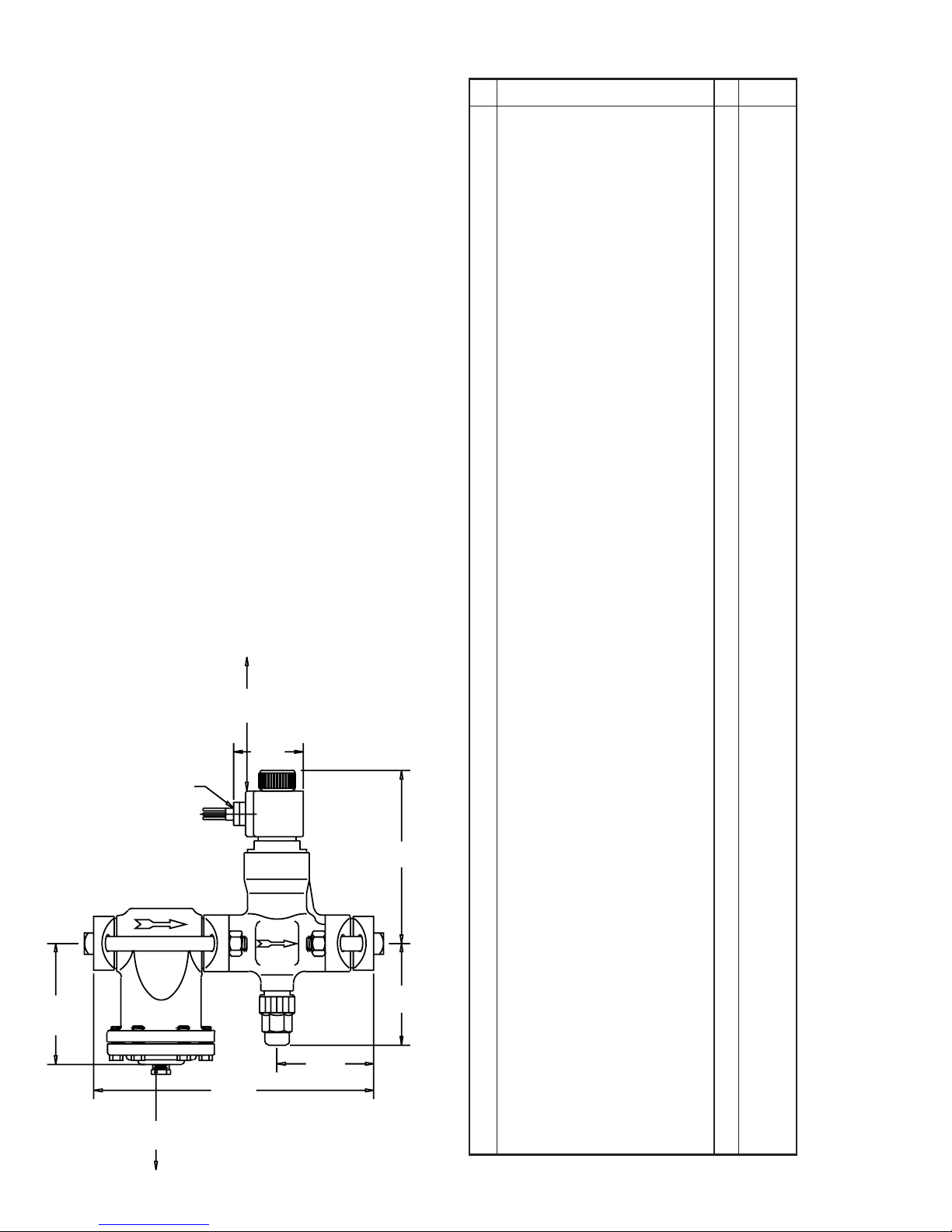
INSTALLATION DIMENSIONS
INCHES (MILLIMETERS)
PARTS LIST
Item Description Qty Part No.
Coil Kit (115V) 1/2" Fitting w/leads 1 70-1085
Coil Kit (208/230V) 1/2" Fitting w/leads 1 70-1086
Coil Kit (24V) 1/2" Fitting w/leads 1 70-1087
Coil Kit (Other Voltages) 1 FACTORY
Above kits consist of:
1a Bare Coil, 115V 50/60 Hz w/leads 1 70-0580
1b Bare Coil, 208/230V 50/60Hz w/leads 1 70-0581
Bare Coil, 24V 50/60Hz w/leads
1c
Other Voltage Coils
1d
Coil Knob
2
O-Ring
3
Solenoid Tube/Plunger Kit 1 70-1059
Above kit consists of:
Plunger
5
Solenoid Tube
6
7 Solenoid Tube Gasket 1 70-0301
8 Tube Screws 4 70-0297
2 Coil Knob 1 70-0579
O-Ring
3
Gasket Kit 1 70-1017
Above kit consists of:
Solenoid Tube Gasket
7
Upper Body O-Ring
9
10 Lower Body O-Ring 1 70-0130
11 Flange Gasket 3 70-0132
12 Stem O-Ring 1 70-0010
13 Stem Washer 1 70-0026
14 Packing Nut 1 70-0019
16 Stem Packing 1 70-0025
15 Seal Cap O-Ring 1 70-0011
Bonnet Cartridge Kit 1 70-1018
Above kit consists of:
17 Cartridge Assembly 1 70-0162
Gasket Kit 1 70-1017
Solenoid Tube/Plunger Kit 1 70-1059
Piston Assembly Kit 3/4" 1 70-1019
Piston Assembly Kit 1" 1 70-1020
1
70-0582
1
FACTORY
1
70-0579
1
75-0340
1
70-0295
1
70-0298
1
75-0340
1 70-0301
1 70-0131
ALLOW 2.25” (57)
FOR COIL REMOVAL
2.95”
(75)
1/2” NPSM
5.10”
(130)
4.10”
11.90 ”
(104)
(302)
ALLOW 3” (76)
8.25” (210) WITHOUT STRAINER
FOR STRAINER BASKET REMOVAL
Maximum width of valve is 4.63” (116).
S121c
APR 2006
7.24 ”
(184)
4.21”
(107)
Piston Assembly Kit 1 1/4" 1 70-1021
Above kits consist of:
18a Piston Assembly 3/4" 1 70-0166
18b Piston Assembly 1" 1 70-0163
18c Piston Assembly 1 1/4" 1 70-0167
19 Closing Spring 1 70-0155
9 Upper Body O-Ring 1 70-0131
10 Lower Body O-Ring 1 70-0130
Stem Kit 1 70-1022
Above kit consists of:
20 Stem 1 70-0128
Gasket Kit 1 70-1017
Seal Cap Kit 1 70-1023
Above kit consists of:
21 Seal Cap 1 50-0411
15 Seal Cap O-Ring 1 70-0011
Bolt and Nut Kit
For HS7 less Strainer (a) 70-1024
For HS7 with Strainer (b) 70-1025
Above kits consist of:
22 Nut 4 70-0136
23a Bolt (less Strainer) 2.75" 4 70-0339
23b Bolt (with Strainer) 2.75" 2 70-0339
23b Bolt (with Strainer) 6.5" 2 70-0134
24 Assembled Body Replacement Kit FACTORY
Complete Valve less Coil Kit and Flanges
25 Flange Kit (FPT,SW,WN,ODS) FACTORY
Includes (2) Flanges only;
Specify Style and Siz
2
 Loading...