

Hansen HS2, HS2F Specifications, Applications, Service Instructions & Parts

HS2 Solenoid Valve
This threaded end industrial refrigeration duty
solenoid valve is very simple and compact but
rugged in construction. Body is plated steel alloy.
The direct lifting stainless steel plunger contains a
Teflon seat which closes on a stainless steel orifice.
When electrically energized, valve opens wide; when
de-energized, flow stops in the direction of the arrow
on the valve body.
APPLICATIONS
This small, direct lifting valve is used primarily as a
pilot for various larger gas-powered or liquid powered
main valves, as a remote pilot for back pressure
regulators or other devices, or as a liquid stop valve
for expansion valves, float valves, or as a general
purpose pilot line for ammonia, R22, R134a, CO2 and
other approved refrigerants or oil.
ADDITIONAL FEATURES
Compact, low cost
Low wattage, Hansen standard coil
300 psi (20 bar) MOPD
Stainless steel seat orifice
Removable solenoid tube
Heavy-duty, direct lift
CSA Certified
Non-asbestos gaskets
Bulletin S114c
SEP 2005
Specifications, Applications,
Service Instructions & Parts
HS2
SOLENOID VALVE
5/32" (4 mm) PORT
Threaded End
1/4" thru 1/2" FPT
(7 mm thru 15 mm)
1/4" thru 3/4" Flanged
(7 mm thru 20 mm)
for refrigerants
KEY FEATURESINTRODUCTION
WATERTIGHT
ENCAPSULATED
COIL
TEFLON DISC
STEEL BODY
MATERIAL SPECIFICATIONS
Body: Steel, plated
Solenoid Tube: Stainless steel
Plunger: Stainless steel
Seat Orifice: Stainless steel
Seat: Teflon
Safe Working Pressure: 400 psig (27 bar),
600 psig (40 bar) available for CO2
Operating Temperature: –60°F to +240°F (–50° to
+115° C)
ADVANTAGES
Power-saving, low-wattage encapsulated coil; Teflon
disc seat; stainless steel trim; spring-closing. One
standard coil fits all Hansen valves. The valve can be
installed in vertical lines.
INSTALLATION, THREADED
CONNECTION
Match the arrow on the body with the system flow
direction. Protect the interior of the valve from dir t
during installation. Check mating pipe threads for
cleanliness and accuracy before installing. Use a
small quantity of pipe dope on pipe threads. Use a
flat jaw wrench on the body close to the pipe, being
careful not to damage the pipe threads with pipe
wrench jaws. Allow 2.25" (57 mm) above the valve
for coil removal.
ELECTRICAL
The coil draws 16 watts and will operate properly
between 85% and 110% of the rated voltage (24V coil
draws 19 watts). Standard coil connection is a 1/2"
fi t t i ng (NPS M ) for c o nduit, w ith two 18" wir e leads p l us
gr o und w ire. Coils with DIN p lug o r 1/2" N PSM q uick
disconnect plug are available. Contact the factory.
All coils are totally encapsulated and meet NEMA 3R
(rainproof) and NEMA 4 (splashproof, approx. IP65)
requirements. The coil should only be energized
while on the solenoid tube. Otherwise, immediate coil
burnout may occur. To avoid bending the solenoid
tube, remove the coil from the valve before connecting
any electrical conduit. Pilot lights are available.
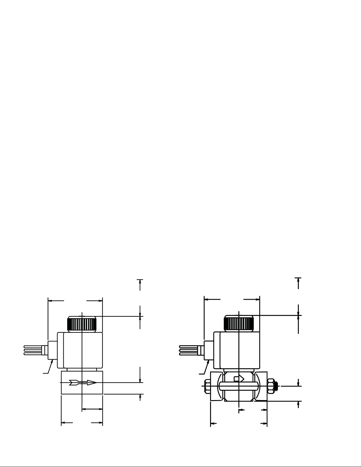
1/2" NPS M
STANDARD
2.95"
(75)
1.13"
(29)
2.25"
(57)
HS2
INSTALLATION DIMENSIONS
INCHES (MM)
ALLOW 2.25" (57)
FOR COIL REMOVAL
3.62"
(92)
3.94"
(100)
WITH PILOT LIGHT
1/2" NPS M
STANDARD
0.63"
(16)
2.95"
(75)
SW, FPT
3.00"
(76)
HS2F
SW, FPT
1.5 0"
(38)
ODS, WN
3.76"
(96)
ALLOW 2.25" (57)
FOR COIL REMOVAL
3.75"
(95)
4.07"
(103)
WITH PILOT LIGHT
0.80"
(20)
ODS, WN
1.8 8"
(48)
S114c
SEP 2005
2
 Loading...