

Hansen HCK4-2, HCK4-4, HCK4-3, HCK4-5, HCK4-8 Specifications, Applications, Service Instructions & Parts
...
HCK4 -4 Check Val ve
Bulletin C401e
JUL 2006
Specifications, Applications,
Service Instructions & Parts
HCK4 IN-LINE CHECK VALVES
5/8” THRU 4” PORT
(16 mm THRU 100 mm)
Flanged
3/8” thru 4”
(10 mm thru 100 mm)
FPT, SW, WN, ODS
for refrigerants
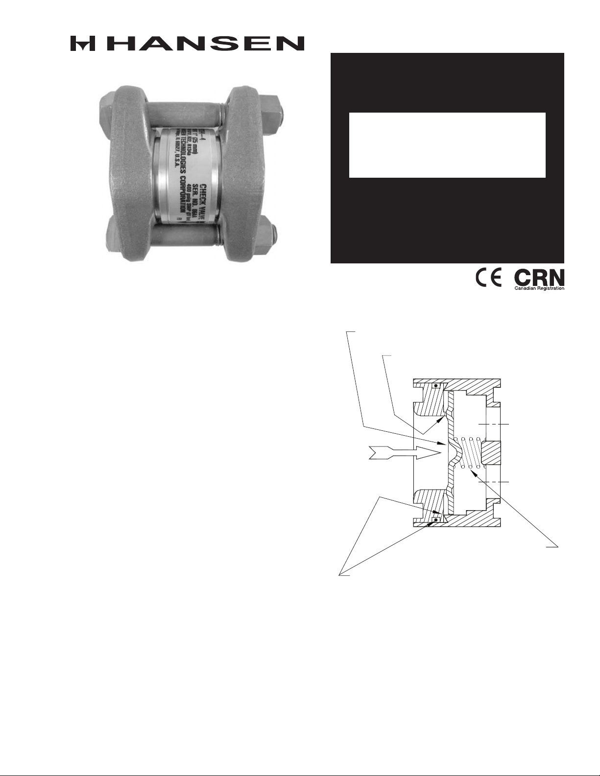
INTRODUCTION
The HC K4 series of dependable, com pac t, rugge d
in-line check valve s (disc type n on- return va lves) is
ideally suited for refr igerant flow control applications.
Valves open wide for flow in the arrow direction on the
valve bo dy. Valves close quickly a nd r eli abl y when
flow r eversals occur.
Plated b odies a nd st ainless steel sea t discs a nd
spring s enable them to withstand expec ted indus trial
refriger ation conditi ons. Fur t her mor e, these check
valves can be mounte d in any position and close-
coupled to other valves .
ADVANTAGES
These compa ct c hec k valves offer reliable op eratio n
regar dless of posit ion. Corrosion resistant stainl ess
steel seat disc. Metal-to-metal seats facilitate durable,
tight clo sing of valves .
APPLICATIONS
These i n-line c hec k valve s are designed to p rovide
refriger ant flow control to hot gas lines, liquid li nes ,
compressor discharg e line s, suction lines , an d hot
ga s heate d drain pans.
Th ese valves are n ot rec omm ende d for use with
pu l s a ting l oads s uch a s low speed c ompressor
discharge and screw compressor side port applications.
For applications suc h as the se, use Han sen HCK1
piston type check valves.
KEY FEATURES
STAIN LESS STEE L SEAT D ISC
LAPPED ME TAL SE ATI NG
CLOS IN G SPRIN G
DUAL BODY/CA RTR IDGE SE A LS
ADDITIONAL FEATURES
Mounts in a ny positio n
Less than 1 psid wide open ing pres sur e
Can be clos e-co upled
Low bubble le akage tolerance
For Amm onia, R22 , R134a , CO2 and other approved
refriger ant s
U.L. Listed
MATERIAL SPECIFICATIONS
G
H
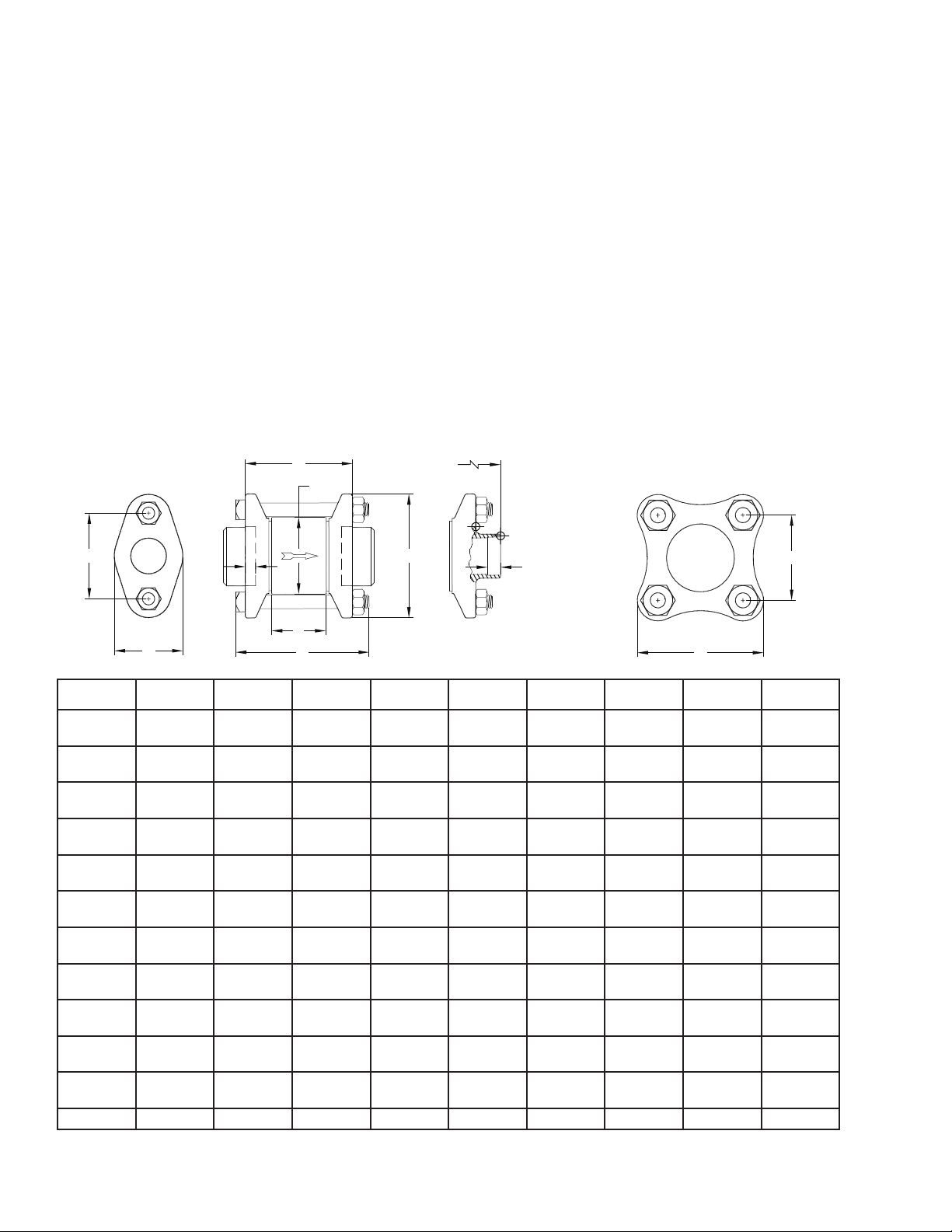
INSTALLATION DIMENSIONS
Body:
5/8” thr u 1¼”: S tee l, ASTM A108, zinc chromate
plated
1½” thru 4”: Ductile iron, ASTM A536, zinc chromate
plated
Seat Disc: St ainless steel
Seat Cartridge:
5/8” t hru 1¼”: Sta inless s teel, ASTM A582
1½” thru 4”: Steel, ASTM A108, zinc chromate
plated
Spring: Stainl ess s tee l
Safe Worki ng Pressure: 400 psig (27 bar), 6 00 psig
(40 bar) for CO2
Op eratin g Tempera tur e: -60 º F to 24 0ºF (- 50ºC to
115°C)
INSTALLATION DIMENSIONS
INSTALLATION
Val ve may be loc ated in any position. Arrow on valve
body should match direction of flow. Se cur e valve
with gaskets between flanges and tighten bolts evenly.
Do not use this valve or any component to alig n pipes
or tighten gap b etween f lan ges .
Do not install on inlet side of solenoid valves or control
valves with electric shut-off or shut-of f valves unless
a relief valve is used from therein between piping. Do
not insta ll on inl et side of outlet pressure regulators
where l iquid may become tra ppe d. In stead, c hec k
valves should be located on outlet side of these valves.
Check valves can be close- coupled to other matching
solenoi d va lves, p res sur e reg ulato rs, o r str ainers by
using a Male Adapter Ring a nd longer bolts supplied
when so specified on orde r. For pr oper flange gasket
sealing, care must be taken when threading or welding
to assure fl ang es are p arallel to each ot her and
perpendicular to pipe. Also, gaskets should be lightly
oile d and all bolts m ust be tig htened evenl y.
A
J
F
H
D
B
K
H
E
G
DI MEN S IO N
LE TT E R
A
B
C
D
E
=
F
G
H
J
K
Valve C v
(Kv)
Pipe S iz e 1/2”, 3/4 ” 3/4” 1” 1-1/4” 1-1/2 ” 2” 2-1/2 ” 3” 4”
HC K4 -2
5/ 8” PO R T
2. 50”
(6 4m m)
3.19 ”
(81mm)
3. 50”
(8 9mm)
0.38”
(10mm)
1.03”
(26m m)
1.5 0”
(3 8mm)
1.5 6”
(20m m)
2.19 ”
(56m m)
3. 26”
(8 3mm)
0.33 ”
(8 mm)
5. 8 (5 ) 8. 2 (7) 11.7 ( 10) 14.0 ( 12) 39 (33 ) 50 (4 3) 74 (63 ) 9 3 (8 0) 210 (180)
HC K4 - 3
3/4 ” PO RT
3. 25”
(8 3mm)
4.50 ”
(114mm)
4.50 ”
(114mm)
0.50 ”
(13mm)
1.2 2”
(31mm)
2. 37 ”
(6 0mm)
2. 50”
(6 4m m)
3.12”
(7 9mm)
4.00 ”
(102m m)
0.49 ”
(12mm)
C
HC K4 - 4
1” PO RT
3. 25”
(8 3mm)
4.50 ”
(114mm)
4.50 ”
(114mm)
0.50 ”
(13mm)
1.2 2”
(31mm)
2. 37 ”
(6 0mm)
2. 50”
(6 4m m)
3.12”
(7 9mm)
4.00 ”
(102m m)
0.59 ”
(15mm)
HC K4 - 5
1-1/4 ” PO RT
3. 25”
(8 3mm)
4.50 ”
(114mm)
4.50 ”
(114mm)
0.50 ”
(13mm)
1.2 2”
(31mm)
2. 37 ”
(6 0mm)
2. 50”
(6 4m m)
3.12”
(7 9mm)
4.00 ”
(102m m)
0.62 ”
(16mm)
HC K4 -7
1-1/ 2” P OR T
5.06”
(129m m)
4.56 ”
(116m m)
6. 38”
(162m m)
0.75”
(19mm)
2. 56”
(6 5mm)
3. 62 ”
(92m m)
4.56 ”
(116m m)
3.06”
(78mm)
6.06”
(154m m)
0.7 1”
(18mm)
HC K4 - 8
2” P OR T
6.06”
(154m m)
4.56 ”
(116m m)
6. 38”
(162m m)
0.75”
(19mm)
2. 56”
(6 5mm)
3. 62 ”
(92m m)
4.56 ”
(116m m)
3.06”
(78mm)
6.06”
(154m m)
0.87 ”
(22m m)
HC K4 - 9
2-1/ 2” P OR T
6.06”
(154m m)
6.00”
(152 mm)
7.50 ”
(191mm)
1.0 0”
(25m m)
2. 92”
(74mm)
4. 84”
(123m m)
6.00”
(152 mm)
4.00 ”
(102m m)
7.06 ”
(179 mm)
0.96”
(24mm)
G
HC K4 - 0
3” P OR T
6.06”
(154m m)
6.00”
(152 mm)
7.50 ”
(191mm)
1.0 0”
(25m m)
2. 92”
(74mm)
4. 84”
(123m m)
6.00”
(152 mm)
4.12”
(105m m)
7.06 ”
(179 mm)
1.08”
(27mm)
HC K4 -1
4” PO R T
6. 39”
(162m m)
7.13”
(181m m)
8.00”
(203 mm)
1.0 0”
(25m m)
3. 50”
(8 9mm)
6.06”
(154m m)
7.13”
(181m m)
5.00”
(127mm)
9.89 ”
(251mm)
1.40”
(3 6mm)
= “E” dime nsi on i s che ck v alve b ody o utsid e edge to out sid e ed ge. Flan ge gr oove d epth: nomi nal 0.12” eac h of t wo;
ga sket thic kne ss: n omina l 0.0 6” e ach of tw o.
C401 e
JUL 2006
2
 Loading...