

Hansen HA4A, HA4AS, HA4AO, HA4AB, HA4AP Specifications, Applications, Service Instructions & Parts
...
Contents
Page
Regulator Variations
3
Capacities
4–5
Control Modules (Pilots)
6
Main Regulators Only (AR1, AR3)
7
Operation and Adjustment
8–11
Installation Dimensions
12–13
Parts List
14–18
Service and Maintenance, Abbreviations
19
Ordering Information, Conversions
20
Regulator With Electric Wide Opening
HA4AB
INTRODUCTION
These advanced-design, strong-bodied, precisionmanufactured MODULAR regulators are superior in
their ability to overcome dirt and sticky oil during
opening and tight closing. Models are available for
nearly every control function requirement of industrial
ammonia and commercial halocarbon refrigeration.
These regulators are ideal for cold storage plants,
poultry plants, meat packing, fish processing, freezers,
ice plants, breweries, bottling plants, heat recovery
units, petrochemical plants, pharmaceutical plants,
supermarkets, and many others.
APPLICATIONS
Evaporator Pressure Control
Defrost Pressure Control
Condensing Pressure Regulation
Receiver Pressure Control
Hot Gas Bypass Capacity Regulation
Suction Pressure Control
Air or Liquid Temperature Regulation
Internal System Pressure Relief
Bulletin R429d
MAR 2002
Specifications, Applications,
Service Instructions & Parts
HA4A MODULAR
PRESSURE REGULATORS ¾"
THROUGH 6" PORT (20 MM
THROUGH 150 MM)
Various Connection
Styles and Sizes
for Refrigerants
KEY FEATURES
ADDITIONAL FEATURES
Tolerant of Dry Systems
For Ammonia, R22, R134a and other Hansen-
Approved Refrigerants
Wide Range of Options
Inlet, Outlet, or Differential Pressure
Wide Pressure Ranges
Electric Shut- Off, Dual, or Wide-Opening Available
Safe Working Pressure: 400 psig (27 bar)
CSA Certified, CRN for Canada

MATERIAL SPECIFICATIONS
R429d
2
MAR 2002
Body:
¾" through 4": Ductile iron, ASTM A536
5" & 6": Cast steel, ASTM A352 LCB
Adapter: Ductile iron, ASTM A536
Piston: Steel, disc type, Teflon piston seal
V-Port/Seat: ductile iron, with Teflon seat
Main Seat: ¾" through 1¼": integral ductile iron
1½" through 6": stainless steel, removable
Gaskets: Nonasbestos, graphite composite
Manual Opening Stem: Steel, plated Pilots:
Stainless steel trim
Pilot Orifice: Stainless steel Flanges:
Forged steel, ASTM A105
Safe Working Pressure: 400 psig (27 bar) Operating
Temperature: –60F to +240F (–50°C to
+115°C), lower temperatures possible at
pressure downratings
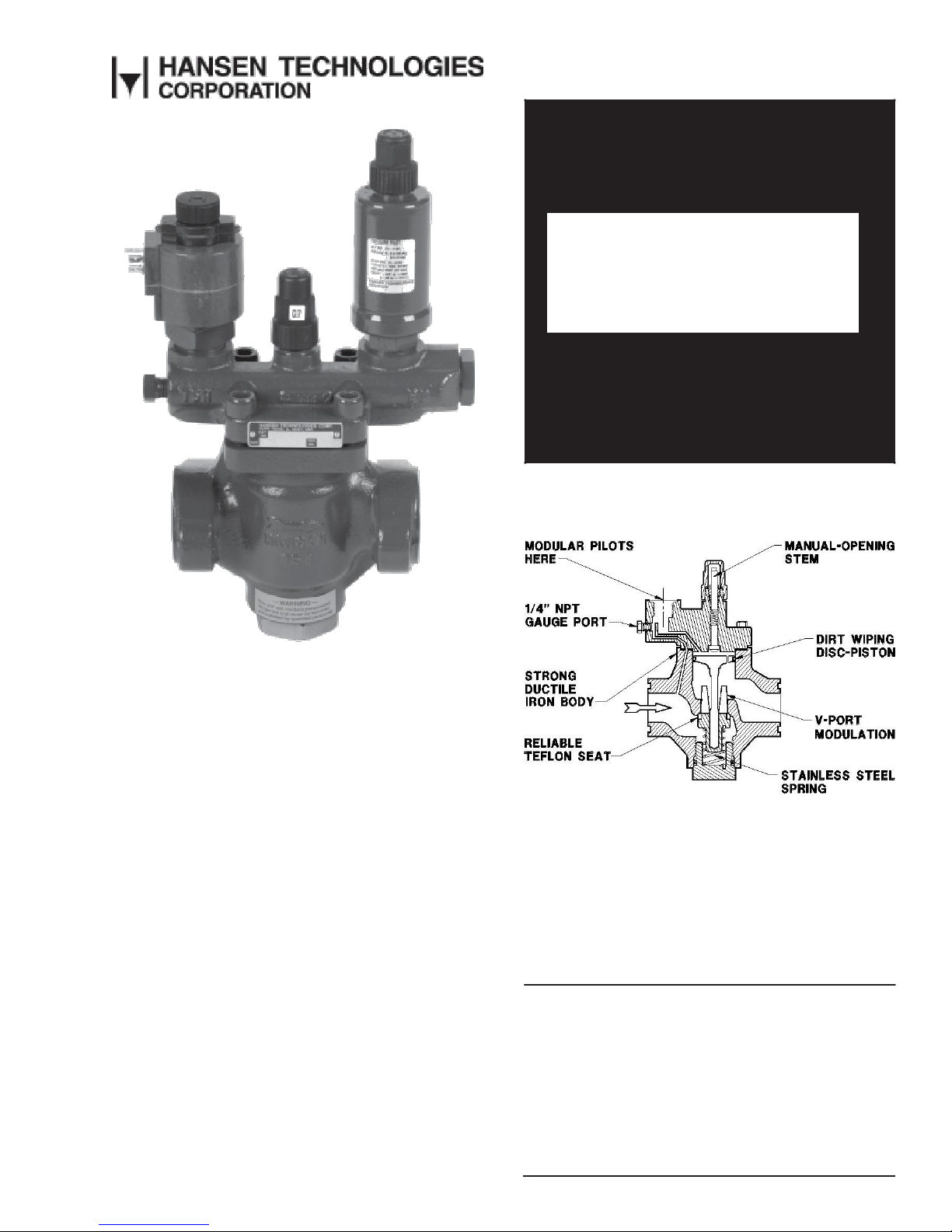
ADVANTAGES
These valves combine modern design and new age
materials with advanced manufacturing techniques and
intense quality control to offer a significantly superior
and reliable product. Their ductile iron bodies are
stronger and more rugged than common cast iron, or
so called semi-steel (class B iron), valves. They are
more dirt resistant than full skirted- piston-design
valves. All regulators use energized Teflon dirt-wiping
piston seals which operate reliably, even under dry, oilfree conditions. The screw-on control modules (pilots)
are easy to change and can be used on all valve sizes.
All valves incorporate Teflon seating and stainless
steel spring closing. Manual-opening stems are located
on top of valves, up and away from dirt and rust
particles to avoid thread jamming. Nonasbestos
gaskets are standard. These standard regulator valves
use the same flanges and spacing as R/S model A4A,
except 1¼" (32 mm). Special Hansen 1¼" 4-bolt
regulators are available from stock to exactly replace
R/S 1¼" A4A only.
SIZING
Proper regulator valve sizing is important for smooth
operation and long, trouble-free life of the valve.
Therefore, capacity of the regulator at both the
maximum and minimum flow and pressure drop should
be analyzed. Pressure regulators will operate
satisfactorily to approximately 15% of the maximum
capacity of valve based on the corresponding pressure
drop. In extreme cases, downsizing or two smaller
regulators in parallel are necessary. For pressure drops
exceeding 45 psi (3.1 bar), special construction may be
required. Contact the factory.
INSTALLATION
Regulators should be protected from dirt and moisture
during storage. The arrow on the body should be in the
normal direction of refrigerant flow. These valves will
not prevent reverse flow; use check valves where
necessary. Regulators are normally in horizontal pipe
lines with pilots and manual -opening stems on top. Do
not rotate the position of the valve adapter or the valve
will not operate.
The system should be free of dirt, weld slag, and rust
particles. Regulators can be equipped with separate,
close-coupled inlet strainers. No small, hidden, internal
screens are used. Gauges and gauge valves should be
installed on the inlet and outlet to help in system
diagnosis. Because of the many regulator pilot
combinations, during installation of a large job, the
regulator nameplates should be checked against piping
drawings to guarantee proper function for each
location. Where pilot solenoid control modules are
used, the nameplate coil voltage should be checked
before wiring. Pipe sizing, anchoring, valve rating,
system design, and other precautionary factors should
be taken into consideration to ensure “liquid hammer”
will not occur when the valve opens or closes.
The 5" and 6" valves are type HA4W with integral butt
weld end only. These steel-bodied regulators are
directly welded into the pipe line. During welding, the
manual-opening stem should be opened downward
several turns to protect the Teflon seat from weld heat.
Welds should be annealed as necessary in accordance
with good practice. Painting of valves and welds is
recommended for corrosion protection. Pipe covering,
where applied, should have proper moisture barrier.
Before putting valves into service, all pipe connections,
valve seats, cover seals, and stem seals should be
tested for leaks at pressure levels called for in
appropriate codes.
ELECTRICAL
When the electric shut-off, wide-opening, or dual
feature is supplied, a Hansen low-wattage, molded
electrical coil is included. Standard coil voltages are
115V, 208/230V, or 24V at 50/60Hz. Other voltages
available. The coil properly operates between 85% and
110% of the rated voltage. Coils should only be
energized while on the pilot solenoid tube. Unless
otherwise specified, the standard coil with a ½" fitting
for conduit is supplied with valves.
A watertight solenoid coil with 18" (450 mm) long wire
pigtail leads and a steel frame housing with a ½"
conduit fitting is standard.
Optional DIN Plug Coils are for grounded cord
connections and include the necessary DIN plug socket
with gasket.
Coils with Junction Boxes are optional. Integral, steel
junction box for connection of the 18" (450 mm) long
wire pigtail leads.
Vibration-resistant, bright, long-life, neon pilot lights
are available. These pilot lights operate on primary
voltage; a special coil with secondary winding is not
necessary. Optional watertight pilot light assembly is
also available; see page 20.
HA4AO OUTLET
PRESSURE REGULATOR
Controls outlet pressure by opening
as downstream pressure falls below
the set point. Used for hot gas to
provide artificial refrigeration loading,
for condenser and receiver pressure
control by means of gas bypass,
limiting hot gas pressure supply in
defrosting evaporator in conjunction
with liquid drain traps, or
for HA4AO
compressor suction pressure limitation.
Can be combined with electric shut-off,
temperature-operated, dual, or wide-
opening features. See page 11.
HA4AP PNEUMATICALLY
COMPENSATED REGULATOR
Commonly used for precise air or liquid
temperature
control
via pneumatic
controller. An air, vapor, or liquid
pressure signal to the control module
bonnet increases inlet pressure from
HA4AP
the set-for pressure value at a 1:1 ratio.
See page 12.
HA4AT TEMPERATURE
OPERATED REGULATOR
The vapor pressure capillary tubing
and bulb system modulates the
regulator open
as
temperature
increases to control air or liquid
temperature. See page 12.
HA4AT
HA4AJ ELECTRONICALLY
CONTROLLED REGULATOR
Electronic pilot and controller provides
very precise temperature control of
various cooled media under fluctuating
load conditions. See page 12.
HA4AJ
HA4AM ELECTRIC MOTOR
COMPENSATED REGULATOR
Commonly used for precise room
temperature control or liquid chiller
control. The controlling motor changes
regulator
pressure
setting
in
accordance
with a temperature
controller. See page 13.
3
R429d
MAR 2002
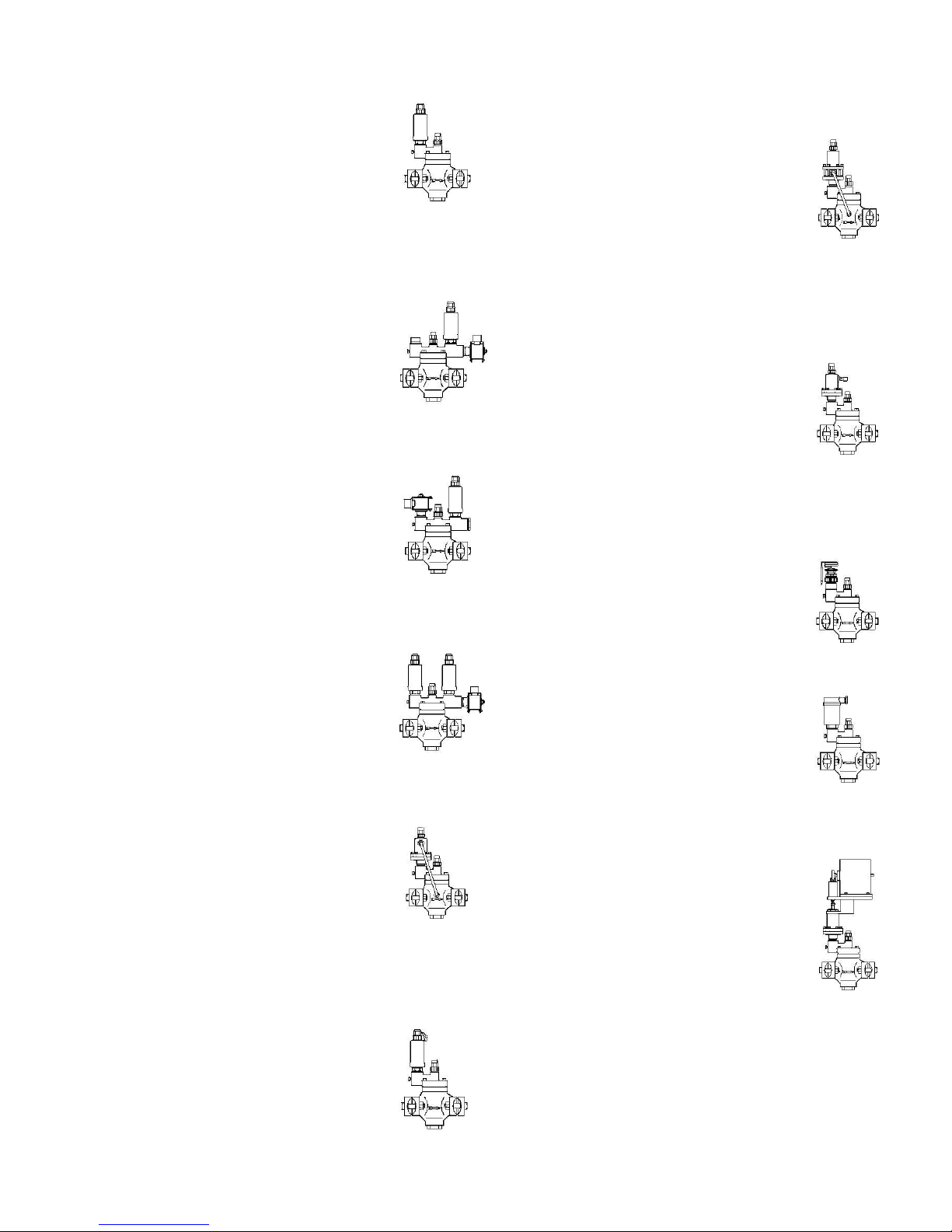
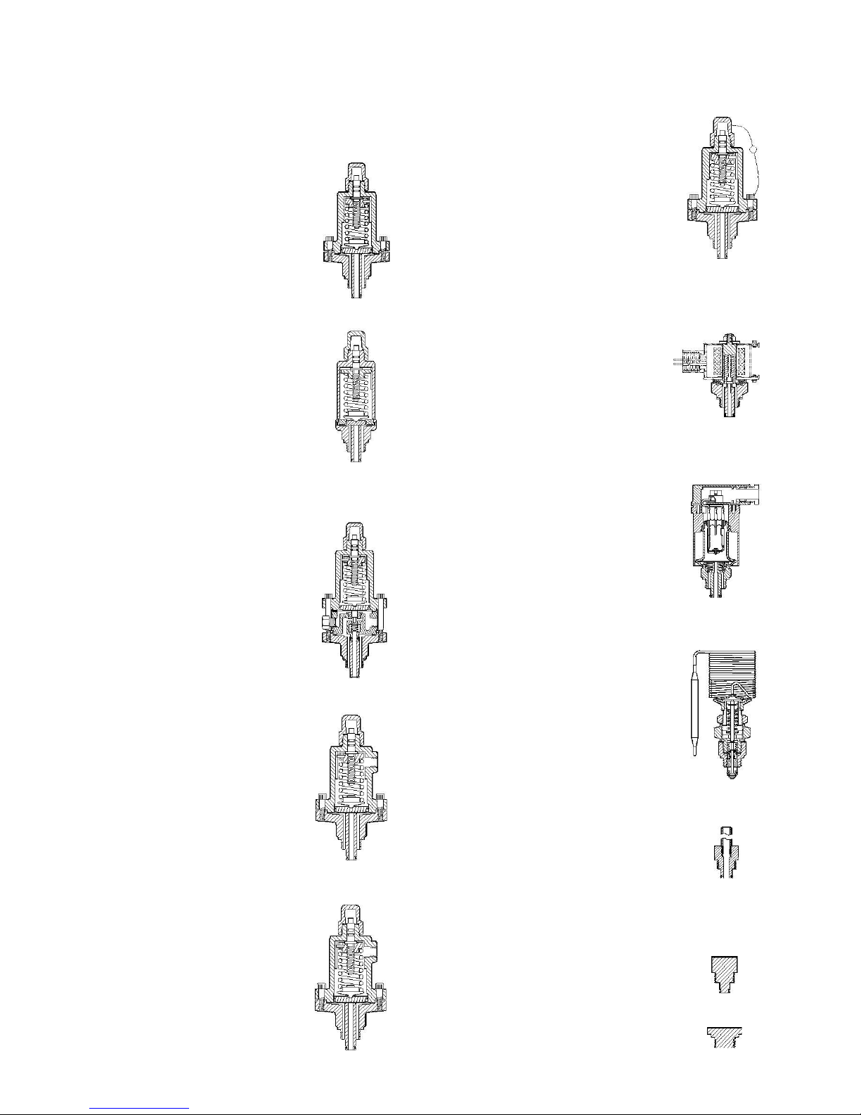
HA4A STANDARD REGULATOR
REGULATOR VARIATIONS
This most common pressure regulator
modulates to control evaporator
pressure, condensing pressure,
pressure in a vessel, or pressure in a
portion of a system. It is frequently
called an evaporator pressure regulator
(EPR) or back pressure regulator. Opens
on rising inlet pressure. See page 10.
Shown with M3W pilot.
HA4AS REGULATOR WITH
ELECTRIC SHUT-OFF
This control is commonly used for
temperature control or defrost.
Regulates at the set-for pressure when
energized. When de-energized, the valve
closes tight regardless of the pressure
setting. See page 11.
HA4AB REGULATOR WITH
ELECTRIC WIDE OPENING
Commonly regulates for defrost or
temperature, but opens wide for
maximum cooling. Regulating at the setfor pressure when de-energized;
regulator opens when energized. See
page 11.
HA4AD DUAL PRESSURE
REGULATOR
Regulates (evaporator) pressure at a
setting when energized, and at a higher
setting for defrost, temperature control,
or pressure relief when de-energized.
See page 11.
HA4AL DIFFERENTIAL
PRESSURE REGULATOR
Commonly used as liquid pump relief,
condenser-receiver pressure difference
control, discharge pressure boosting for
defrosting or heat recovery, and other
similar applications. This control
modulates to maintain the set-for
difference between inlet and outlet
pressure. See page 10.
HA4AK RESEATING
RELIEF REGULATOR
Used for defrost, high-to- low side relief,
or nonatmosphere relief to other parts of
the system. This control opens when
system upstream pressure is above the
tagged and sealed set point pressure,
and repeatedly reseats after operation.
See page 10.
HA4A
HA4AS
HA4AB
HA4AD
HA4AL
HA4AK
HA4AM
NOTE: Many other control functions can be achieved
by combining the control modules in different
arrangements. For example: a dual regulator with
electronic pilot and secondary relief pilot; i.e. HA4ADJ.
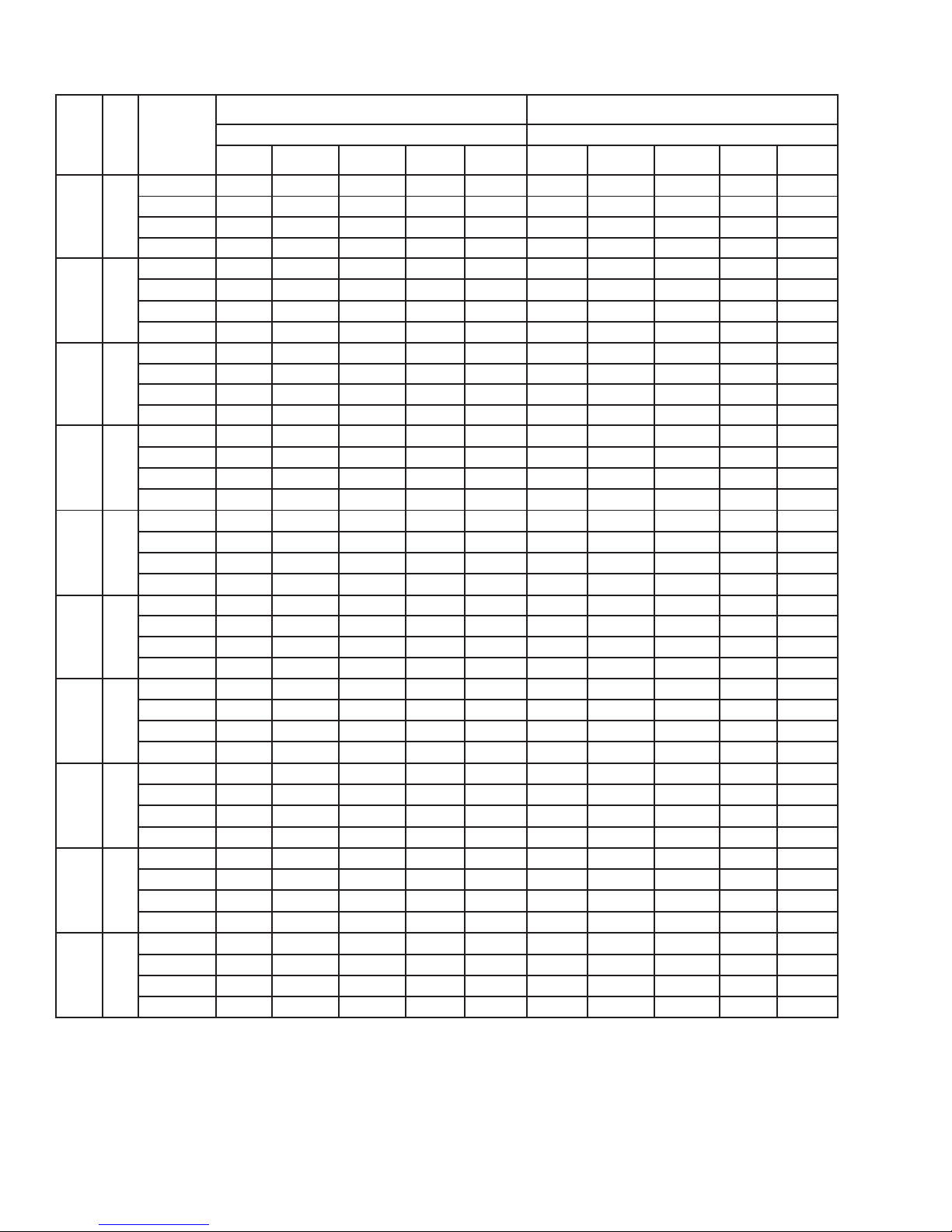
PRESSURE
R 717
R22
PORT
Cv
DROP
EVAPORATING TEMPERATURE
EVAPORATING TEMPERATURE
SIZE
(Kv)
ACROSS
(mm)
–40F†
–20F†
0F
+20F
+40F
–40F†
–20F† 0F
+20F
+40F
VALVE‡
(–40°C)
(–28.9°C)
(–17.8°C)
(–6.7°C)
(+4.4°C)
(–40°C)
(–28.9°C)
(–17.8°C)
(–6.7°C)
(+4.4°C)
2 psi
4.7 6.4 7.4 9.5
12 2.1
2.8
2.8 3.6
4.4
3
/4"*
6.4 5 psi
6.7 9.7 8.7
15
19 3.2
4.3
4.4 5.5
6.9
(20)
(5.5)
10 psi
a
13
15
20
26
a
5.8
6.0 7.7
9.6
20 psi
a
a
19
27
35
a a
7.8
10 13
2 psi
8.5
12
13
17
22 3.9
5.2
5.2 6.5
8.0
1"
11.7 5 psi
12
18
16
27
34 5.8
7.9
8.0
10 13
(25)
(10)
10 psi
a
23
28
37
47
a
11
11
14 18
20 psi
a
a
36
49
64
a a
14
19 24
2 psi
12
16
19
24 31
5.4
7.2
7.2
9.1
11.3
11/4"
16.4 5 psi
17
25
22
38
48 8.1
11
11
14 18
(32)
(14)
10 psi
a
32
39
52
66
a
15 15
20 25
20 psi
a
a
50
69
90
a a
20
26 34
2 psi
25
35
40
52
65 12
15 15
19 24
11/2"
35
5 psi
37
53
48
81
102 17
24
24
30 38
(40)
(30)
10 psi
a
69
84
111
141
a
31
33
42 53
20 psi
a
a
106 147
193
a a
43
56 72
2 psi
34
47
54
70
87 16
21 21
26 32
2"
47
5 psi
49 71
64
108
137 23
32
32
41
51
(50)
(40)
10 psi
a
92
113 149
190
a
42
44
56
71
20 psi
a
a
143 198
259
a a
57
76 96
2 psi
56
77
89
114
143 25
34
34
43 53
21/2"
77
5 psi
81
116 105 177
224 38
52
53
67 83
(65)
(66)
10 psi
a
151 185 243
311
a
69
72
92
116
20 psi
a
a
234 324
424
a a
94 124
158
2 psi
76
104 120 154
193 34
46
46
58
71
3"
104 5 psi
109 157 141 239
303
51
70
71
90
112
(80)
(89)
10 psi
a
204 250 329
420
a
93
97 125
156
20 psi
a
a
316 438
572
a a
127 167
213
2 psi
121
166 191 246
309 55
73
73
92
114
4"
166 5 psi
174
251
226 382
483 82
112
114 144
179
(100)
(142)
10 psi
a
325 398 525
671
a
149
155 199
249
20 psi
a
a
505 699
913
a a
203 267
340
2 psi
176 242 278 358
450 80
107
107 135
166
5"
242 5 psi
254 365 329 557
704 120
163
166 210
261
(125)
(207)
10 psi
a
474 581 765
978
a
218
226 290
363
20 psi
a
a
736 1019
1331
a a
295 390
496
2 psi
300 412 475 611
768 136
182
183 230
283
6"
413 5 psi
434 624 562 950
1202
204
278
282 358
446
(150)
(354)
10 psi
a
809 991 1305
1669
a
371
386 496
620
20 psi
a
a
1256
1739
2272
a a
504 665
847
‡ 2 psi= 0.14 bar
5 psi= 0.35 bar
10 psi= 0.69 bar
20 psi= 1.38 bar
R429d
4
MAR 2002
SUCTION VAPOR CAPACITIES (TONS)
(1 Ton= 12,000 Btu/hr= 3.517 kW= 3042 kcal/hr)
*Optional 25% or 50% reduced capacity ¾" (20 mm) plugs are available for unusually low loads if requested.
† –40F (–40°C) and –20F (–28.9°C) capacities are based on a two stage system.
For liquid overfeed evaporator suction between normal 2:1 to 5:1 rate, add 20% to the evaporator load or use the next larger port
size to accommodate liquid volume accompanying the suction gas and to reduce impact velocity.
Conditions: Capacities are based on the evaporator temperatures shown and +86F (+30°C) liquid. R717: For each 10F (5.6°C) lower
liquid temperature, increase the above table capacity by 3%. R22: For each 10F (5.6°C) lower liquid temperature, increase the above
table capacity by 5%. To convert for R134a, multiply the R22 table values by 0.73 (accuracy within 8%). For other refrigerant
capacities and suitability, contact the factory.
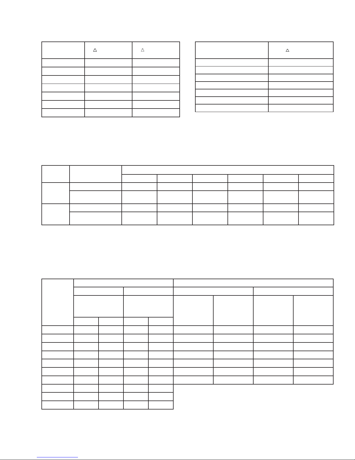
LIQUID CAPACITIES (U.S. GPM)
PORT SIZE
R717
R22
P= 30 psi
P= 30 psi
(mm)
(2 bar)
(2 bar)
3
/4"
(20)
45
30
1"
(25)
82
56
11/4"
(32)
114
78
11/2"
(40)
256 168
2"
(50)
324 230
21/2"
(65)
553 377
3"
(80)
733 505
PORT SIZE
OIL
P= 30 psi
(mm)
(2 bar)
3
/4"
(20)
48
1"
(25)
87
11/4"
(32)
122
11/2"
(40)
260
2"
(50)
350
21/2"
(65)
574
3"
(80)
775
R EFRIG.
APPLICATION
PORT SIZE (mm)
3
/4" (20)
1 " (25)
1
1
/4" (32)
1
1
/2" (40)
2 " (50)
2
1
/2" (65)
Hot Gas Solenoid *
9 to 15
15 to 28
28 to 39
39 to 73
73 to 106
106 to 165
R717
Defrost Relief
17 to 24
24 to 45
45 to 60
60 to 96
96 to 140
140 to 225
Regulator
Hot Gas Solenoid *
6 to 8
8 to 15
15 to 20
20 to 32
32 to 47
47 to 75
R22
Defrost Relief
6 to 8
8 to 15
15 to 20
20 to 32
32 to 47
47 to 75
Regulator
DISCHARGE GAS REGULATOR
HOT GAS BY-PASS TO SUCTION
R 717
R 22
R 717
R22
SIZE
+86F (+30°C)
+86F (+30°C)
+86F (+30°C)
+15F (–9.4°C)
+86F (+30°C)
+15F (–9.4°C)
Condensing
Condensing
(mm)
+140F (+60°C)
+140F (+60°C)
Condensing
Condensing
Condensing
Condensing
Discharge
Discharge
+140F (+60°C)
+15F (–9.4°C)
+140F (+60°C)
+15F (–9.4°C)
2 psid
5 psid
2 psid
5 psid
Discharge
Discharge †
Discharge
Discharge †
3
/4"**
(20)
17
27
6.1
9.5
88
27
32
12
1" (25)
31
49
11
17 160
49
58
22
1
1
/4" (32)
44
69
16 24
224
68
81
31
11/2"
(40)
94
147
33 52
479 146 173
66
2" (50) 126 197
45 70
643 196 232
89
21/2"
(65) 206 323
73
115
1054
321 380 146
3" (80) 279 437
99
155
1424
434 513 197
4" (100) 445 698 158
241
Hot gas bypass capacities are based on above given temperatures.
Liquid temperature is the same as condensing temperature.
5" (125) 649 1017 230
361
Evaporator temperature +40F (+4.4°C) or less for +86F (+30°C)
6" (150) 1108 1735 393
616
condensing; –22F (–30°C) evaporator for +15F (–9.4°C) condensing.
5
R429d
MAR 2002
APPLICATION: REFRIGERANT PUMP RELIEF
REGULATOR (HA4AL)
OIL CAPACITIES (U.S. GPM)
APPLICATION: SCREW COMPRESSOR OIL
PUMP RELIEF REGULATOR (HA4AL)
Capacities assume no gas flashing. No capacity correction
Capacities based on oil with less than 300 SSU viscosity.
required for temperatures between –40F (–40°C) and +40F
(+4.4°C).
HOT GAS DEFROST NOMINAL VALVE SIZING CAPACITIES
(DEFROSTING EVAPORATOR SIZE TONS)
*Or an outlet pressure regulator with electric shut-off (HA4AOS).
Evaporator tons at 10F (5.6°C) TD (temperature differential), valve capacities are conservative. These capacities can be modified up
or down depending on type of evaporator, temperature, mass, frost thickness, defrosting time, etc. Typical for –20F (–28.9°C)
evaporator.
GAS CAPACITIES (TONS)*
(1 Ton= 12,000 Btu/hr= 3.517 kW= 3042 kcal/hr)
= Bypass from intermediate pressure at saturation temperature to booster suction.
* These capacities are not for hot gas defrost relief. See the chart in the middle of this page.
** Optional 25% and 50% reduced capacity ¾" (20 mm) plugs are available.
Discharge gas capacities are based on +15F (+10°C) evaporator temperature.
M3W
OUTLET PRESSURE
Opens as outlet pressure drops. For hot
gas bypass to suction or for controlled
supply pressure of defrost hot gas. Also
used for compressor suction pressure
limiting (crankcase pressure regulator).
¼" NPT connections for outlet pressure
gauge and sensing line (tubing not
included). Range B, 30 to 300 psig (2 to
21 bar), Part 75-1101; or Range V, 20" to
130 psig (–0.67 to +9 bar), Part 75-1100.
M3O
Catalog M3O, specify range.
RESEATING RELIEF
Opens wide when pressure exceeds
pressure setting and repeatedly reseats
after operation. Defrost relief or high-
to-low system relief. Set and tagged. The
standard setting for ammonia defrost is
70 psig (4.8 bar). Range A, 0 to 150 psig
(0 to 10 bar), Part 75-1103; or Range B,
30 to 300 psig (+2 to 21 bar), Part Number
75-1104. Catalog M3K.
Compact welded pressure pilot. Range
A, 0 to 150 psig (0 to 10 bar), Part 75-1127.
M3K
Standard on valve sizes ¾" to 1¼".
Catalog M3KW.
SOLENOID
Normally closed. Opens wide when
energized. Requires coil. See page 2
for coil selection. Less coil: Part
70-1052, Catalog MS.
MS
ELECTRONICALLY
CONTROLLED
Mounted electronic actuator changes the
pressure set point in conjunction with a
controller and temperature sensor for
either air or liquid. Very precise. See page
12 for the control package which includes
the necessary controller and sensor.
Range: J1, 0 to 85 psig (0 to 6 bar), Part
27B1140; or J2, 25 to 115 psig (1.7 to 8 bar),
M3J
Part 27B1141. Catalog M3J.
TEMPERATURE OPERATED
Bulb opens the control module on
temperature rise to maintain a constant
temperature. Part 27B1110 with a range
of –40F to +30F (–40°C to 0°C) or Part
27B1111 with a range of +15F to +75F
(–10 to +25°C). Catalog M3T.
M3T
EXTERNAL CONNECTION
Enables a remote pressure source to be
introduced to the control via a pilot line
(replaces a pilot). ¼" NPT with separate
4" (100 mm) long weld nipple, Part
M3E25
35-1015, Catalog M3E25.
BLANKING PLUGS
To be used in a control module port when
the port is not utilized. Stopping plugs
have square head and are marked with
M3S
“0” (75-1063). Straight through flow plugs
have a hex head and are marked with
“1” (75-1064). Catalog M3S (stopping)
M3B
or M3B (straight through).
R429d
6
MAR 2002
CONTROL MODULES (PILOTS) FOR ANY REGULATOR
When installed, these control modules (pilots) enable
the main regulator to perform different control
functions (see page 3, Regulator Variations). Pilots are
normally factory installed, but can be retrofitted or
interchanged in the field. The nonrising stem can be
adjusted by using a ¼" wrench. Catalog
numbers are for the screw-on pilot module.
Interchangeable with Danfoss PM Series,
size permitting.
INLET PRESSURE
Opens as inlet pressure rises. Range: A, 0
to 150 psig (0 to 10 bar), Part 75-1097;
or B, 30 to 300 psig (2 to 21 bar), Part M3 75-1098.
Also, Range V, 20" to 130 psig
(–0.67 to +9 bar), Part 75-1099. Catalog M3.
Compact welded pressure pilot. Range A,
0 to 150 psig (0 to 10 bar), Part 75-1126.
Standard only on valve sizes ¾" to 1¼".
Catalog M3W.
DIFFERENTIAL PRESSURE
Maintains set- for differential between
inlet and outlet or other pressure source.
For pump relief or any differential control.
¼" NPT connection for pressure
sensing line (tubing not included). Range
A, 0 to 150 psi (0 to 10 bar) difference,
Part 75-1081, Catalog M3L.
PNEUMATICALLY
COMPENSATED
Air or other pressure in the bonnet raises
inlet pressure on a 1:1 ratio. ¼" NPT
connection. Range A, 0 to 150 psig (0
to 10 bar), Part 75-1081, Catalog M3P. M3P
M3L
 Loading...