

Hansen H5600A, H5600R, H5601, H5602, H5602R Specifications, Applications, Service Instructions & Parts
...
Pressure-Relief Valve
ONTAC
TPN-SNOITCENNOCDEDAERHT
BOTTOM INLET (DN) SIDE OUTLET (DN)
R0065H
1
/2T (15)PF"
3
/4T (20)PF"
A0065H
1065H
1
/2T (15)PF" PT (25)F"1
2065H
3
/4T (20)PF" PT (25)F"1R2065H
R2365H
3165H
T (25)PF1" 1
1
/4T (32)PF"
1
1
/2T (40)PF"
1
1
/4T (32)PF"
R3365H
4065H
R4365H
Bulletin K109i
AUG 2015
Specifications, Applications,
Service Instructions & Parts
REFRIGERANT
PRESSURE-RELIEF
VALVE
For Ammonia and
Halocarbon Gas Service
Safety Relief to Atmosphere
INTRODUCTION
Designed to provide emergency relief from excessive pressure
in refrigerant-containing vessels, they are built in strict
conformance with ASME Boiler and Pressure Vessel Code
requirements for safety relief devices. Each valve bears the
ASME code symbol of certification (UV ). Their capacities
are rated by the National Board of Boiler and Pressure Vessel
Inspectors. These tamper-resistant valves are accurately set
and sealed by qualified technicians at the factory.
APPLICATIONS
Hansen pressure-relief valves help meet the requirements
of ANSI/ASHRAE 15 Safety Standard for Refrigeration
Systems as well as other worldwide codes. This standard
requires pressure vessels of all refrigeration systems to
be protected by a pressure-relief device or other approved
means to safely relieve pressure in the event of fire or
other abnormal conditions. Once installed, a properly
selected Hansen pressure-relief valve is ready to vent to
atmosphere any temporary excessive overpressure inside
of a vessel. After discharge, these valves will attempt to
reseat to minimize loss of refrigerant. However, once any
relief valve has discharged, it must be replaced as soon
as possible because debris may have settled on the seat
during discharge.
Hansen pressure-relief valves should be connected to the
vapor space of refrigerant vessels, heat exchangers, oil
pots, oil stills, pilot receivers, and elsewhere as may be
required by various codes.
Where dual pressure-relief valves are required, Hansen
offers the three-way valves and other components necessary
for assembly; see page 4. Rupture disc assemblies are
required when using Hansen pressure-relief valves for
halocarbon applications because the high cost of such
refrigerants demands extreme tightness, see bulletin K209.
Also, see Bulletin K129 for information on the EZ-SRV Relief
Valves. These pressure-relief valves offer a cartridge style
design for ease of replacement without disturbing the piping.
EZ-SRV pressure-relief valves are available in pressure
ratings to 600 psi (matching the H5600 “R” series capacities
through 400 psi). Liquid relief valves are also available in
the EZ-SRV series. EZLQ relief valves are designed and
rated for liquid applications.
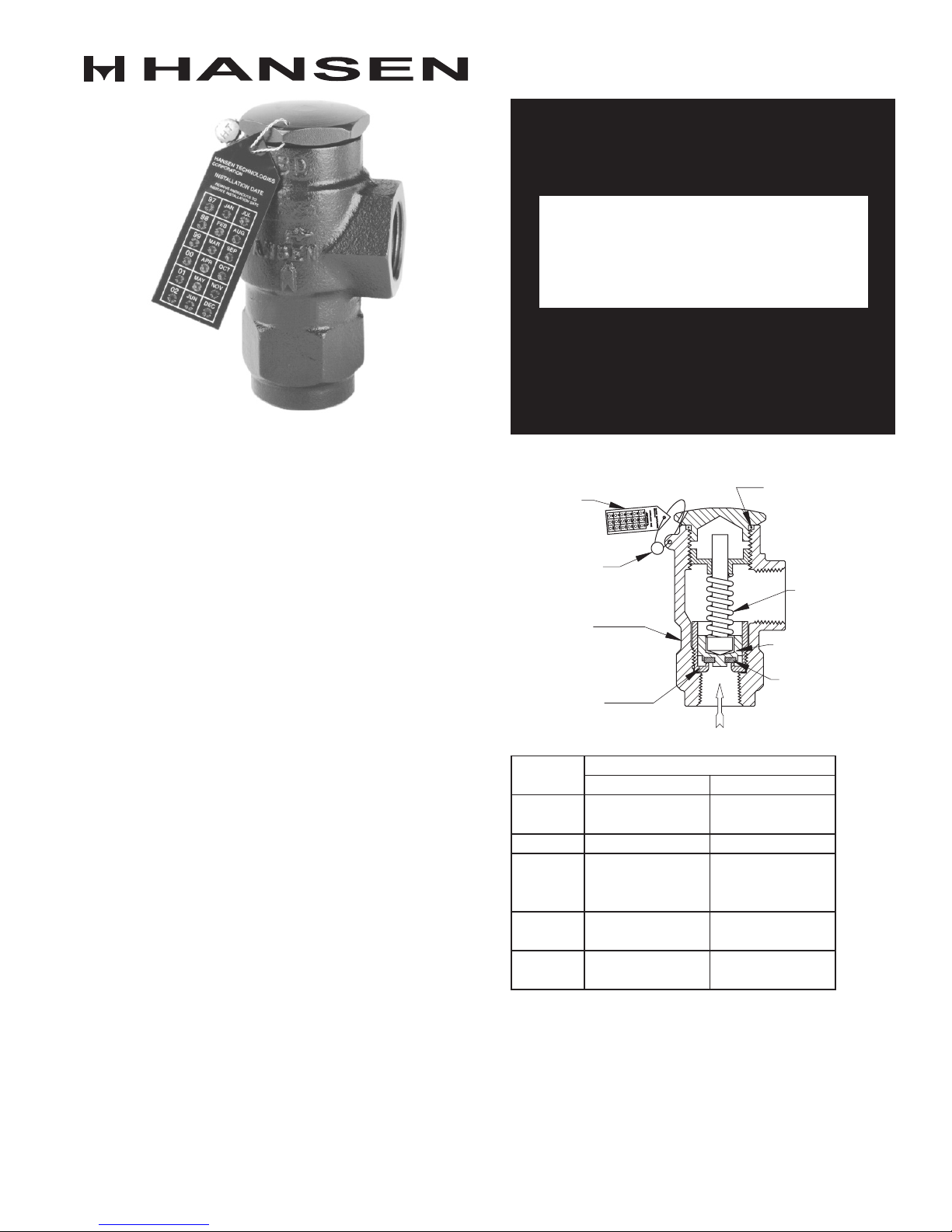
KEY FEATURES
INSTALLATION
DATE TAG
ACCURATELY
FACTORY SET
AND SEALED
DUCTILE IRON
BODY FOR ADDED
STRENGTH
STAINLESS STEEL
SEATINSERT
ORDERING INFORMATION
Specify catalog number, inlet/outlet connection size, and
pressure setting. For halocarbon applications, a rupture
disc assembly is required. See Rupture Disc Assembly
section of this bulletin. Standard pressure settings: 150*,
175, 200, 225, 250*, 275, 300*, 325, and 350 psig. (*Stock
pressure settings.) Custom pressure settings available;
may require extra delivery time. The H5600 “R” series
valves have reduced capacities, see page 2. CE marked
valves are available, add the letter “E” suffix to catalog
number (example: H5601/250E).
NEOPRENE O-RING
HELPS SEALVALVE
FROM MOISTURE
STAINLESS
STEEL SPRING
STAINLESS STEEL
PISTON
PREMIUM GRADE
VIRGIN TEFLON
SEATDISC
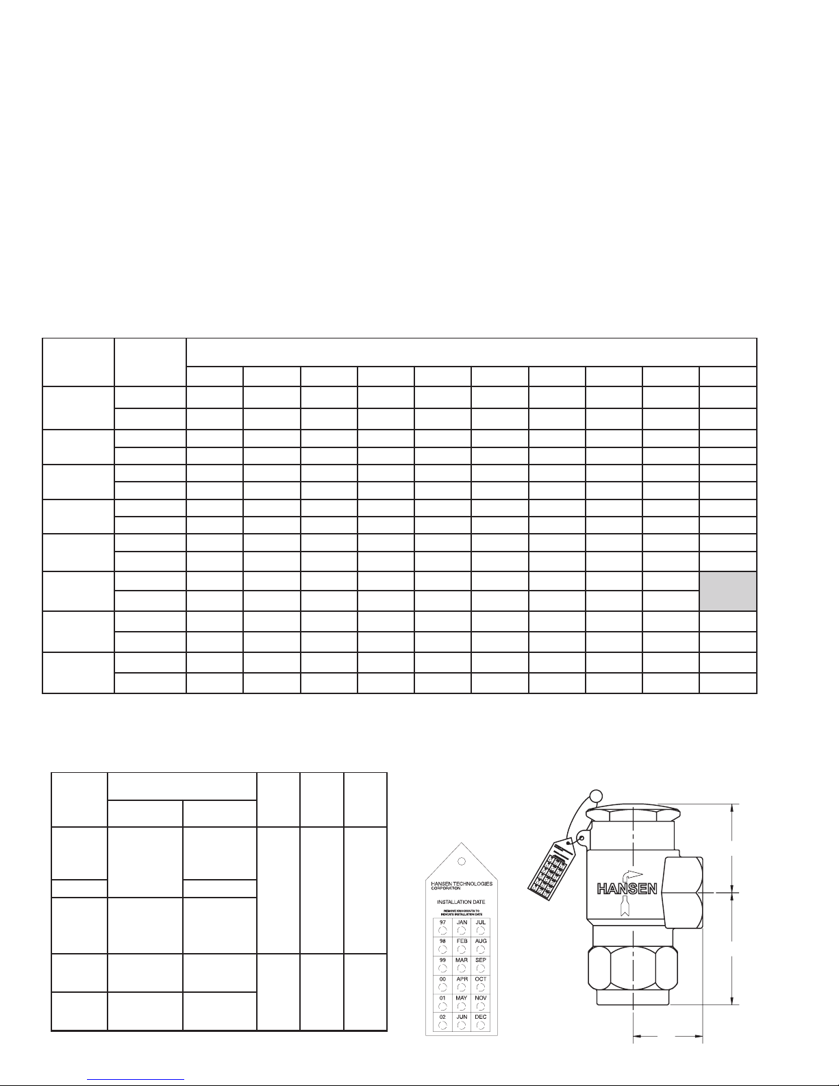
VALVE SIZING AND SELECTION
ONTAC
SNOITCENNOCDEDAERHT
TPN
A
(MM)B(MM)C(MM)
MOTTOB
T (DN)ELNI
EDIS
T (DN)ELTUO
A0065H
R0065H
1
/2T (15)PF"
3
/4T (20)PF"
2.13"
(54)
2.75"
(70)
1.63"
(41)
3.00"
(76)
4.13"
(105)
2.25"
(57)
1065H PT (25)F"1
2065H
R2065H
R2365H
3
/4T (20)PF" PT (25)F"1
1
3165H
R3365H
T (25)PF"1
1
/4T (32)PF"
1
1
/2T (40)PF"
4065H
R4365H
1
1
/4T (32)PF"
Step 1: Use the formula below, per ANSI/ASHRAE 15
Safety Standard for Refrigeration Systems to calculate the
minimum required discharge capacity in pounds of air per
minute. When selecting a dual pressure-relief valve system,
be aware that each individual valve must have sufficient
capacity to protect the vessel.
** This factor is not suitable when combustible materials
are within 20 feet (6.1 m) of the pressure vessel; refer to
relevant codes for corrected sizing method.
Example: To determine the minimum required capacity
of a relief valve for a vessel containing ammonia that
measures 16 feet in length and 6 feet in outside diameter,
the equation would be as follows: 0.5 x 6 x 16 = 48 lb/min.
Step 2: Determine the pressure setting needed. This
C=fDL
C = minimum required discharge capacity of
the relief device in pounds of air per minute.
f = factor for ammonia refrigerant is 0.5**,
factor for R-22 and R-134a refrigerants is 1.6**, for
other refrigerants see ANSI/ASHRAE 15 or contact
factory.
D = outside diameter of vessel in feet.
L = length of vessel in feet.
should be at or below the design pressure of the vessel.
The relief setting should also be at least 25% above the
maximum expected operating pressure to avoid “weeping”
of relief valves. The setting may be below (never above) the
design pressure of the vessel, but it is sometimes best to
match vessel design pressure and relief setting to minimize
the likelihood of a discharge.
Step 3: Refer to the Valve Capacity Ratings below and
select the valve with the required capacity (C) at the desired
pressure setting.
PRESSURE-RELIEF VALVE CAPACITY RATINGS (NATIONAL BOARD CERTIFIED)
ONTAC
R0065H
R2065H
R2365H
R3365H
R4365H
A0065H
1065H
2065H
3165H
4065H
RIA
YTICAPAC
nim/bl 5.01 2.21 8.31 4.51 0.71 6.81 2.02 8.12 5.32 7.62
mfcs 041 261 381 502 622 842 962 092 213 553
nim/bl 22 52 92 23 63 93 24 64 94 65
mfcs 292 733 283 724 274 715 165 606 156 147
nim/bl 82 33 73 14 64 05 45 95 36 27
mfcs 773 534 294 055 806 566 327 187 938 459
nim/bl 43 93 44 94 45 06 56 07 57 58
mfcs 944 815 685 556 427 397 168 039 999 6311
nim/bl 3.13 1.63 9.04 7.54 5.05 3
mfcs 714 084 445 806 276 637 997 368 729 5501
nim/bl 8.53 3.14 8.64 2.25 7.75 2.36 6.86 1.47 6.97
mfcs 674 945 226 596 867 148 319 689 9501
nim/bl 0.35 1.16 2.96 3.77 4.58 5.39 6.101 7.901 8.711 431
mfcs 407 218 029 8201 6311 3421 1531 9541 7651 2871
nim/bl 0.27 0.38 0.49 1.501 1.611 1.721 1.831 1.941 2.061 281
mfcs 859 4011 1521 7931 4451 1961 7381 4891 0312 3242
051 571 002 522 052 572 003 523 053 004
.55 1.06 9.46 7.96 3.97
)gisp(SGNITTESERUSSERPDRADNATS
Important Note: These are atmospheric relief valves. Settings equal pressure above atmosphere when outlet is connected via
proper piping to the atmosphere (outside). (scfm = Standard Cubic Feet per Minute)
INSTALLATION DIMENSIONS
K109i
AUG 2015
H5600 “R” Series capacity valves have green installation
date tags, while all others are blue.
A
B
C
2
 Loading...