

Hansen EZ-SRV, EZB-BT1, EZB-BT2, EZF-BT5, EZE-BT4 Specifications, Applications, Service Instructions & Parts
...
EZ-SRV™
Cartridge Pressure-Relief Valve with EZ-Fitting
Bulletin K129e
JAN 2014
Specifications, Applications,
Service Instructions & Parts
EZ-SRV™ CARTRIDGE
PRESSURE-RELIEF VALVES
For Ammonia and Halocarbon
Refrigeration Systems
INTRODUCTION
Hansen EZ-SRV™ cartridge pressure-relief valves protect
refrigeration pressure vessels and other refrigeration
system components from excessive pressure. If an
abnormally high pressure occurs, the cartridge pressurerelief valve will open to relieve the excess pressure,
preventing potential damage to equipment and injury
to personnel.
Hansen EZ-SRV™ relief valves are built in strict
conformance with both ASME Boiler and Pressure Vessel
Code requirements and ISO 4126 — Safety Devices for
Protection of Excessive Pressure. Each valve bears the
ASME code symbol of certification (UV). Valve capacities
are rated by the National Board of Boiler and Pressure
Vessel Inspectors (NB).
Refrigeration pressure-relief valves are recommended
for replacement at least every five years. However, if a
relief valve has discharged, it must be replaced as soon
as possible. Valve replacement with the Hansen EZ-SRV™
is fast and easy — saving significant time and expense
compared to traditional relief valves.
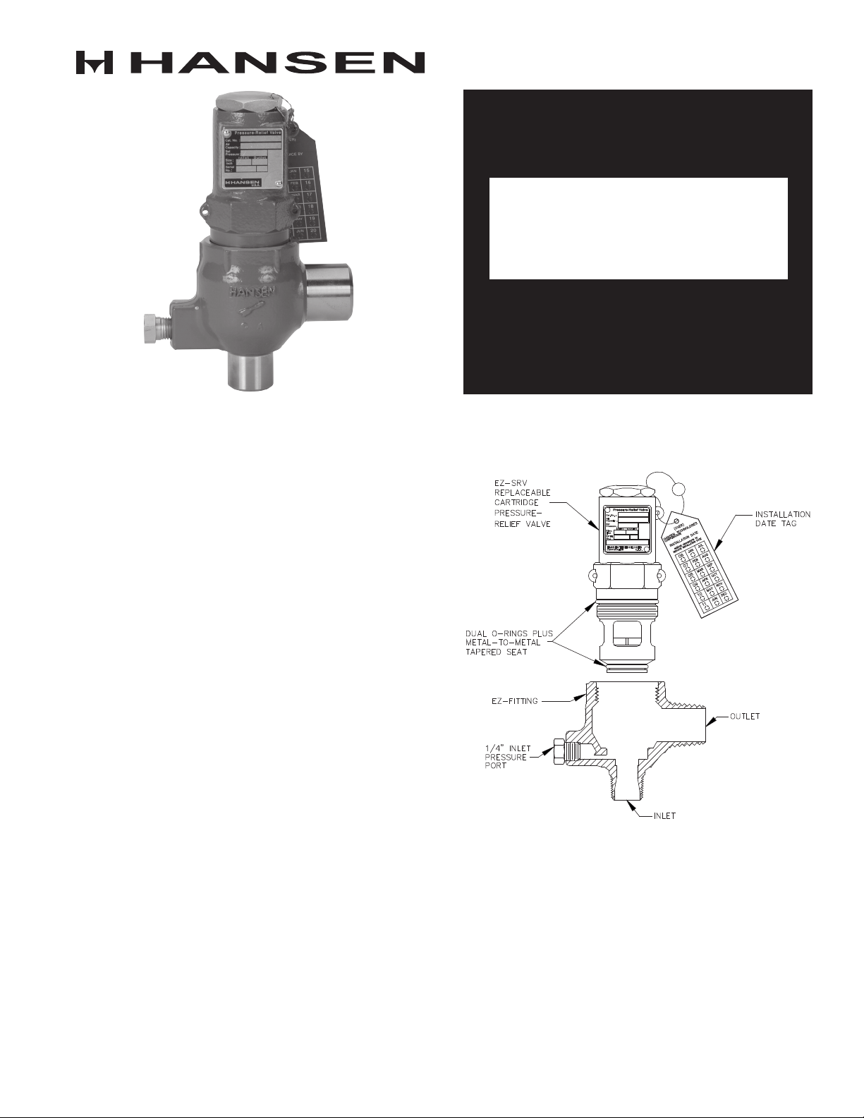
The cartridge valve can be replaced more safely than
previously available pressure-relief valves. The Hansen
EZ-Fitting has a ¼˝ NPT connection on the side of
the body. A ¼˝ gauge valve installed with a tell-tale
pressure gauge can indicate overpressure of a valve
and if pressure is present when servicing, the ¼˝ gauge
valve can also be used to safely bleed-off residual
pressure between the three-way manifold valve and
the EZ-SRV™ valve.
KEY FEATURES
Cat. No.
Air
Capacity
Set
Pressure
I n l e t
O u t l e t
Size
inch
Serial
No.
HANSEN TECHNOLOGIES
U.S.A.CORPORATION
ADDITIONAL FEATURES
Cartridge design allows quick and easy replacement.
Matched capacities to existing Hansen H5600
“R” series
Low blowdown (15% or less) for gas service
EZ-Fitting is a permanent fixture, available with
welded or threaded end connections
MPT inlet eliminates need for nipple
EZ-Adapter component available for retrofit of existing
Hansen relief valves
Liquid Rated Relief Valve (EZLQ) available
APPLICATIONS
Hansen EZ-SRV™ cartridge pressure-relief valves
typically are installed on pressure vessels to protect
from overpressure. Several design codes for refrigeration
systems require that pressure vessels have protection
from excessive pressure. For example, Hansen cartridge
pressure-relief valves comply with the requirements
of ANSI/ASHRAE Standard 15 Safety Standard for
Refrigeration Systems, and ANSI/IIAR 2 Equipment,
Design, and Installation of Closed-Circuit Ammonia
Mechanical Refrigerating Systems. Once installed,
a properly selected Hansen EZ-SRV™ cartridge
pressure-relief valve will vent to atmosphere excessive
overpressure. After discharge, these valves will quickly
reseat to minimize loss of refrigerant. After discharge,
relief valves must be replaced as soon as possible
because debris may have settled on the seat, allowing
the seat to leak out refrigerant. Hansen EZ-SRV™ valves
must be installed in the vapor space above the liquid
level of any vessel or component which contains liquid
and vapor. (Hansen offers the EZLQ, a liquid relief valve
for use with ASME rated pressure vessels and is rated
U.S. GPM.)
MATERIAL SPECIFICATIONS
EZ-Fitting Body: ASME SA105 steel
EZ-SRV™ Car tridge: ASME SA395, ductile iron
Internal Seating Components: stainless steel
Piston: stainless steel
Seat O-rings: neoprene
Spring: stainless steel
Maximum Temperature Rating: 240°F (115°C)
Safe Working Pressure: 600 psig (41 bar)
Setting Range:
Gas Service: 150 to 600 psig (10.4 to 41 bar)
Liquid Service: 50 to 100 psid (3.4 to 6.9 bar)
Reseat Pressure (blowdown):
Gas Service: within 15% below set point
Liquid Service: within 20% below set point
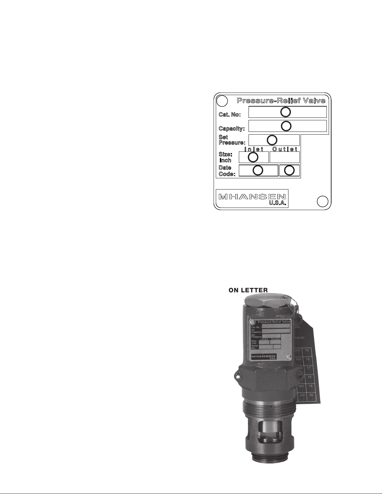
NAMEPLATE INFORMATION
The nameplate, located on the side of Hansen EZ-SRV™
cartridge pressure-relief valves, contains important
information about the valve pressure setting, capacity
and date of manufacture. The date code traces the
month and year the valve was built. Example: A valve
with Serial No. 06B 10, indicates that it was built in June
of 2010. See nameplate below for location of data and
photo of EZ-SRV replacement cartridge.
1
2
3
4
5
1. CATALOG NUMBER
2. AIR CAPACITY OR LIQUID FLOW RATE
ACCORDING TO THE SET PRESSURE
3. SET PRESSURE
4. INLET SIZE
5. MONTH AND DAY OF MANUFACTURE AND
VALVE NUMBER
6. YEAR OF MANUFACTURE AND CURRENT
REVISION LETTER
6
CODE AND STANDARD COMPLIANCE
ASME Boiler and Pressure Vessel Code, Section VIII,
Division 1
ANSI/ASHRAE Standard 15 Safety Standard for
Refrigeration Systems
ANSI/IIAR 2 Equipment, Design, and Installation of
Closed-Circuit Ammonia Mechanical Refrigerating
Systems
ISO 4126, Safety Devices for Protection of Excessive
Pressure
PED (Pressure Equipment Directive) Categor y IV
K129e
JAN 2014
EZ-SRV Replacement Cartridge
2
CAT NO
EZB
EZC
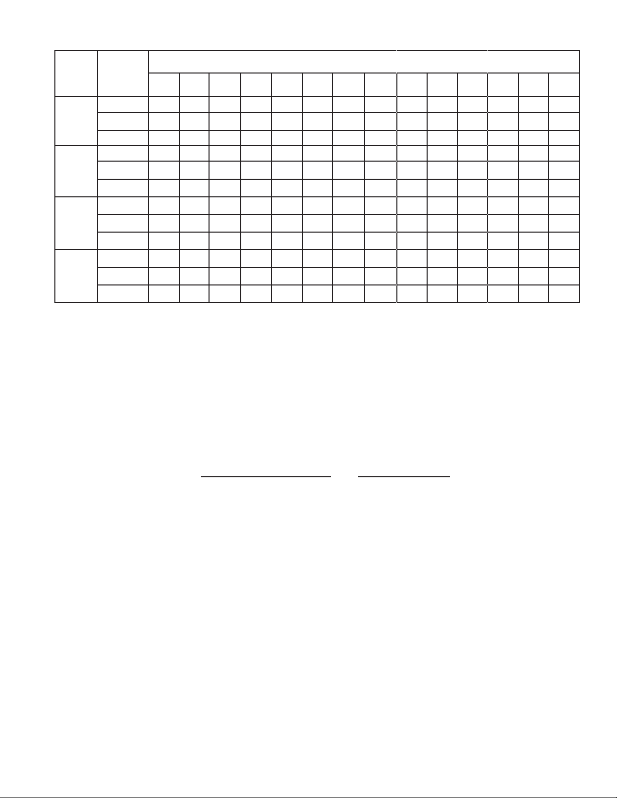
PRESSURE-RELIEF VALVE CAPACITY RATINGS
PRESSURE SETTING, PSIG
AIR
CAPACIT Y
lb/min 10.5 12. 2 13. 8 15.4 17.0 18.6 20.2 21.8 23.5 26.7 30 33 36 40
scfm 140 162 183 205 226 248 269 290 312 355 398 441 484 526
kg/hr 286 330 373 418 461 506 549 592 636 724 812 900 987 1075
lb/min 22 25 29 32 36 39 42 46 49 56 62 69 76 83
scfm 292 337 382 427 472 517 561 606 651 741 831 920 1010 1100
kg/hr 598 689 780 872 963 10 55 1146 123 8 132 9 1512 1695 1878 2061 2244
lb/min 28 33 37 41 46 50 54 59 63 72 – – – –
150
(10.3)
175
(12 .1)
200
(13. 8)
225
(15.5)
250
(17. 2 )
275
(19)
(BAR)
300
(20.7)
325
(22.4)
350
(24 .1 )
400
(27. 6 )
450
(31.0 )
500
(34.5)
550
(37. 9 )
600
(41. 4)
EZE
EZF
scfm 377 435 492 550 608 665 723 781 839 954 – – – –
kg/hr 770 888 1006 112 3 12 41 1359 147 7 15 95 1712 1948 – – – –
lb/min 34 39 44 49 54 60 65 70 75 85 – – – –
scfm 449 518 586 655 724 793 861 930 999 113 6 – – – –
kg/hr 916 10 56 119 6 1336 1477 16 17 1757 1897 2038 23 17 – – – –
SELECTION
Step 1: Use the formula below, per ANSI/ASHRAE Standard 15 Safety Standard for Refrigeration Systems, to calculate
the minimum required discharge capacity in pounds of air per minute (or kg/s). When selecting a dual pressure-relief
valve system, each individual valve must have sufficient capacity to protect the vessel.
C=fDL
C = minimum required discharge capacity of the relief device in pounds of air per minute (kg/s).
D = outside diameter of vessel in feet (m).
L = length of vessel in feet (m).
f = factor dependent upon type of refrigerant**
Refrigerant
ammonia (R-717)
† R-22, R-134a
† R-404A, R-410A, R-507A
CO2 ( R -74 4)
Value of f** (SI)
0.5 (0.041)
1.6 (0.131)
2.5 (0.203)
1.0 (0.082)
For other refrigerants see ANSI/ASHRAE 15 or contact factory.
** When combustible materials are used within 20 feet (6.1 m) of a pressure vessel, multiply the value of f by 2.5.
† Refer to the Rupture Disc Assemblies section of this bulletin
Example: To determine the minimum required capacity of a relief valve for a vessel containing ammonia that
measures 16 feet (4.9 m) in length and 6 feet (1.8 m) in outside diameter, the equation would be as follows:
0.5 x 6 x 16 = 48 lb/min (0.041 x 4.9 x 1.8 = 0.362 kg/s = 1302 kg/hr).
Step 2: Determine the pressure setting needed. This should be at or below the design pressure of the vessel. The
relief setting should also be at least 25% above the maximum expected operating pressure to avoid “weeping” of
relief valves. The setting may be below (never above) the design pressure of the vessel, but it is sometimes best to
match vessel design pressure and relief setting to minimize the likelihood of a discharge.
Step 3: Refer to the Pressure-Relief Valve Capacity Ratings above and select the valve with the required capacity
(C) in lb/min (kg/hr) at the desired pressure setting.
3
K129e
JAN 2014
 Loading...