

Hansen APP08, APPC, APP16, APP24 Operator Installation & Instruction Manual
AUTO-PURGER® PLUS, APP
SECTION 1 INTRODUCTION
Bulletin APP-001b
APR 2007
Operator Installation
& Instruction Manual
AUTO-PURGER® PLUS, APP
Non-condensible Gas (Air) &
Water Purger for Ammonia
Operator Installation & Instruction
Manual for Models APP08, APP16,
APP24 and APPC
The AUTO-PURGER Plus is a totally automatic, electronicallycontrolled refrigerant noncondensible gas (air) and
water purger for reducing the energy costs of operating
an ammonia refrigeration system. All models are preassembled, pre-wired, insulated, and include an automatic
water bubbler, a relief valve, and an isolation service valve
package. Installation requires piping the foul gas line, lowpressure pumped-liquid line, low-pressure liquid return
line, suction line, water bubbler fill and drain lines, relief
valve vent line, water purge line to a customer supplied
container, and power connection, and wiring the remote
purge point solenoid valves. Purge point solenoid valves
must be purchased separately and must be a minimum
of ½” (13 mm) port size.
In addition, a computerized model—APPC—is available
where a separate plant computer or programmable logic
controller (PLC) is used to independently operate the
various remote purge point solenoid valves.
Water contamination in an industrial ammonia refrigeration
system can lower system efficiency, and increase the
electrical costs required to run the system’s refrigeration
compressors. Ammonia refrigerant that is contaminated
with water requires a lower suction pressure to maintain
the same evaporator temperature than would pure
ammonia refrigerant. The requirement to maintain a
lower suction pressure than would be necessary if the
water contamination were removed is a waste of electrical
energy. For water removal, the AUTO-PURGER Plus has
the following capacities:
5% system water concentration – 3 gallons of water
removed per day
10% system water concentration – 5 gallons of water
removed per day
20% or more system water concentration – 7 gallons of
water removed per day.
The internal surface area and flooded evaporator efficiency
gives the AUTO-PURGER Plus two to three times the foul
gas condensing capacit y of a n A rmstrong Pur ger and 10
times the capacity of purgers with small electric hermetic
compressors. In a system with normal noncondensible
loads, all models will handle a 750 ton (2600 kW) ammonia
plant at suction pressures below atmospheric pressure or
a 1500 ton (5300 kW) ammonia plant at positive suction
pressures. The amount of noncondensibles in the system
is based on many factors including age, maintenance
practices, and operating temperature.
The number of purgers required for a system depends on
the number of installed purge points. Twenty-four purge
points is the maximum practical number per purger. For
example, a system with 24 points set to purge for 10
minutes per point requires a 240 minute (4 hour) cycle.
Each purge point can be purged 6 times a day. This may, or
may not, be adequate. Therefore, a second purger should
be used and the purge points divided equally between
the two purgers.
The AUTO-PURGER Plus can operate over a wide range of
condensing pressures. This is important for refrigeration
systems that operate at low condensing pressures during
cold ambient conditions.
SECTION 2 INSTALLATION
MOUNTING INSTRUCTIONS
Mount the AUTO-PURGER Plus securely on a wall or
sturdy steel channels capable of supporting 450 lbs (205
Kg). Eight mounting holes in the frame are provided to
support the unit. See Figure 1. The unit should be located
in an accessible area, but away from moving equipment
that could accidentally come in contact with the purger.
Elevation with respect to condensers or high-pressure
receivers is not critical. Do not punch access holes in the
top of the control cabinet. Unused electrical entrances
to the enclosure must be sealed to protect the controls
from moisture.
The AUTO-PURGER Plus is normally installed in the
compressor room where it can be monitored, but also may
be installed outdoors where temperatures below freezing
are not anticipated. Outdoor use in areas near falling or
spraying water, or in constant high humidity areas is not
recommended.
Install the float switch assembly on the purger by removing
the packaging material and metal shipping tube. Slip the
float switch assembly over the enclosing tube being sure
the float switch assembly bottoms on the neck on the
enclosing tube. Warning: Tighten the retaining screw such
that the screw tip is in the groove of the neck assembly.
If the float switch assembly is not properly positioned
and retained, the switch may not function.
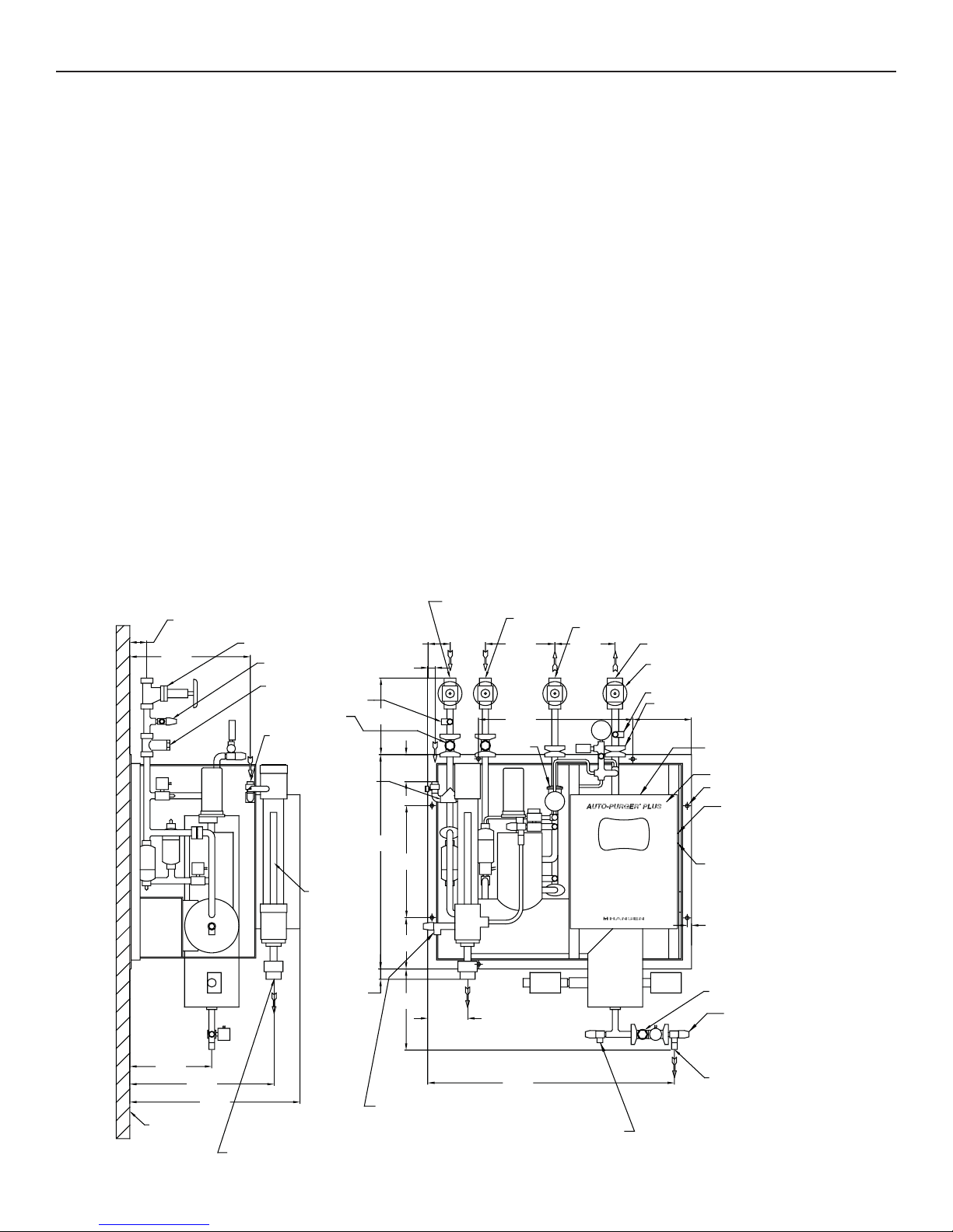
AUTO-PURGER PLUS APP INSTALLATION DIMENSIONS
Figure 1
1/2" FPT FOUL GAS LINE CONNECTION FROM PURGE POINTS
2.50" [64 MM]
16.25"
[413 MM]
SHUT-OFF VALVE
1/4" FPT GAUGE VALVE
1/2" STRAINER
1/4" FPT GAUGE VALVE
1/2" STRAINER
1/2" FPT WATER
BUBBLER FILL LINE
SHUT-OFF VALVE
CONNECTION
1/2" WATER LINE
FLOW REGULATOR
BUBBLER
12.00"
[305 MM]
31.50"
[800 MM]
3.62"
[92 MM]
1.50"
[38 MM]
[114 MM]
16.50"
[419 MM]
ON HIGH PRESSURE CONDENSERS AND RECEIVERS
4.50"
FOUL GAS PIPING
It is nearly impossible to predict where noncondensible
gases (air) will accumulate. Therefore, purging at several
points on the high-pressure side of the system is the best
method for removing air from the system.
For multipoint purgers, the solenoid valves may be
manifolded into one line to the purger. However, only one
purge point should be purged at a time. Connecting two
purge points together may result in gas flowing from one
condenser to another due to unequal pressure drop, even
though the difference in pressure drops is very small,
for example ¼ psi (0.02 bar). The result is that even in
the best of circumstances, only one point is effectively
purged. The best practice is to purge each condenser
and receiver circuit separately.
It is extremely important to install purge points at locations
sure to be liquid free. Also, no liquid traps are desirable
either before or after purge point solenoid valves. See
Figure 2. The line from the purge point on the condenser
to the AUTO-PURGER Plus should not pass through cold
areas where further condensing of the saturated gas can
occur. If this cannot be avoided, the purge line must be
insulated because flooded purge point lines will flood the
AUTO-PURGER Plus with liquid, resulting in a temporary
halt of noncondensibles being removed.
4.19"
[106 MM]
1/2" FPT LOW-PRESSURE PUMPED-LIQUID LINE CONNECTION
10.00"
[254 MM]
21.50"
[546 MM]
RELIEF VALVE
3/4" FPT
OUTLET
1/2" FPT LOW-PRESSURE LIQUID-RETURN LINE CONNECTION
8.94"
[227 MM]
1" FPT SUCTION LINE CONNECTION
TO PROTECTED SUCTION ACCUMULATOR
SHUT-OFF VALVE
1/4" FPT GAUGE VALVE
FLANGE UNION
8.62"
[219 MM]
DO NOT PUNCH ELECTRICAL
ACCESS HOLES IN THE TOP
CONTROL CABINET
.53" [14 MM] MOUNTING
HOLE (TYPICAL)
.50" [12 MM] CONDUIT KNOCKOUT
FOR POWER CONNECTION
.75" [19 MM] CONDUIT KNOCKOUT
FOR REMOTE PURGE
POINT SOLENOID VALVE
CONNECTIONS
12.00"
[305 MM]
21.25"
[540 MM]
25.00"
[635 MM]
WALL OR
COLUMN
1" PVC OR 1" FPT WATER BUBBLER
DRAIN CONNECTION.
DO NOT INSTALL SHUT-OFF VALVE
IN WATER BUBBLER DRAIN LINE.
DO NOT RUN LINE MORE
APP-001b
APR 2007
THAN 10' (3 M) ABOVE BUBBLER.
7.50"
[191 MM]
1.00"
11.00"
[25 MM]
[279 MM]
HIGH PRESSURE SEPARATOR
OIL DRAIN CONNECTION (1/4" FPT)
5.75"
[146 MM]
35.00"
[889 MM]
LOW PRESSURE SEPARATOR
OIL DRAIN CONNECTION (1/4" FPT)
2
.63"
TYPICAL
[16 MM]
1/2" STRAINER
WATER PURGE LINE
SHUT-OFF VALVE
1/4" MPT CONNECTION
FOR WATER PURGE LINE
TO CUSTOMER SUPPLIED CONTAINER
The minimum line size for foul gas piping is ½” (13 mm).
The line should be pitched down toward the purger to
drain any refrigerant that may condense.
It is important that one purge point solenoid valve is
open at all times to prevent losing foul gas pressure to
the purger. The high side pressure transducer monitors
foul gas pressure and the AUTO-PURGER Plus will enter
an alarm condition if foul gas pressure is lost.
EVAPORATIVE CONDENSER PIPING
Typically, ammonia evaporative condenser outlet liquid
drain lines on each circuit must drop between 4’–6’ (1.2m–
1.8m) from the centerline of the condenser outlet to the
centerline of highest elevation of the liquid line manifold
to receiver. Preferably each circuit should have a P-trap
to balance variations in pressure drop in each circuit
and to prevent liquid from backing up into one or more
condensers, flooding the purge point. A properly-sized
equalizer line from the receiver will help drain condenser
circuits into the receiver. Refer to ASHRAE guidelines or
IIAR papers on condenser piping design. Also, consult
condenser manufacturer’s installation instructions for
additional piping and sizing information.
Do not use one purge point solenoid valve to purge two
circuits. This negates the P-trap on the condenser drain
line and may back liquid up into one circuit.
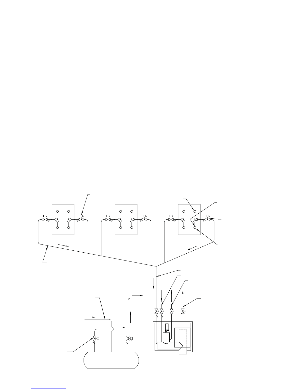
PURGE POINT LOCATIONS
Co n dens e r s sho uld b e pur g e d at point s reco mmend ed by
the condenser manufacturer. This is typically at the top
of each circuit’s outlet header.
In some cases a small, high-pressure auxiliary receiver
is located at the outlet of one or more condensers. This
receiver should have a purge point at the top.
Where a high-pressure float regulator is used to drain one
or more condensers, the top of the float valve chamber
should be a purge point.
Heat exchangers and horizontal shell and tube water-
co oled c onde n sers s h ould be pu r ged a t the top , usu a lly a t
the point or points furthest from the compressor discharge
main inlet. Vertical condensers should be purged near the
top of the vessel if possible.
For certain types of oil separators where very low velocities
may exist near the top of the vessel, purging may be
advisable from a top fitting.
It is not necessary to purge control pressure receivers,
high pressure thermosyphon vessels, or vessels located
on the low side of the system.
1/2" (13 MM) PORT
PURGE POINT
SOLENOID (TYPICAL)
CONDENSER CONDENSER CONDENSER
PITCH FOUL GAS LINES TOWARD PURGER
1/2" (13 MM) LINE SIZE UP TO 200–300 FEET (60–90 M)
3/4" (20 MM) LINE SIZE FOR LONG PURGE GAS LINES
OR WHERE TWO PURGERS ARE PURGING A
COMMON PURGE POINT
LIQUID DRAIN LINE FROM CONDENSER
TYPICAL PURGE POINT LOCATIONS
Figure 2
CONDENSER
INLET (TYPICAL)
(NO TRAPS
A
L
LOWED)
FOUL GAS LINE TO PURGER
1/2" (13 MM) LOW-PRESSURE PUMPED-LIQUID LINE
1/2" (13 MM) LOW-PRESSURE LIQUID-RETURN LINE
PURGE POINT CONNECTION ON
TOP OF OUTLET PIPE OF EACH
CIRCUIT IN CONDENSER (TYPICAL)
PURGE POINT SOLENOID VALVE
(TYPICAL). LOCATE SOLENOID
VALVE NEAR THE PURGE POINT
AT THE SAME OR HIGHER
ELEVATION THAN THAT
OF THE PURGE POINT
CONDENSER OUTLET (TYPICAL)
3/4" (20 MM) MINIMUM SUCTION LINE TO
PROTECTED SUCTION ACCUMULATOR
PURGE POINT SOLENOID
VALVE (TYPICAL)
RECEIVER
AUTO-PURGER PLUS APP (ALL MODELS)
3
APP-001b
APR 2007
LOW-PRESSURE PUMPED-LIQUID LINE
A ½” (13 mm) low-pressure pumped-liquid source is
required for the AUTO-PURGER Plus. This connection
should be from the pump discharge of the lowest pressure
rec ircul ator. S ee Fi gure 3 . Thi s con necti o n sho uld b e at a
location where oil will not be directed into the purger. The
low-pressure pumped-liquid line feeds makeup liquid as
required during purging. The line contains liquid ammonia
that typically is also contaminated with water which is to
be removed by the AUTO-PURGER Plus. The liquid line
solenoid valve (B) on the AUTO-PURGER Plus closes when
the AUTO-PURGER Plus is off. See Figure 4.
If the system contains more than one vessel that does not
feed liquid to any other lower pressure vessel, then separate
pipes may need to be installed, with corresponding shutoff valves, so that liquid can periodically be drawn from
each vessel which may contain water. The liquid pressure
must be a minimum 15 psi (1.0 bar) higher than the APP
suction for the liquid to feed properly.
LOW-PRESSURE LIQUID RETURN LINE
A ½” (13 mm) low-pressure liquid return line is required
for the AUTO-PURGER Plus. Ammonia vapor from the
foul gas line is condensed to liquid in the air separator
chamber. This condensed liquid ammonia flows to the
suction accumulator through the low-pressure liquid
return line. See Figure 3.
SUCTION LINE
A ¾” (20 mm) suction line should be connected to a
suction accumulator. See Figure 3. The purger evaporator
shell temperature sensor is factory set at 40°F (4°C). To
allow for temperature transfer losses between the purger
evaporator and the temperature sensor, the suction
temperature should be approximately 20°F (–7°C) or
below. This then switches the AUTO-PURGER Plus from
its PURGER COOLING DOWN mode to its COLLECTING
AIR AND WATER mode. For higher suction temperatures,
consult the factory.
WATER BUBBLER FILL LINE
An automatic water bubbler flush system is provided with
the purger. A water line must be connected to the water
bubbler fill line solenoid valve (D). See Figure 4. The
connection is ½” FPT. The water supply pressure should
be 30–80 psig (2.1–5.5 barg).
The clear tube of the water bubbler may become coated
with mineral deposits after a period of time. These deposits
can be removed by adding a cup of vinegar to the water
in the bubbler and cleaning the clear tube through the top
plastic fitting with the supplied brush. A water conditioning
filter housing and cartridge are available for abnormally
hard water.
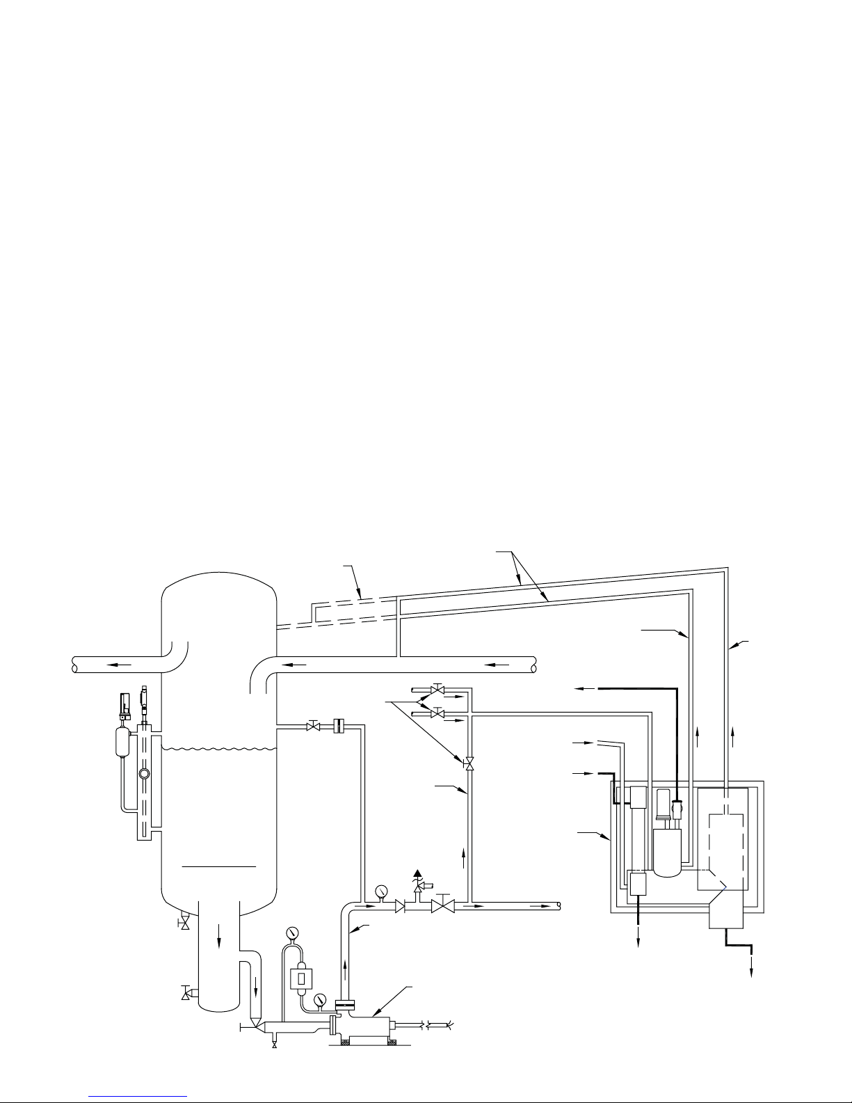
AUTO-PURGER PLUS APP PIPING DIAGRAM
Figure 3
PITCH LINES TOWARD
OPTIONAL
PIPING
TO COMPRESSORS FROM EVAPORATORS
SHUT-OFF VALVES
TO SWITCH FROM
MULTIPLE VESSELS
LOWEST PRESSURE
RECIRCULATOR
RECIRCULATOR
PUMPED
LIQUID LINE
RELIEF VALVE
VENT LINE
FOUL GAS LINE
FROM PURGE POINTS
WATER BUBBLER
FILL LINE
AUTO-PURGER
PLUS
TO SYSTEM
LOW PRESSURE
LIQUID RETURN LINE
SUCTION
LINE
APP-001b
APR 2007
PUMP
DISCHARGE
LINE
REFRIGERANT PUMP
WATER BUBBLER
DRAIN LINE
WATER PURGE
LINE
This drawing is for illustration purposes only
and should not be used for actual engineering
or installation. Not to scale.
4

WATER BUBBLER DRAIN LINE
A 1” (25 mm) PVC socket/1” FPT water drain connection
is located at the bottom of the bubbler. The water bubbler
drain line should flow to a suitable drain or container. See
Figure 4. If the drain line is run overhead, the fitting on the
top of the water bubbler must be sealed, including the ¼”
NPT vent connection in the fitting, and a protective mesh
installed around the clear tube. Do not run the line more
than 10’ (3 m) above the height of the bubbler because the
pressure on the water bubbler could be excessive. Support
the drain line to prevent undue stress on the water bubbler.
Also, do not install a shutoff valve in this line.
Initially, fill the water bubbler with water through the 3”
(80 mm) plug located on top of the tube. Keep the plug
lubricated and hand tight. Check for leaks at the hose
fittings.
WATER PURGE LINE
Water removed from the refrigeration system by the
AUTO-PURGER Plus flows out the water purge line. This
line should be directed to a customer supplied container,
such as a 55 gallon drum for example. See Figure 4. It is
recommended to use rigid metal tubing or to secure the
line. Commonly, when draining water initially all the water
is released, then any oil is released, and then a small
quantity of ammonia vapor may be released. A loose hose
may whip around when the last of the liquid slugs come
out of the hose and is therefore not recommended. The
customer supplied container may be partially filled with
water, and the end of the water purge line submerged in
this water so that any small amount of ammonia vapor
that may be released is dissolved in this water.
OIL DRAINS
Excess oil can reduce the purger capacity by lowering
the evaporating or condensing rate. Oil is not typically a
problem. Oil in the evaporator chamber is typically released
with the water that is released out the water purge line.
However, any oil that may collect in the purger can be
drained off through the two capped ¼” valves on the purger.
See Figure 1. Before draining oil, close the foul gas and
low-pressure pumped-liquid valves. Allow the purger to
pump out, then close the low-pressure liquid return and
suction line valves. Use normal oil draining precautions
to prevent injury or property damage.
AUTO-PURGER Plus models APP08, APP16, and APP24
have an additional ¾” (20 mm) knockout for individual
purge point solenoid valves. Wires from each purge point
solenoid valve should be brought to the purger control
cabinet. Any additional access holes should be made on
the side of the control cabinet. All access holes into the
control cabinet must be sealed to prevent moisture, dust,
and debris entering the cabinet.
From each purge point solenoid, one wire is connected
to the corresponding screw terminal for the purge point
inside the control cabinet on the terminal strip. For 115VAC
models, the other wire from the purge point solenoid is
connected together for all the purge points and tied to the
available neutral position on the top terminal strip. For
the 220VAC models, the other wire from the purge point
solenoid is connected together for all the purge points
and tied to the top terminal strip labeled PP_COM.
Models APP08, APP16, and APP24 supply 115VAC to the
purge points rega rdless of wh ether 115VAC or 220VAC is
supplied to the control cabinet.
All APP models have a relay available which energizes
whenever action is required by plant personnel. The
no r mally open conta c ts wi ll c l ose w hen a ction is r e quire d.
If desired, the contacts may be connected to a light, an
audible alarm, or to a plant computer, to notify plant
personnel to attend to the purger. The contacts are rated
for 10 amps. Connection to the relay is made at the top
terminal strip labeled REMOTE RELAY.
LEAK TEST
Use standard refrigeration procedures to check the
AUTO-PURGER Plus for leaks before placing it in service.
To confirm a leak-free AUTO-PURGER Plus, manually
open one remote purge point solenoid valve, if there is
one. Manually open the foul gas shut-off valve and allow
pr e s sure insid e the purg e r to buil d to conde nsing press u re,
as shown on the high side pressure gauge. Then, manually
op e n the hig h side to l ow s ide b ypass valve to pres s uriz e
the evaporator section of the purger, as shown on the low
si d e pr e s sure g auge . See Figu r e 4. C heck for l eaks . Clos e
the high side to low side bypass valve.
ELECTRICAL CONNECTIONS
The standard AUTO-PURGER Plus requires a 115V 50/60Hz
17 amp electrical supply on a 20 amp circuit breaker;
models for 220V 50/60Hz, 11 amps electrical supply on
a 15 amp circuit breaker are available. All models have a
½” (13 mm) knockout on the side of the control cabinet to
access the power connection terminal strip. Any unused
knockout holes must be sealed to prevent splashing water,
dust, and debris from entering the control cabinet. After
completing all electrical connections inside the cabinet,
connect the cable from the PLC Control Console to the
PLC. Connect the cable plug to the socket and tighten the
hand screws. Refer to the wiring tag inside unit.
5
APP-001b
APR 2007

SECTION 3 AUTO-PURGER PLUS OPERATION
The AUTO-PURGER Plus is designed to automatically start-
up and operate without the assistance of plant personnel.
Beginning at start-up, the following is a description of
the refrigerant flow through a purger when all connecting
shut-off valves are open. See Figure 4.
START-UP
Make sure all piping, electrical connections, and settings
are complete as described in this bulletin. Open the foul
gas, low-pressure pumped-liquid, low-pressure liquid
return, and suction line shut-off valves. Open the purge
gas valve. The water purge line shut-off valve should
remain closed at this time (open only while draining
water). On start-up, the AUTO-PURGER Plus enters a
COOLING DOWN stage. (The display indicates 3333.) In
this stage, liquid refrigerant fills and cools the purger.
The low-pressure pumped-liquid line solenoid valve (B)
energizes to feed refrigerant to the low-pressure flooded
evaporator. The liquid make-up level sensor, located in the
evaporator chamber, senses when the flooded evaporator
is full and closes the low-pressure pumped-liquid line
solenoid valve (B).
At the same time the flooded evaporator is cooling, the
control software energizes the first purge point solenoid
valve. Foul gas enters the high-pressure air separator
chamber and condenses to fill the high-pressure air
separator chamber with liquid. When the float switch
chamber fills with liquid refrigerant, the float ball rises
and pulls in the float switch magnet.
At approximately 20°F (–7°C) evaporator temperature,
the evaporator shell temperature sensor switches the
purger from the COOLING DOWN stage to STARTUP
DELAY MODE for 10 minutes, as indicated by the Control
Console no longer displaying 3333. The control software
will not allow any noncondensibles into the water bubbler
until 10 minutes after the Control Console discontinues
indicating 3333.
OPERATION
When the purger is in COLLECTING AIR AND WATER mode,
a mixture of noncondensible gas and refrigerant flows
into the purger. The evaporator shell temperature sensor
also allows solenoid valves (C) and (D) to open when the
float ball is down (magnet away from tube).
The foul gas may carry a certain amount of condensed
refrigerant, which is captured by the liquid drainer before
it enters the purger’s condenser coil. From the liquid
drainer, the liquid is fed directly into the low-pressure
li quid r etur n lin e. If this separ a tion does not o ccur, l iqui d
refrigerant will fill the purger’s condenser and limit the
condensing capacity of the purger.
The liquid-free foul gas enters the purger condensing
coil, which is submerged in the flooded evaporator. The
refrigerant condenses inside the coil. The condensed
refrigerant and noncondensible gas then flow through a
check valve and back into the air separator chamber. The
condensed liquid refrigerant is removed from the high-
pressure air separator chamber through the liquid metering
valve and to the low-pressure liquid return line.
Meanwhile, the noncondensible gas travels along the top of
the air separator chamber and into the float ball chamber
where it collects. As more noncondensible gases collect,
APP-001b
APR 2007
the liquid level gradually falls, causing the float ball to
fall. This changes the SPDT switch position of the liquid
level float switch and energizes the purge gas solenoid
valve (C) and the water bubbler fill line solenoid valve (D),
allowing noncondensible gas to bleed through the orifice
plate into the water bubbler. As air is released into the
water bubbler, the liquid refrigerant level in the purger
float ball chamber rises.
The control software operates each specified remote
purge point solenoid valve in sequence.
The make-up liquid from the low-pressure pumped
liquid line typically contains a small percentage of water
dissolved in the liquid ammonia. This is the water the
AUTO-PURGER Plus will remove from the refrigeration
system. Liquid ammonia and water are brought into the
evaporator chamber of the purger, but only ammonia
vapor can exit through the suction line. Gradually
the concentration of water in the evaporator chamber
increases with time. When the concentration of water in
the evaporator chamber reaches about 25% water / 75%
am m onia , as de tecte d by the wate r con centr a tion senso r,
the AUTO-PURGER Plus switches to the CONCENTRATING
WATER mode. The purger stops collecting air, isolates
the mixture of water and ammonia, and energizes the two
electric heaters. About half the energy to concentrate
the water comes from the two electric heaters, and the
other half comes from the foul gas that continues to flow
through the purger. The heaters remain energized until the
ammonia water solution is heated to 185°F (85°C), except
for suction pressures in a vacuum. This corresponds to a
concentration of about 10% to 20% ammonia and about
80% to 90% water. In a vacuum, water boils at lower
temperatures, so the set point to which the ammonia
water solution is heated is reduced to an appropriately
lower temperature depending on the suction pressure as
detected by the low side pressure transducer.
The AUTO-PURGER Plus will prepare the concentrated
water for draining, but the computer software will not
allow draining until an operator presses a button to permit
draining. The suction line solenoid valve (E) shuts. The
Control Console indicates READY TO DRAIN. OPEN WATER
PURGE SHUT-OFF VALVE THEN PRESS “OK” BUTTON.
The system remains in this condition until an operator
opens the water purge line shut-off valve and presses the
OK button on the Control Console. See Figure 5.
6
 Loading...