

Hansen AUTO-PURGER M, APM, APMF Service Instructions Manual
Specifications, Applications,
Service Instructions & Parts
Compact, Non-condensible
For Models APM & APMF
Model APM
SECTION 1 MOUNTING & PIPING INSTALLATION
Bulletin APM-001e
AUG 2015
AUTO-PURGER® M
“Energy Saver”
Gas (Air) Purger
INTRODUCTION
The AUTO-PURGER® M is a compact and totally automatic,
electronically-controlled, noncondensible gas refrigerant
purger for reducing condensing pressure, and thereby
saving electrical energy used by the refrigeration system.
This deluxe purger is preassembled, prewired, tested,
insulated, and includes an automatic water bubbler.
Installation requires piping the foul gas line, liquid line,
suction line, water line, drain line, and wiring the power
connection and the remote ½" (13 mm) port purge point
solenoid valves, which must be purchased separately. Up
to four (4) purge points can be controlled by this purger.
The AUTO-PURGER® M (APM) features welded piping
and watertight electrical construction. The APM meets
the requirements of the Canadian Standards Association
(CSA certified).
A typical APM installed in a plant with normal-entering
noncondensible loads will handle up to a 200 ton (700 kW )
system. Each purge point will be active between 10 and 30
minutes, depending on the noncondensible gas presence
(mostly air) and the purger mode of operation.
Model APMF AUTO-PURGERS are for use in halocarbon
refrigeration systems. The installation and operation of
these AUTO-PURGERS are similar to that of an ammonia
AUTO-PURGER M. See page 13 for additional details.
MOUNTING INSTRUCTIONS
Mount the APM straight and securely on a wall or sturdy
steel channels capable of supporting 350 lbs (160 Kg). Eight
mounting holes in the frame are provided to support the
purger (See Figure 1). The APM should be located in an
accessible area, but away from the movement of equipment
that could accidentally damage the purger. Elevation with
respect to condensers or high-pressure receivers is not
critical, however, purge point solenoid valves must be
above the purger.
An APM is usually installed in the compressor room where
it can be monitored, but also may be installed outdoors
where temperatures below freezing are not anticipated.
The APM comes standard with a watertight NEMA 13 (IP65,
Category 2) control cabinet enclosure with sealed conduit
wiring. Any unused electrical entrances to the enclosure
must be sealed to protect electronics from moisture. A
NEMA 4 cabinet enclosure is available.
An optional valve package (VPM) for purger isolation is
available from Hansen. This consists of three welded
assemblies which include shut-off valves, gauge valves,
and mating flanges. An illustration detailing this optional
valve package is on page 12 (Figure 13).
FOUL GAS PIPING
Purging at several points, up to four with the APM, on the
high-pressure side of the system is the best method for
removing foul gas. Foul gas is refrigerant gas containing
some air or other noncondensibles. Several points should
be used because it is nearly impossible to predict where
noncondensible gas will accumulate in a system.
Even for multipoint purging, only one purge point should be
purged at a time. Connecting two purge points from two
condensers or receivers may result in gas flowing from one
condenser to another. This is due to an unequal pressure
drop, even though the differences in pressure drop are
very small, for example ¼ psig (0.02 bar). The result would
be that, even in the best of circumstances, only one point
is effectively purged. The best practice is to purge each
condenser and receiver circuit separately.
When utilizing multipoint purging, the purge point solenoid
valves can be manifolded into one foul gas line to the
purger. A ½" (13 mm) size line is the minimum and should
be pitched toward the purger to drain any condensed
liquid. Also, no liquid traps are allowed either before or
after the purge point solenoid valves (See Figure 2). The
foul gas line should not pass through cold areas where

ACTIVE PURGE POINT
1234
ENERGY SAVER
R
HANSEN TECHNOLOGIES
CORPORATION
(25)
(298)
ON HIGH PRESSURE CONDENSERS AND RECIEVERS
PROTECTED SUCTION ACCUMULATOR
(24)
(86)
(192)
TYPICAL
(16)
(508)(813)
(152)
FOR POWER CONNECTION
FOR REMOTE PURGE POINT
SOLENOID VALVE CONNECTIONS
(86)
(359)
(49)
(457)
OIL DRAIN CONNECTION (3/8" FPT)
OIL DRAIN CONNECTION (3/8" FPT)
TYPICAL
(16)
(14)
MOUNTING HOLE
8 PLACES
(59)
(130)
(178)
SHUT-OFF VALVE CONNECTION
PRESSURE RELIEF VALVE
(406)
(464)
CONNECTION
1" PVC DRAIN
WALL OR COLUMN
18.25"
BUBBLER
CONTROL CABINET
1/2" CONNECTION FOR OPTIONAL
1/2" FPT WATER LINE
7.00"
3/4" SUCTION LINE
5.11"
0.53" DIA
0.62"
18.00"
HIGH PRESSURE SEPARATOR
LOW PRESSURE SEPARATOR
1.93"
14.13"
3/4" CONDUIT KNOCK OUT
1/2" CONDUIT KNOCK OUT
6.00"
32.00"
20.00"
0.62"
3/4" SUCTION LINE CONNECTION TO
1/2" HIGH PRESSURE LIQUID LINE CONNECTION
1/2" FOUL GAS'' LINE CONNECTION FROM PURGE POINTS
''
3.38"
16.00"
2.31"
1.00"
0.94"
3.38"
7.56"
11.75"
1.63" (41 MM)
FROM FOUL GAS SOURCE
CLOSE-COUPLED
ISOLATION
TO PURGER
1/2" (13 MM) PORT
SHUT-OFF VALVE
REMOTE PURGE POINT
SOLENOID VALVE
ISOLATION SHUT-OFF VALVE
STRAINER
(GLOBE VALVE STEM HORIZONTAL
IS PREFERRED)
LEVEL OR
PITCH DOWN
SECTION 1 MOUNTING & PIPING INSTALLATION
further condensing of the saturated gas can occur. If this
cannot be avoided, the line must be insulated because
flooded purge point lines result in flooding the APM with
liquid, causing a temporary halt of noncondensibles
being removed. If flooding can not be avoided, additional
condensate drainage may be necessar y.
It is important that all purge points be located above any
liquid surfaces to avoid drawing liquid refrigerant, rather
than vapor, into the APM.
EVAPORATIVE CONDENSER PIPING
Typically, evaporative condenser outlet liquid drain lines
on each circuit must drop a minimum of 4 feet (1.2 m) for
ammonia from the centerline of the evaporative condenser
outlet to the centerline of highest elevation of the liquid
line manifold to receiver. Preferably, each circuit should
INSTALLATION DIMENSIONS (MM)
Figure 1
have a P trap to balance variations in pressure drop in each
circuit to prevent liquid from backing up into one or more
condensers, and thereby flooding the purge point. Most air
from the system will normally be trapped between the
condenser and the P trap. Also, a properly-sized equalizer
line from the receiver will help drain condenser circuits
into the receiver. Refer to ASHRAE GUIDELINES or IIAR
Papers on condenser piping design. Hansen Technologies
can provide copies of these articles. Also, consult the
condenser manufacturers’ installation instructions for
additional piping and sizing information.
On evaporative condensers, avoid using one purge point
solenoid valve to purge two circuits. This practice negates
the P-trap on the condenser drain line because of the
purge connections of the two circuits and may back liquid
up into one circuit.
APM-001e
AUG 2015
2
FROM FOUL GAS SOURCE
CLOSE-COUPLED
ISOLATION
TO PURGER
1/2" (13 MM) PORT
SHUT-OFF VALVE
REMOTE PURGE POINT
SOLENOID VALVE
ISOLATION SHUT-OFF VALVE
STRAINER
(GLOBE VALVE STEM HORIZONTAL
IS PREFERRED)
LEVEL OR
PITCH DOWN
SECTION 1 MOUNTING & PIPING INSTALLATION
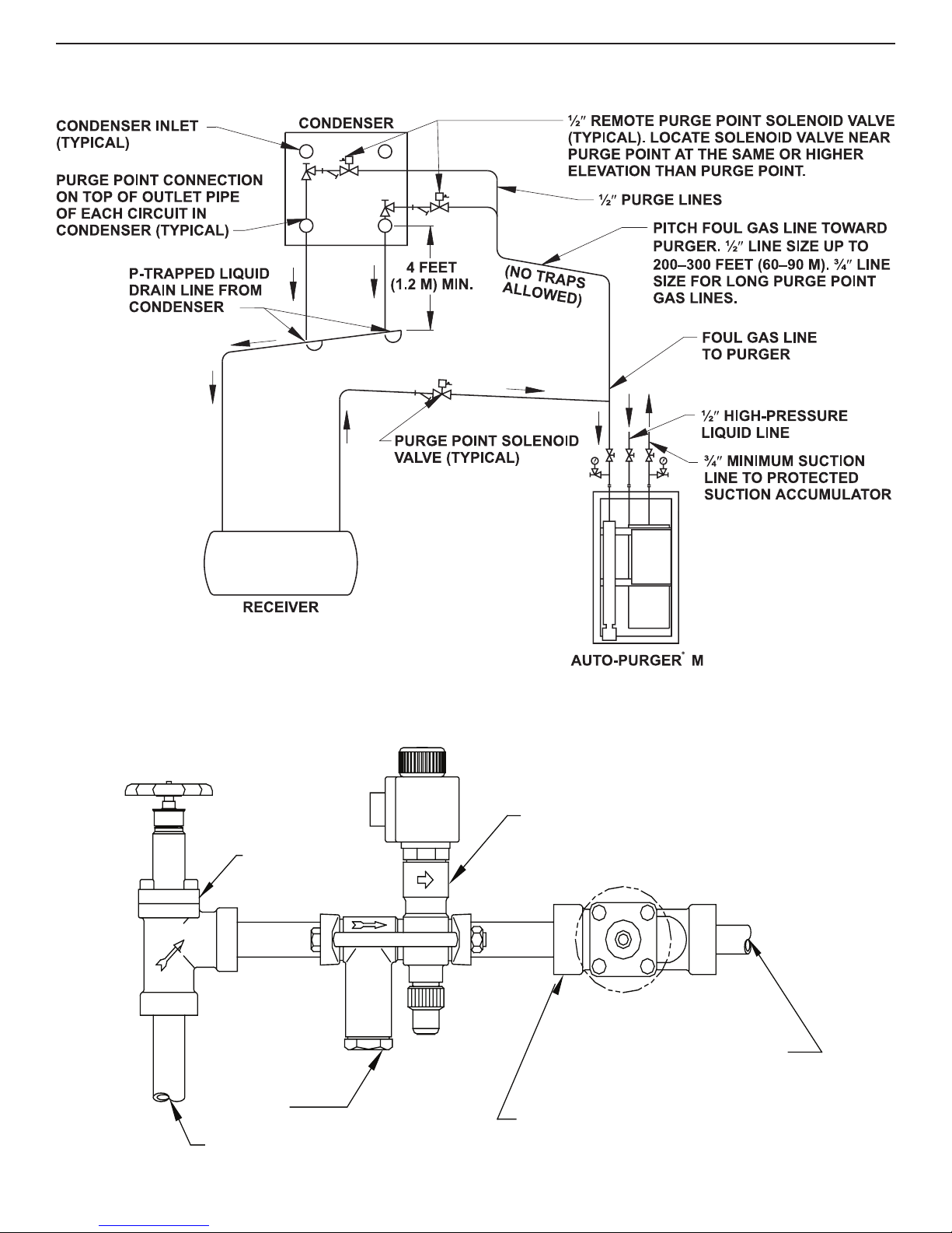
TYPICAL APPLICATION
Figure 2
PURGE POINT VALVE (TYPICAL)
Figure 3
3
APM-001e
AUG 2015

SECTION 1 MOUNTING & PIPING INSTALLATION
PURGE POINT CONNECTIONS
Foul gas lines from condensers should be purged at points
recommended by the condenser manufacturer. Usually, this
is at the top of each circuit’s outlet header which drains
down through a P-trap to the receiver. In some cases, a
small high pressure auxiliary receiver is located at the
outlet of one or more condensers. This receiver should
have a purge point at the top, preferably at a “dead” area
away from condenser drain pipes. Below is a typical valve
arrangement for a purge point (Figure 3). Regardless of
the purge point location, it is absolutely necessary to
ensure that liquid is not drawn into the foul gas line.
Where a high-pressure float regulator is used to drain one
or more condensers, the top of the float valve chamber
should also be a purge point.
Horizontal shell and tube water-cooled condensers, and
heat exchangers should be purged at the top, usually at
the point(s) fur thest from the compressor discharge main
inlet.
Vertical condensers should be purged near the top of the
vessel if possible.
For certain types of oil separators where very low velocities
may exist near the top of the vessel, purging may be
advisable from a top fitting.
It is normally not advisable to purge controlled pressure
receivers, high-pressure thermosyphon vessels, or vessels
located on the low side of the system.
SUCTION LINE
The ¾” suction line from the purger should be connected
to a protected main suction line or a suction accumulator.
Install a suction line isolation shut-off valve near purger.
Excess amounts of liquid from the purger evaporator may
occasionally be transmitted through the suction line. The
suction temperature must be 40°F (4.4°C) or less to satisfy
the APM temperature sensor before purging will occur.
LIQUID LINE
A high-pressure ½” liquid line is required for the APM. The
connection to the high-pressure liquid source should be
a location where oil will not be directed into the purger.
Install liquid line shut-off valve near the purger. The liquid
line supplies refrigerant during start-up and feeds makeup liquid as required. The only requirement is the liquid
supply pressure must be sufficiently above the purger
evaporator pressure, usually greater than 60 psi (4.1 bar).
During operation, only 5% of the liquid refrigerant required
for cooling comes from the liquid line. The remainder of
the refrigerant is condensate from the foul gas line, which
is collected in the drain, condensed in the coil, and into
the evaporator.
WATER LINE
The APM has an automatic water bubbler to eliminate any
water bottle attention. Connect the water supply to the
purger water shut-off valve (See Figure 1). Water pressure
should be between 30 and 80 psig (2 and 5 bar). The
factory-installed flow controller limits the amount of water
going into the bubbler.
The transparent tube of the water bubbler may become
coated with mineral deposits after a period of time. These
deposits can be removed by adding a cup of vinegar to the
water in the bubbler and cleaning the clear tube through
the top plastic fitting with the brush supplied. A water
conditioning filter cartridge and housing are available for
abnormally hard water.
DRAIN LINE
A 1” PVC socket water drain connection is located at the
bottom of the bubbler (an alternate 1” FPT threaded adapter
is also supplied). The water should flow to a suitable drain.
Initially, fill the water bubbler with water via the threaded
plug located at the top of the bubbler. Keep the plug
lubricated and hand tight. A circular, thin, plastic “stickon” acts as a bubbler relief device in case of water drain
plugging. The drain line should be supported to prevent
undue stress on the water bubbler.
OIL DRAINS
There are two 3/8” valve oil drain connections near the
bottom of purger (see Figure 1) from which oil can be
drained. These valves are fitted with 5/16” (8 mm) hex
socket plugs. Before draining oil, first close the liquid and
foul gas lines to prevent additional liquid from entering the
purger. Wait approximately one half hour and then turn
the purger off. Allow the purger to pump out, then close
the suction line shut-off valve. Use normal refrigerant oil
draining precautions to prevent human or property damage.
In general, oil will not be a problem unless the liquid line
is connected to a vessel or line where oil can enter the
purger. See also the Caution section on page 14. Escaping
refrigerant may cause personal injury, particularly to the
eyes and lungs.
LEAK TEST
Use standard refrigeration procedures to check the APM
for leaks before placing it into service. See also the
Caution section on page 14. Manually open one purge
point solenoid valve. Open the foul gas line shut-off valve
and wait a few moments for the flooded evaporator to
pressurize through the metering orifice. Allow pressure to
build to condensing pressure, as shown on the high side
pressure gauge. Close the foul gas line shut-off valve and
check the purger for leaks.
APM-001e
AUG 2015
4
SECTION 2 ELECTRICAL INSTALLATION & OPERATION
PRESSURE TRANSDUCER
P
P
CONTROL BOAR
TEMPERATURE SENSOR
PURGE POIN
CABL
S
POWER BOARD
REMOTE PURGE POINT SOLENOID
ELECTRICAL CONNECTIONS
The standard electrical requirement for the APM is 115V
50/60 Hz. Also available is 230V 50/60 Hz. Main supply
voltage fluctuations should not to exceed ± 10% on nominal
voltage. Connect APM to a dual pole external switch or
circuit breaker suitable for full disconnection. Locate this
switch or circuit breaker nearby. The control cabinet has
a bottom ½” knockout for power connection and bottom
3/4” knockout for individual purge point solenoid valves
(See Figure 4). Any additional knockouts, if necessary,
should be made on the bottom of the control cabinet. A
grounding block inside the control cabinet is provided for 3
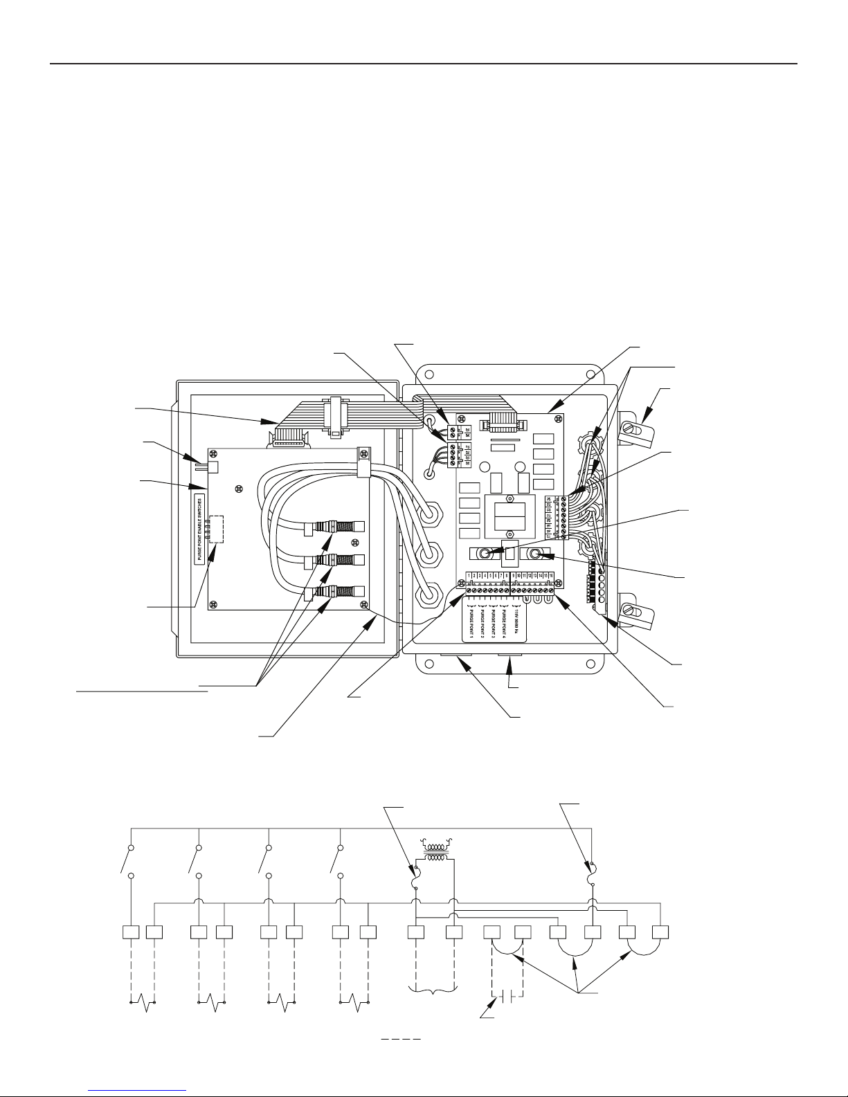
CONTROL CABINET (INSIDE VIEW)
Figure 4
PLUG-IN CONNECTOR
E
RESET PINS
CONTROL BOARD
AND SHIELD
D
1
wire purge point solenoid coils. Carefully study the wiring
diagram below (Figure 5) to avoid electrical short circuits.
Connect electrical wiring from each purge point solenoid to
the remote purge point solenoid plug-in connector screw
terminals (1 through 8) plus the grounding block. Normally,
the voltage of the remote purge point solenoid valves is the
same as the purger. However, if the purge point solenoid
valve coil voltage is different, simply remove and discard
the factory installed jumpers between terminals 13 & 14 and
15 & 16. Bring the purge point solenoid line (L1) connection
to terminal 14 and neutral (L2) to terminal 16.
PLUG-IN CONNECTOR
F6A
F6B
POWER BOARD
RTV SILICONE SEALANT
CONTROL BOX LATCH
PURGER SOLENOID
PLUG-IN CONNECTOR
REMOTE PURGE
POINT SOLENOID
REPLACEABLE 3 AM
FUSE (P/N 20-1698)
ENABLE SWITCHES
T
COAXIAL CONNECTORS
1-DRAINER LEVEL SENSOR
2-LOW SIDE LEVEL SENSOR
3-HIGH SIDE LEVEL SENSOR
GROUNDING WIRE
#1 #2 #3 #4
#1
PURGE POINT SOLENOID VALVES
#2 #3 #4
2
POWER BOARD
REPLACEABLE 3 AM
3
REMOTE PURGE
POINT SOLENOID
PLUG-IN CONNECTOR
NLLLN NNLLN
1/2'' KNOCKOUT
3/4'' KNOCKOUT
FUSE (P/N 20-1698)
GROUNDING BLOCK
POWER / INTERLOCK
PLUG-IN CONNECTOR
WIRING DIAGRAM
Figure 5
POWER BOARD REPLACEABLE
3 AMP TYPE F FUSE (P/N 20-1698)
LINE
NEUTRAL
LINE VOLTAGE
OPTIONAL INTERLOCK
(REMOVE JUMPER IF USED)
FIELD INSTALLED WIRING
5
REPLACEABLE 3 AMP TYPE F FUSE
(P/N 20-1698)
16151413121110987654321
FACTORY-INSTALLED JUMPER
APM-001e
AUG 2015
 Loading...