

Hansen P4, 405 Installation Manual
Installation manual
405
Standardized gear units
Hansen Industrial Transmissions nv
IM_405
Copyright and contact data
Copyright Hansen Industrial Transmissions NV
This document or parts thereof may not be reproduced, stored in a retrieval system, nor
transmitted, in any form nor by any means, electronic, mechanical, photocopying, recording, nor
otherwise, without the prior written permission of Hansen Industrial Transmissions NV.
This document could contain technical inaccuracies or typographical errors. Hansen Industrial
Transmissions NV reserves the right to revise the content of this document from time to time
without the obligation of Hansen Industrial Transmissions NV to notify any person of such revision
or change.
Details and values given in this document are average values and have been compiled with care.
They are not binding, however, and Hansen Industrial Transmissions NV disclaims any liability for
damage or detriments suffered as a result of reliance on the information given herein or the use of
products, processes or equipment to which this document refers. No warranty is made that the use
of the information or of the products, processes or equipment to which this document refers will not
infringe any third party's patents or rights. The information given does not release the user from
making their own experiments and tests.
Contact data
www.sumitomodrive.com
Hansen Industrial Gearbox Services
Terelststraat 208
BE-2650 Edegem
Belgium
E-mail: hit.info@shi-g.com
24/7 SERVICE HOTLINE
Tel.: +32 3 450 12 34
2

Contents
Contents
1 Customer data sheet................................................................................7
2 Manual Disclaimer................................................................................... 9
3 About this document.............................................................................. 10
3.1 Function of the document.......................................................................................................... 10
3.2 Language...................................................................................................................................10
3.3 Illustrations.................................................................................................................................10
3.4 Use of steps, lists and titles in this document............................................................................ 10
3.5 How to use this document..........................................................................................................10
3.6 Warnings, cautions and notes used in the document................................................................ 10
3.7 Related documents....................................................................................................................11
3.8 Storage of this document and the related documents............................................................... 12
3.9 Abbreviations............................................................................................................................. 12
3.10 Customer support...................................................................................................................... 12
4 Description............................................................................................. 13
4.1 Intended use.............................................................................................................................. 13
4.2 Type plate.................................................................................................................................. 13
4.2.1 Type plate.................................................................................................................. 13
4.3 Signs in the documentation and on the gear unit.......................................................................14
4.4 Description of the lubrication of the gear unit.............................................................................17
4.4.1 Function of lubrication................................................................................................17
4.4.2 Splash lubrication.......................................................................................................18
4.4.3 Force-feed lubrication................................................................................................ 18
4.5 Breather plug............................................................................................................................. 18
4.6 Cooling system.......................................................................................................................... 18
4.7 Direction of rotation of the shafts............................................................................................... 19
5 Safety.....................................................................................................20
5.1 Restrictions................................................................................................................................ 20
5.2 Approved installation engineer...................................................................................................20
5.3 General safety instructions........................................................................................................ 20
5.4 Safety instructions for installation.............................................................................................. 21
5.5 Special safety instructions (backstop)........................................................................................21
5.6 Noise and vibrations.................................................................................................................. 21
5.7 Partly completed machine..........................................................................................................21
5.8 Instructions in case of a fire....................................................................................................... 21
5.9 Warranty.................................................................................................................................... 22
6 Transport................................................................................................23
6.1 Off-site transport........................................................................................................................ 23
6.2 On-site transport........................................................................................................................ 23
6.2.1 Lift the gear unit......................................................................................................... 23
IM_405_002_EN
3

Contents
7 Storage.................................................................................................. 26
7.1 General storage instructions......................................................................................................26
7.2 Indoor storage for maximum 1 year...........................................................................................26
7.3 Extended storage outdoors for maximum 2 years (extended outdoor storage).........................26
7.4 Extended storage indoors for maximum 5 years (extended indoor storage)............................. 27
8 Installation..............................................................................................28
8.1 Maximum time between installation and commissioning........................................................... 28
8.2 Remove the packaging material................................................................................................ 28
8.3 Installation instructions for parts that are not part of the gear unit.............................................28
8.4 Do a check for corrosion of internal parts of the gear unit......................................................... 28
8.5 Install the couplings................................................................................................................... 28
Prepare.......................................................................................................................................29
Apply the sealing paste.............................................................................................................. 29
Install the coupling hubs.............................................................................................................29
Remove unwanted sealing paste and apply paint......................................................................30
8.6 Install parts that give external loads to the gear unit..................................................................30
8.7 Install gear units with a backstop...............................................................................................30
8.8 Align the gear unit......................................................................................................................31
8.8.1 Align the gear unit in the horizontal plane..................................................................31
8.8.2 Align the LSS (multi-stage)........................................................................................ 31
8.8.3 Align the LSS (single stage).......................................................................................31
8.8.4 Align the HSS.............................................................................................................32
8.9 Attach the gear unit with the bolts (solid shafts)........................................................................ 32
Attach the gear unit.................................................................................................................... 32
Install the safety cover................................................................................................................32
8.10 Attach the gear unit (hollow shafts)............................................................................................32
8.10.1 Install the shrink disk..................................................................................................32
8.10.2 Install the shaft with keyway connection.................................................................... 34
8.10.3 Install the torque arm................................................................................................. 37
8.11 Install a ground connection........................................................................................................38
8.12 Install the lubrication system......................................................................................................38
8.12.1 General instructions for the lubrication system.......................................................... 38
8.12.2 Instructions for force-feed lubrication (integrated pump)........................................... 39
8.12.3 Instructions for force-feed lubrication (pump with a motor)........................................39
8.12.4 Instructions for force-feed lubrication (pressure lubrication)...................................... 39
8.13 Fill the gear unit with gear oil..................................................................................................... 39
8.13.1 Select the gear oil...................................................................................................... 39
8.13.2 Add gear oil (gear unit with motor base).................................................................... 40
8.13.3 Add gear oil (QHR.4, QVR.3 and QVR.4)..................................................................40
8.13.4 Measure the gear oil level..........................................................................................40
8.13.5 Add gear oil (all gear units)........................................................................................ 41
8.13.6 Drain gear oil..............................................................................................................41
8.14 Add grease to the lubrication points for grease......................................................................... 41
8.14.1 Select the grease type............................................................................................... 41
8.14.2 Add grease.................................................................................................................41
8.15 Install the oil-to-air cooler...........................................................................................................42
8.16 Install the water cooling............................................................................................................. 42
8.16.1 Install the water cooling............................................................................................. 42
8.16.2 Install the oil-to-water cooler...................................................................................... 42
8.16.3 Install the cooling coils............................................................................................... 43
8.17 Installation instructions (heater).................................................................................................43
4
IM_405_002_EN

Contents
9 Commissioning...................................................................................... 44
9.1 Maximum time between commissioning and operation............................................................. 44
9.2 Do a check on the gear unit.......................................................................................................44
9.3 Start instructions (backstop)...................................................................................................... 44
9.4 Start instructions (heater)...........................................................................................................44
9.5 Start instructions (force-feed lubrication, pump with a motor)....................................................44
9.6 Start instructions (force-feed lubrication, integrated pump)....................................................... 45
9.7 Start instructions (drive group with a 2-speed motor)................................................................ 45
9.8 Instructions after commissioning................................................................................................45
10 Instructions for operation....................................................................... 46
10.1 General instructions for operation..............................................................................................46
10.2 Instructions (force-feed lubrication, pump with a motor)............................................................46
10.3 Instructions (water cooling)........................................................................................................46
10.4 Instructions (drive group with a 2-speed motor).........................................................................46
10.5 Instructions if the gear unit does not operate more than 2 weeks............................................. 46
Operate the gear unit for 5 minutes each 2 weeks.....................................................................47
Protect the gear unit with a volatile corrosion inhibitor...............................................................47
11 Removal of the gear unit........................................................................48
11.1 General instructions for removal of the gear unit.......................................................................48
11.2 Remove the gear unit (solid shafts, couplings)..........................................................................48
11.3 Remove the gear unit (hollow shafts)........................................................................................ 48
11.3.1 Disconnect the gear unit from the torque reaction point............................................ 48
11.3.2 Remove the shrink disk..............................................................................................48
11.3.3 Disconnect the keyway connection............................................................................49
12 Care for the environment....................................................................... 51
13 Technical data........................................................................................52
13.1 Dimensions and mass................................................................................................................52
13.2 Materials of the gear unit........................................................................................................... 52
13.3 Torque seal specification........................................................................................................... 52
13.4 Paint specification......................................................................................................................52
13.5 Corrosion protection by H.I.T.....................................................................................................52
13.6 Position of the gear unit............................................................................................................. 53
13.7 Ambient conditions for storage.................................................................................................. 53
13.8 Misalignment of the LSS............................................................................................................53
13.9 Misalignment of the HSS (couplings).........................................................................................53
13.10 Bolt specifications (gear units with solid shafts).........................................................................54
13.10.1 Bolt specifications (single-stage, horizontal LSS)...................................................... 54
13.10.2 Bolt specifications (multi-stage, horizontal LSS)........................................................55
13.10.3 Bolt specifications (multi-stage, vertical LSS)............................................................ 57
13.11 Torque values for oil drain screw............................................................................................... 58
13.12 Shrink disk specifications (2-part shrink disk)............................................................................ 58
13.12.1 Lubrication................................................................................................................. 58
13.12.2 Torque specifications................................................................................................. 59
13.13 Prestress specifications for the torque arm (hollow shaft)......................................................... 60
13.14 Lubricants.................................................................................................................................. 61
13.14.1 General specifications for lubricants.......................................................................... 61
IM_405_002_EN
5

Contents
13.15 Grease quantity at lubrication points for bearings......................................................................64
13.16 Grease quantity for lubrication points at labyrinth seals (LSS).................................................. 68
13.17 Grease quantity for lubrication points at labyrinth seals (HSS)..................................................69
13.18 Cooling water specifications...................................................................................................... 70
13.14.2 Additional gear oil specifications (heater).................................................................. 61
13.14.3 Mineral gear oil and related grease........................................................................... 62
13.14.4 Synthetic gear oil and related grease........................................................................ 63
13.15.1 Grease quantity type..................................................................................................64
13.15.2 Grease quantity types Q1, Q2, Q3, Q6, Q7 and Q8.................................................. 65
13.15.3 Grease quantity type Q4............................................................................................ 66
13.15.4 Grease quantity type Q5............................................................................................ 66
13.15.5 Grease quantity type Q9............................................................................................ 67
13.16.1 Grease quantity type..................................................................................................68
13.16.2 Grease quantity (single-stage)...................................................................................68
13.16.3 Grease quantity (multi-stage).....................................................................................68
13.17.1 Grease quantity type..................................................................................................69
13.17.2 Grease quantity (single-stage)...................................................................................69
13.17.3 Grease quantity (multi-stage).....................................................................................70
6
IM_405_002_EN
Customer data sheet
1
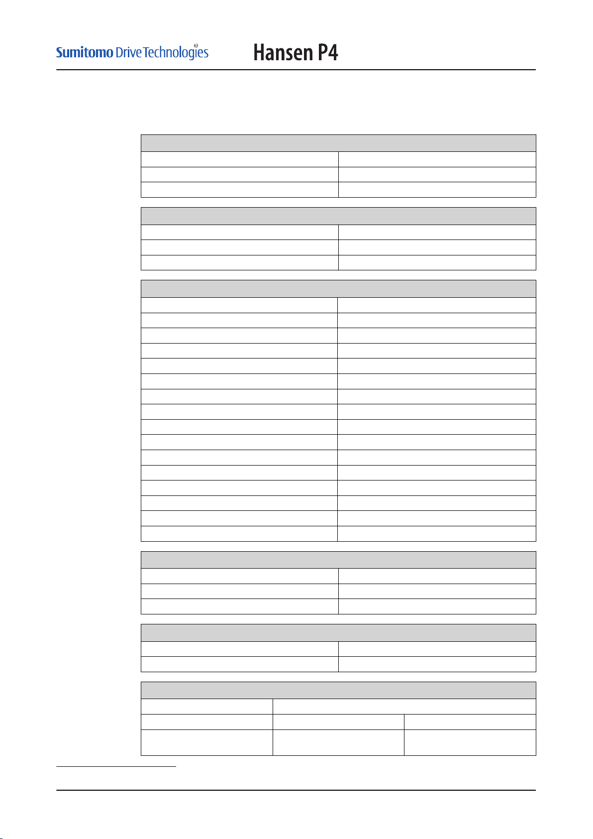
Customer data sheet
Customer References
Name
Project
Application
Hansen Industrial Transmissions References
Manufacturing Number
Order
Gear Unit Type
Technical Specifications
AGMA Power Rating [kW]
AGMA Torque Rating [kNm]
Exact Ratio
Input Speed(s) constant [RPM]
Input Speed(s) variable [RPM]
Output Speed(s) constant [RPM]
Output Speed(s) variable [RPM]
Shaft Arrangement
Motor Power [kW]
Motor Torque [kNm]
Service Factor on Motor Power
Absorbed Power [kW]
Absorbed Torque [kNm]
Service Factor on Absorbed Power
Direction of Rotation (low speed shaft)
Mass of the gear unit1 [kg]
ATEX Specifications
ATEX marking Gear unit
ATEX marking electrical system
Calculated minimum bearing lifetime [Hrs]
Paint
Corrosion category according to ISO12944-2
Colour
Lubrication
Type of gear oil
Oil viscosity grade [ISO VG]
Minimum temperature for the
oil bath for start-up [ºC]
1
Estimated value, without gear oil, without drive package components
IM_405_002_EN
7
Customer data sheet
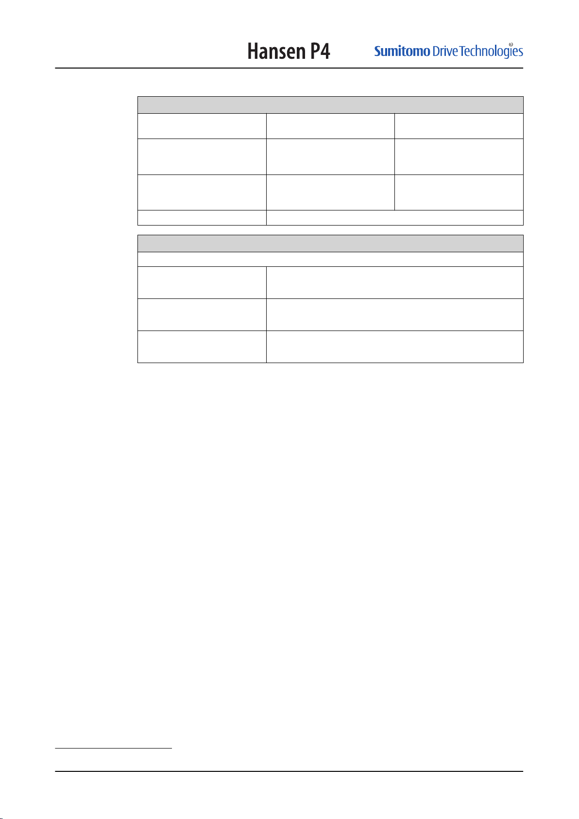
Lubrication
Maximum ambient temperature
[ºC]
Maximum continuous temperature of the gear oil in the oil
bath, during operation [ºC]
Maximum peak temperature of
the gear oil in the oil bath, during operation, [ºC]
Grease type
Storage and protection
The gearbox is adequately treated for storage and corrosion protection up to
1 year indoors
2 years outdoors
2
5 years indoors
2
The applicable value is marked with X
8
IM_405_002_EN
Manual Disclaimer
2
Manual Disclaimer
This Manual and its instructions and information do not purport to cover all details or
variations in the gear unit and do not claim to provide for every possible contingency met
in connection with handling, installation, operation, or maintenance. Hansen Industrial
Transmissions nv does not make any representations, warranties or guarantees, express
or implied, as to the accuracy or completeness of the Manual. Users must be aware that
updates and amendments will be made from time to time to the Manual. It is the user’s
responsibility to determine whether there have been any such updates or amendments.
Neither Hansen Industrial Transmissions nv nor any of its directors, officers, employees
or agents shall be liable in contract, tort or in any other manner whatsoever to any person
for any loss, damage, injury, liability, cost or expense of any nature, including without
limitation incidental, special, direct or consequential damages arising out of or in
connection with the use of the Manual. The user and/or purchaser bears all risks. Should
further information be desired or should particular problems arise which are not covered
sufficiently for the users’ and/or purchaser’s purposes, the matter should be referred to in
writing to Hansen Industrial Transmissions nv.
Warning: Read and understand all instructions and information prior to any
handling including maintenance, installing or starting the gear unit. Failure to
follow instructions could lead to damage, serious injury, or death.
• Only qualified and trained personnel should be involved with the storage (including
transport), commissioning, operation, installation (including removal), inspection,
maintenance and repairs of this gear unit.
• Make sure all your personnel, operators of this gear unit have been professionally and
adequately trained for safe working practices.
• Operators must wear adequate personal protective equipment.
• Ensure all international, EU, national and local safety regulations and codes are
followed when handling, maintaining, installing (including all related actions) the gear
unit.
• Verify the compatibility of the gear unit with the installation it is meant for.
IM_405_002_EN
9
About this document
3
3.1
3.2
3.3
About this document
Function of the document
The document is only applicable for the "Hansen P4" gear unit, from here on in the
document referred to as the gear unit.
The document is for approved installation engineers and gives the information that is
necessary to install and remove the gear unit.
Language
The original instructions of this document are in English. All other language versions are
translations of the original instructions.
If there is any doubt, the English version of the document is binding.
Illustrations
It is not always possible to show the configuration of your gear unit as in the certified
drawing. The illustrations in this document show a typical setup. They are for instruction
or description only.
3.4
3.5
3.6
Use of steps, lists and titles in this document
• The steps in procedures have numbers (123) if the sequence is important.
• The lists and steps with bullets (•) are used if the sequence is not important.
• The lists with letters (abc) are used if the sequence is important.
• In titles of sections, the part between brackets () shows to which type of gear unit or
component of the gear unit the section applies.
How to use this document
Procedure
1. Make sure that you know the structure and the contents of the related documents.
2. Read the safety chapter and make sure that you know all the instructions.
3. Do the steps in the procedures fully and in the correct sequence.
Warnings, cautions and notes used in the document
Type
Warning If you do not obey the instruc-
Description Icon
tion, this can cause injury.
10
Caution If you do not obey the instruc-
tion, this can cause damage to
the gear unit, to equipment or
to property.
IM_405_002_EN
Type Description Icon
Note A note gives more data.
About this document
3.7
Related documents
Document name Document code Target audience
General conditions of sale -
Order acknowledgement OA_
Certified drawing
Installation manual IM_
Maintenance manual MM_
Logbook
Spare parts drawing
Service manual of the lubrication and cooling system
D_
• All personnel
• Approved installation engineers
• Approved installation engineers
• Approved installation engineers
• Approved maintenance engineers
• Approved installation engineers
• Approved maintenance engineers
• Approved maintenance engineers
• Approved installation engineers
• Approved maintenance engineers
IM_405_002_EN
11
About this document
Document name Document code Target audience
Drive package documentation
• Approved installation engineers
• Approved maintenance engineers
3.8
3.9
3.10
Storage of this document and the related documents
This document and the related documents are a part of the gear unit.
• Make sure that you keep the document and the related documents in a dry and clean
location.
• Make sure that the document and the related documents are available to all
personnel.
Abbreviations
Abbreviation
H.I.T. Hansen Industrial Transmissions NV
LSS Low-Speed Shaft
HSS High-Speed Shaft
Description
Customer support
Procedure
1. If more information is necessary, speak to H.I.T.
2. Give the manufacturing number and gear unit type to H.I.T. Refer to the type plate.
12
IM_405_002_EN
Description
4
4.1
4.2
4.2.1
Description
Intended use
The gear unit is a part of a machine.
Only use the gear unit for the application, ambient conditions, operation conditions and
other conditions of use shown in the order acknowledgement.
Resonant vibrations may cause severe overloads on components which may be several
times higher than the nominal load. The responsibility for the vibration analysis which
includes the total system of driver, gearbox, driven equipment, couplings, mounting
conditions and sources of excitation rests with the owner of the installation. H.I.T. is not
responsible for system dynamics and related damage.
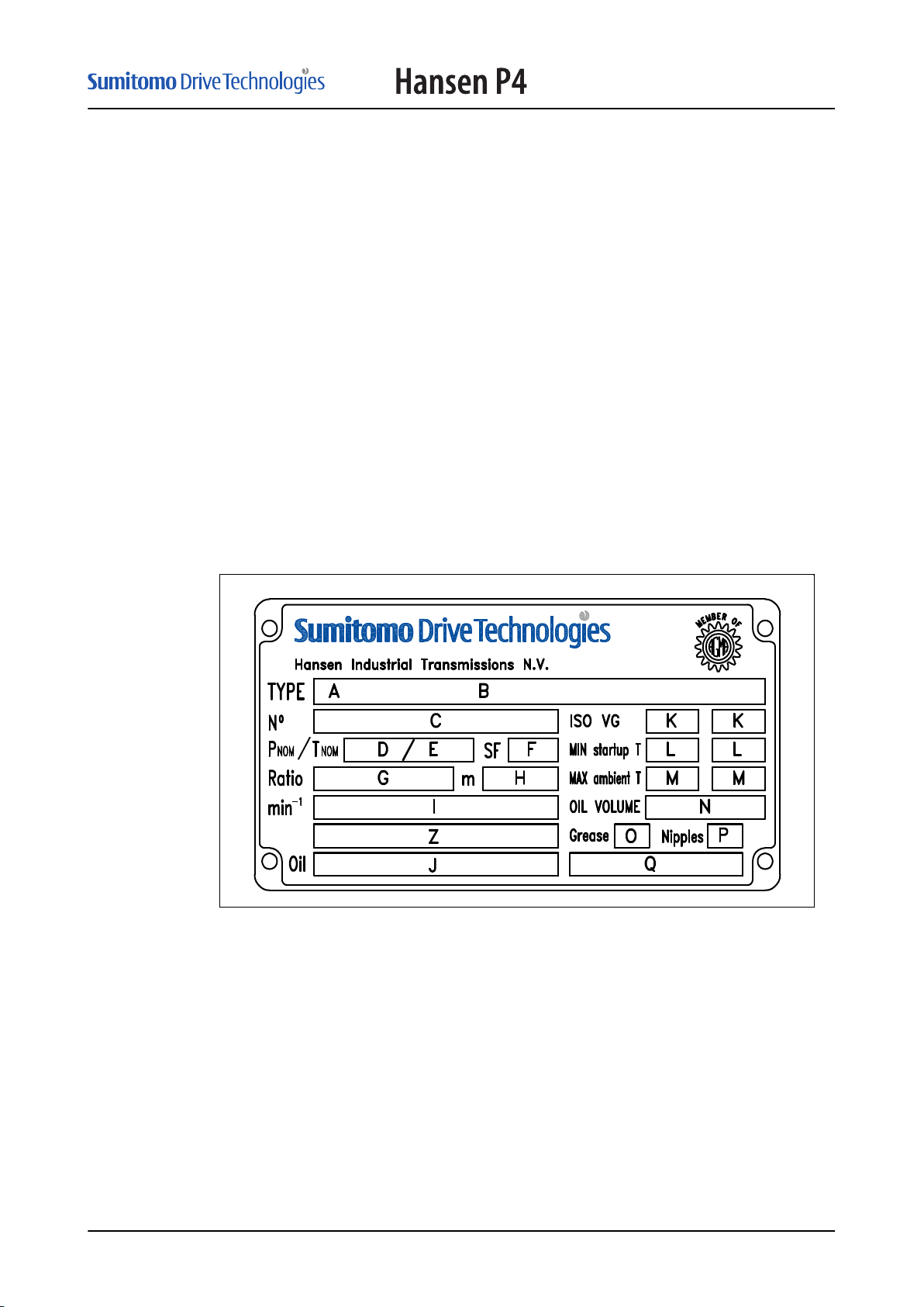
Type plate
Type plate
The type plate gives information about the gear unit.
IM_405_002_EN
A Manufacturing number
B Gear unit type
C Production number
D Nominal power rating at the HSS
E Nominal torque rating at the LSS
F Service factor
G Exact ratio (R: reduction, M: multiplication)
H Mass of the gear unit, without gear oil
I Input speed n1 (output speed n2)
Input speeds n1/n1' (output speeds n2/n2')
13
Description
Variable input speed n1-n1' (variable output speed n2-n2')
J Type of gear oil
K Viscosity of the gear oil
L Minimum temperature for the oil bath for startup
M Maximum ambient temperature for which the viscosity of the gear oil is applicable
N Quantity of gear oil
O Grease quantity type
P Number of lubrication points
Q Grease type
Z Remarks
Note: The certified drawing shows more data:
• illustration of the gear unit type
• connection diagrams
• dimensions
4.3
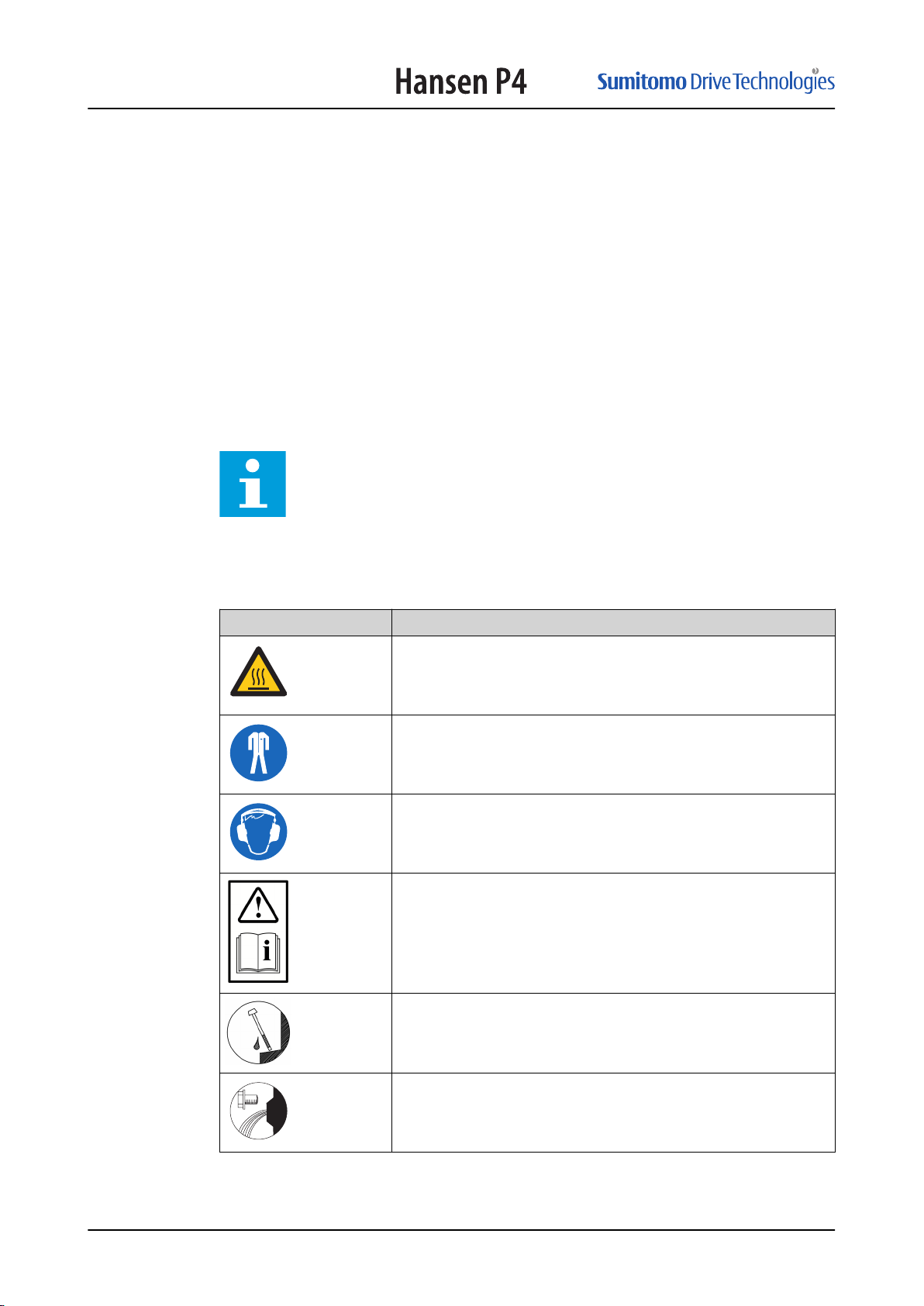
Signs in the documentation and on the gear unit
Sign
Description
Risk of hot surface
Protective clothing is mandatory.
Hearing protection is mandatory.
Read and understand the installation and maintenance manual before
any handling.
Dipstick
14
Oil drain
IM_405_002_EN
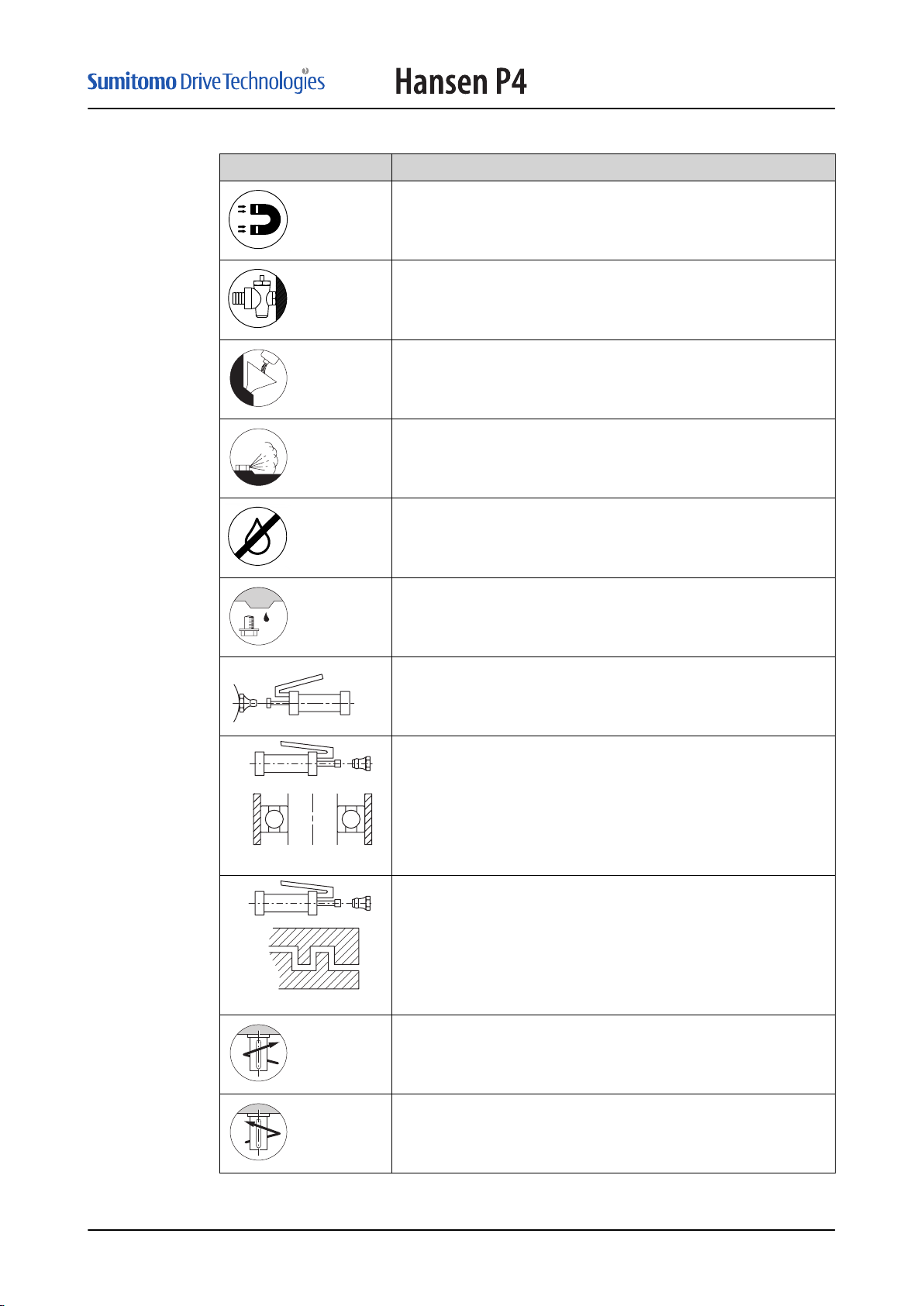
Sign Description
Magnetic
Drain valve with hose coupling
Oil fill plug
Breather plug
Anti-humidity
Description
Condensation drain
Lubrication point for grease
Lubrication point for grease at bearing
Lubrication point for grease at labyrinth seal
Direction of rotation: clockwise
IM_405_002_EN
Direction of rotation: counterclockwise
15
P
C
Description
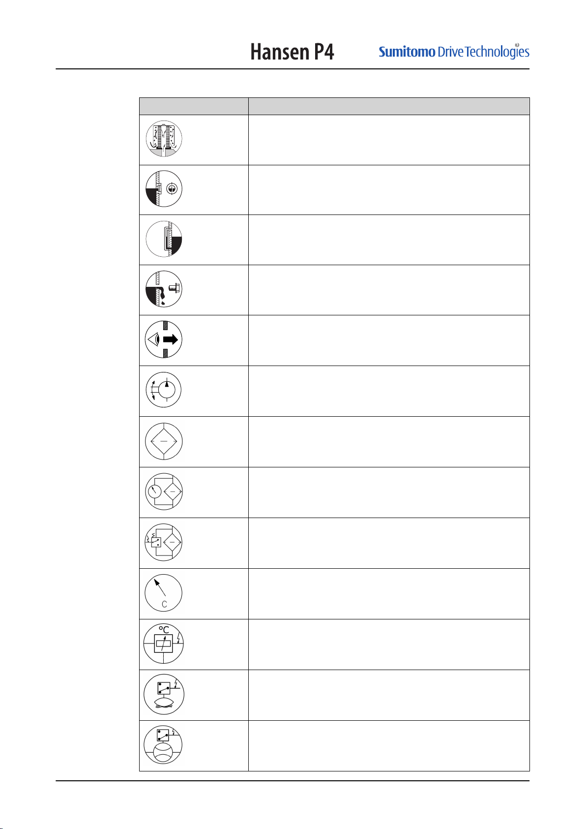
Sign Description
Breather plug to prevent ingress of moisture
Level indicator
Gauge glass
Overflow
Inspection opening
Pump lubrication
Filter
Filter with mechanical contamination indicator
Filter with electrical contamination indicator
Temperature indicator
Temperature transmitter
Level switch
Flow switch
16
IM_405_002_EN
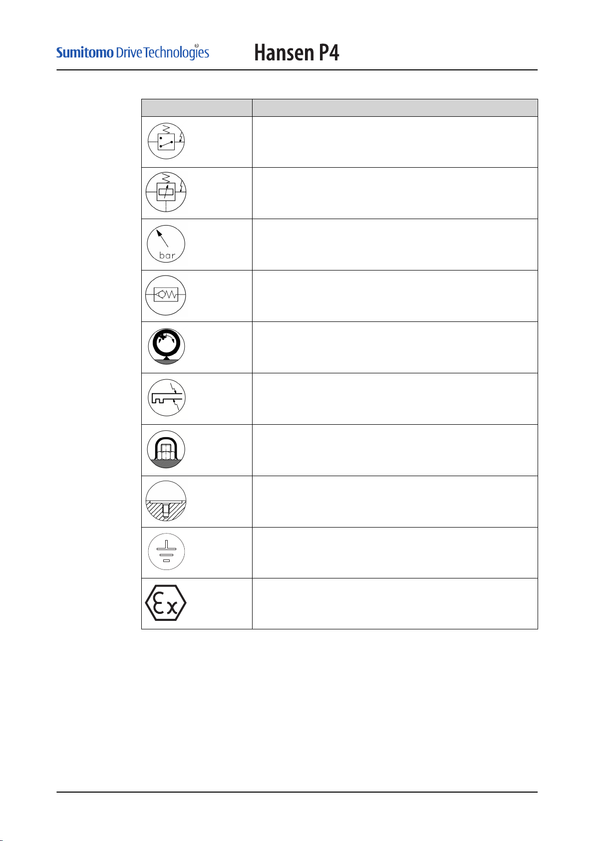
Sign Description
bar
Pressure switch
Pressure transmitter
Pressure indicator
Pressure relief valve
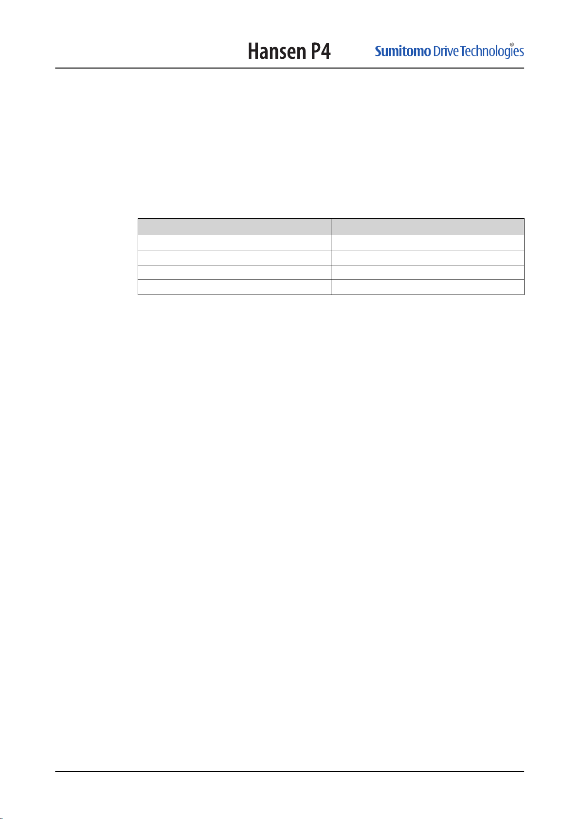
Built-in backstop
Description
4.4
Heater
Protection cap for bolt or nut
Hole for vibration sensor
Ground connection
ATEX
Description of the lubrication of the gear unit
4.4.1
IM_405_002_EN
Function of lubrication
Lubrication is necessary for these functions:
• To prevent metal-to-metal contact in gears and bearings
• To decrease friction losses
• To dissipate generated heat from the gears and the bearings
• To prevent corrosion
17
Description
These parameters have an effect on the type of lubrication system for the gear unit:
• Gear speed
• Mounting position of the gear unit
• Operation conditions
The certified drawing shows the lubrication system that is used for your gear unit.
4.4.2
4.4.3
Splash lubrication
Splash lubrication is the standard for gear units with horizontal LSS of these types:
Number of stages Speed at the HSS [min-1]
1 750 to 1800
2 750 to 1800
3 750 to 1800
4 1000 to 1800
In other conditions, the lubrication system can be different. The type plate shows the
approved speed of the HSS.
Force-feed lubrication
An oil pump lubricates all turning parts above the level of the oil bath. The oil pump
pumps the oil through pressure lines.
There are different types of oil pumps:
• Integrated pump: one of the shafts of the gear unit operates the oil pump.
• Motor pump: a motor operates the oil pump.
The lubrication can be circulation lubrication or pressure lubrication.
Integrated pump
4.5
4.6
Refer to the certified drawing for the lubrication system for your gear unit. The lubrication
system can have these parts:
• A pump
• A filter with bypass
• A flow switch
The pump can operate in two directions of rotation.
Motor pump
A sign on the pump shows the direction of rotation of the motor shaft of the motor pump.
Breather plug
A breather plug is installed to prevent a too high pressure in the gear unit.
Cooling system
A cooling system can be necessary to remove heat from the gear unit. Friction and
churning of gears and bearings in the gear oil causes the heat.
The certified drawing shows the cooling system that is used for your gear unit, if any.
18
IM_405_002_EN

Description
4.7
Direction of rotation of the shafts
As a standard, the shafts of the gear unit can turn in two directions. If the shafts of the
gear unit can only turn in one direction, a sign on the gear unit and the certified drawing
shows this.
IM_405_002_EN
19
Safety
5
5.1
Safety
Restrictions
Warning: Use of the gear unit in ways other than described in the related
documents may result in injury, death, or property and equipment damage.
Use the gear unit only as described in the related documents.
H.I.T. cannot be held responsible for injuries or damages resulting from non-standard,
unintended use of the gear unit. The gear unit is designed and intended only for the
purpose described in the related documents.
Unintended use includes these actions:
• Making changes to the gear unit that have not been recommended in the related
documents or using parts that are not replacement parts or accessories from H.I.T.
• Use of materials or equipment that are inappropriate or incompatible with the gear
unit.
• Use of gear oils and grease that is not indicated on the type plate or the specifications
in this document.
• Allowing unapproved personnel to perform any task on or with the gear unit.
5.2
5.3
Approved installation engineer
The term approved installation engineer is specified here as a person that fully knows the
gear unit and its safe operation. Approved installation engineers obey all related safety
regulations and are approved to safely install the gear unit.
It is the responsibility of the company that owns the system where the gear unit is part of
to make sure that all installation engineers obey these requirements.
General safety instructions
Warning: Obey the specifications that the certified drawing shows. If
specifications in this document and the certified drawing for the same item are
different, only the specifications in the certified drawing are applicable.
• When you do work on or with the gear unit, obey all legislation and regulations that
apply to safety and work requirements, that apply in the country and at the location
where you do work on the gear unit.
• Obey the safety instructions of the manufacturer of all chemical materials, including
gear oil and grease. Refer to the material data sheets of the chemical material. Make
sure that all personnel that installs, does maintenance and servicing on the gear unit,
receives these safety instructions.
• Do not open the gear unit near an open flame, spark or hot object. If not this can
cause ignition of the fumes of the oil.
• If the gear unit is used as a part of a system that moves persons, obey all regulations
and install all necessary safety devices.
20
IM_405_002_EN
Safety
5.4
5.5
5.6
Safety instructions for installation
• Make sure that the personnel that lift the gear unit are approved and obey state-of-theart safety procedures and state-of-the-art lifting equipment.
• Obey the European Directives 2006/42/EG and the local safety regulations and install
guards and other safety equipment.
• Make sure that the drive group the gear unit is a part of, cannot start when you install
the gear unit.
• If safety devices are removed for installation, make sure they are correctly installed
again before you start the gear unit.
• Make sure that the installation agrees with the EMC directive.
Special safety instructions (backstop)
Warning:
• Do not loosen a part of the backstop when there is load on the gear unit. In
this condition, the gear unit can turn in the incorrect direction.
• Make sure that a failure of a backstop cannot cause injury or damage to
the system.
Noise and vibrations
5.7
5.8
The drive group, which the gear unit is a part of, and the attached parts cause vibrations
and noise.
To agree with local legislation, it can be necessary to decrease the noise of the drive
group and the attached parts. Speak to H.I.T.
If you cannot do such procedures, all personnel that does work with or adjacent to the
drive group must wear correct personnel protection equipment, to decrease the noise to
the ears.
Make sure that the vibration agrees with ISO standard 10816-3.
Partly completed machine
The gear unit is a partly completed machine. It is a part of a drive group. Refer to the
documentation of the drive group and obey all instructions of the drive group.
Instructions in case of a fire
Warning: After a fire, protective clothing and respiratory equipment are
mandatory to handle the gear unit. After a fire, the gear unit can contain
dangerous substances that cause injury when you touch or breath them.
• Do not start a gear unit that has burn marks. Speak to H.I.T.
• Hazardous substances of combustion can be generated in a fire involving materials in
section
Materials of the gear unit
on page 52.
IM_405_002_EN
21

Safety
5.9
Warranty
The warranty clause of the general conditions of sale applies to gear units installed and
maintained as per instructions contained in this document, including the related
documents, and in any additional instruction leaflets supplied with the gear unit insofar as
the gear unit operates within the service and rating conditions put forward in the order
acknowledgment and on the certified drawing.
Non compliance with these instructions, injudicious choice of lubricant or a lack of
maintenance will render warranty agreement invalid.
This warranty clause applies to all parts of the gear unit with the exception of those parts
which are subject to wear.
22
IM_405_002_EN
 Loading...