

Page 1
Page 2

INDEX
1. Introduction
2. Specifications
3. Dimension
4. Installation
5. Electrical Wiring
6. Initial Startup of the unit
7. Operation
8. Maintenance
9. Troubleshooting
POO L H EA T P U MP
10. Explode diagram
Page 3

1.Introduction
POO L H EA T P U MP
Thank y ou for using swimm ing pool hea t pump for you r pool heati ng, it will he at your
pool wa ter and keep t he constan t temperat ure when amb ient te mpe ratur e at +7℃ t o 40℃
In orde r to offer qualif ied, relia ble and flex ible he at pu mp unit t o our c ustom er, pl ease re ad
this ma nual caref ully befor e installi ng, operat ing and t rou blesh oot ing, th en pr ocess a cco rding ly.
This ma nual inclu des all nece ssary info rmation
ATTENTION
!
● The hea t pump unit mu st be instal led by quali fied techn ician s fro m after -sa les
HANSC RAFT
cente r or authori zed distri butor.
● Opera ting and mai ntaining a ccording t o recom men ded tim e and f reque ncy o n
the man ual.
● Use onl y standard s pare parts .
01
Page 4
2. Specifications
2.1 Design, R410A ,HEATI NG ONLYHorizon tal
POO L H EA T P U MP
Horizontal design, ABS C abine t
Model
* Heating Capacity at Air 27℃, Wat er 27 , Humidity 80%℃
Heat Output (kW)
Power Consumption (kW)
COP
* Heating Capacity at Air 15℃, Wat er 26 , Humidity 70%℃
Heat Output (kW)
Power Consumption (kW)
COP
* General data
Voltage
Rated Current (A)
Fuse Current
Advised pool volume
(with pool cover)
Advised water flux
Wat er Pres sure Dr op
Condenser
Compressor type
Wat er pipe i n-out
Fan Speed
Noise level(10m)
Noise level(1m)
Refrigerant
* Dimension/ Weight
Net Wei ght
Gross Weight
Net Dimension
Packing Dimension
Above d ata i s sub ject to modi fic ati on without n oti ce,
Evolu tio n 25 Evolu tio n 40 Evolu tio n 60
6.8 10
1.09 1.60 2.07
6.25 6.25 6.25
4.3 6 .5 8.2
1.02 1.48 1.86
4.2 4 .4 4.4
220-240V/50Hz/1PH
4.7 7 .0 9.0
10A 15A 20A
15-25m³ 25-35m³ 30-60m³
2.5~3.7m /h³ 2.8~5.6m /h³ 3.5~7.1m /h³
12KPa 12KPa 15KPa
Tit anium i n PVC
Rotary/R410a
830~870RPM
40dB(A)
46dB(A)
800g 1100g 1200g
32kg
37kg
1030*335*560mm
1080*360*610mm
13
50mm
40dB(A)
47dB(A)
37kg
42kg
pleas e tak e the n ameplate a s sta nda rd.
43dB(A)
48dB(A)
61kg
68kg
1025*350*620mm
1120*3 80*66 5mm
02
Page 5
3. Dimension
POO L H EA T P U MP
4. Installation
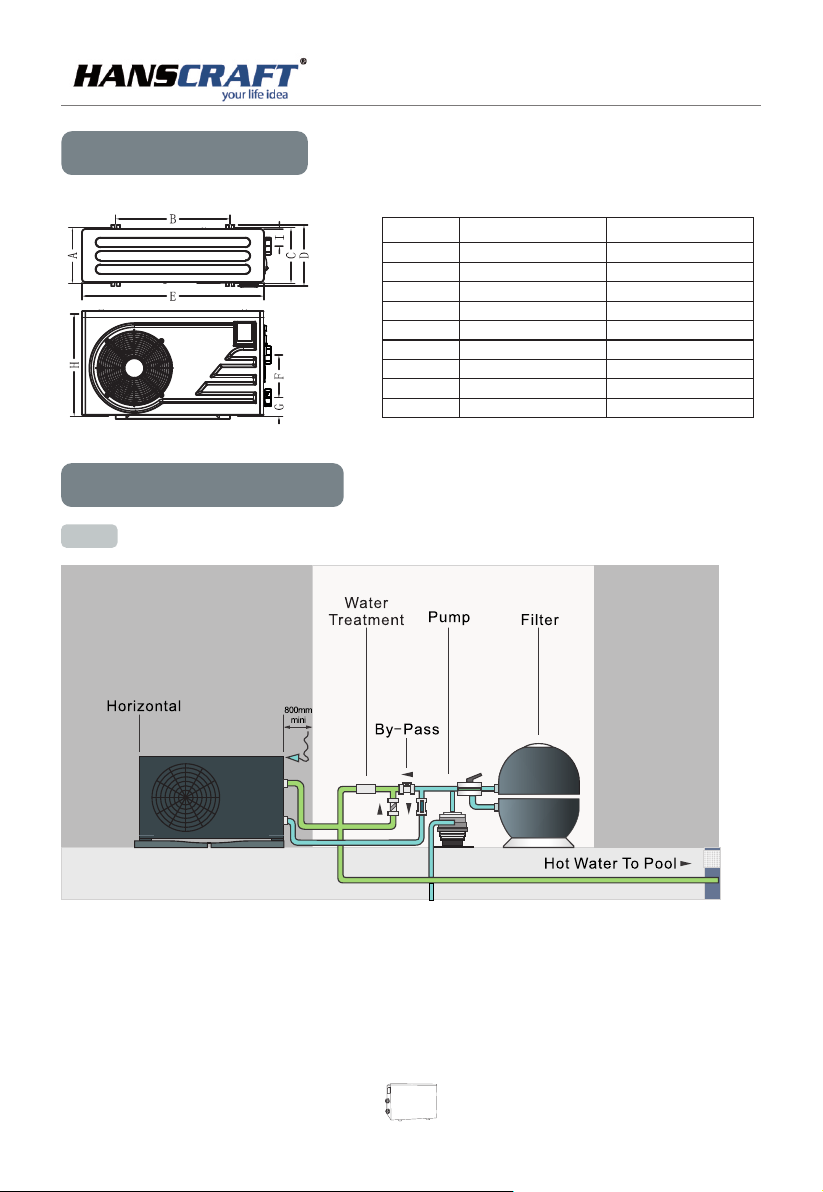
4.1 Ins tallation illustration
Models
A
B
C
D
E
F
G
H
I
EVOLUTION 25
EVOLUTION 40
302
622
288
332
988
230
103
557
98
Unit : mm
EVOLUTION 60
326
655
306
350
1026
340
108
620
92
NOTE: Th e factory only provides t he he at pu mp un it. The ot her i tem s in th e ill ust rat ion a re ne ces sary
spare part s for t he wa ter s yst em wh ich a re pr ovi ded b y users or installers.
03
Page 6
POO L H EA T P U MP
ATTE NTI ON:
!
Please f oll ow these st eps w hen opera tin g the first t ime :
1.Op en va lve a nd charge w ate r
2.Ma ke su re th at the pump a nd th e water-i n pip e have been f ill ed wi th wat er
3.Close t he va lve and sta rt th e unit
4.2 Ins tallation
(1) The he at pu mp unit mus t be in stalled b y pro fession al te chn icia ns .o the rwis e uni t may b e dama ged o r bod y inju red ,
even dea d
(2) The un it is d esigned f or ou tdoor loc ati on with goo d ven til atio n. Re cir cula tio n of co ld dis cha rge a ir bac k int o
eva por ato r coil will g rea tly reduc e hea tin g capa cit y and e ffic ien cy of th e uni t, wh ich wi ll vo id th e comp res sor
warran ty.
(3) The un it ca n be instal led a lmost any whe re in the out doo rs. To get a go od pe rfor man ce ,i t needs to me et th e three
fac tor s :
a) Go od ve nti lation
b) St abl e and r eliable p owe r supply
c) Re cyc led w ater syst em
The d iff erence fr om ga s water hea ter, i t should no t bri ng en viro nme nta l poll uti on or h ave th e ins tal ling p rob lem s
in-win dy ar eas.
(4) The un it sh ould not be i nst alled in a li mit ed ai r vent ila tio n area , or pl ace d in a bus h whe re it w ill bl ock t he ai r inle t .
The se lo cat ion deny th e uni t of a contin uou s source of f res h air . When s eas ons c hang ing , it ma y stic k lea ves o n
the e vap ora tor coil ,t her eby reduc ing i ts eff ici enc y and im pac t of it s serv ice l ife .
(5) For in doo r install ati on, pleas e con sul t more i nst ruc tion f rom t ech nici ans .
(6) When i nst all a bypas s, it s hould be no t exc eed 30% of no min al fl ow rat e
(7 Must ma ke Wat er le vel highe r tha n the circu lat ion pump lo cat ion .
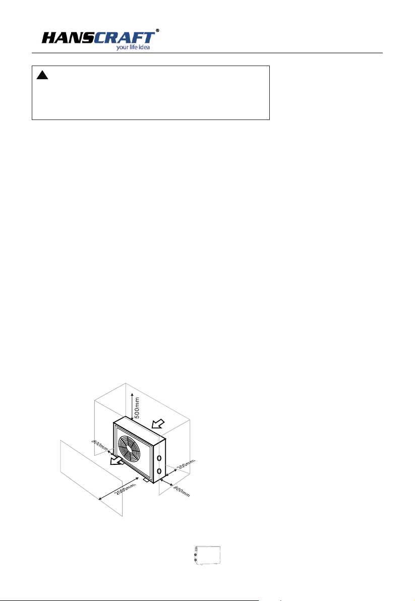
(8) Belo w pic ture show t he mi nimum req uir ed di stan ce on e ach s ide of p ool h eat p ump un it.
Air i nlet
Air o utlet
04
Page 7
POO L H EA T P U MP
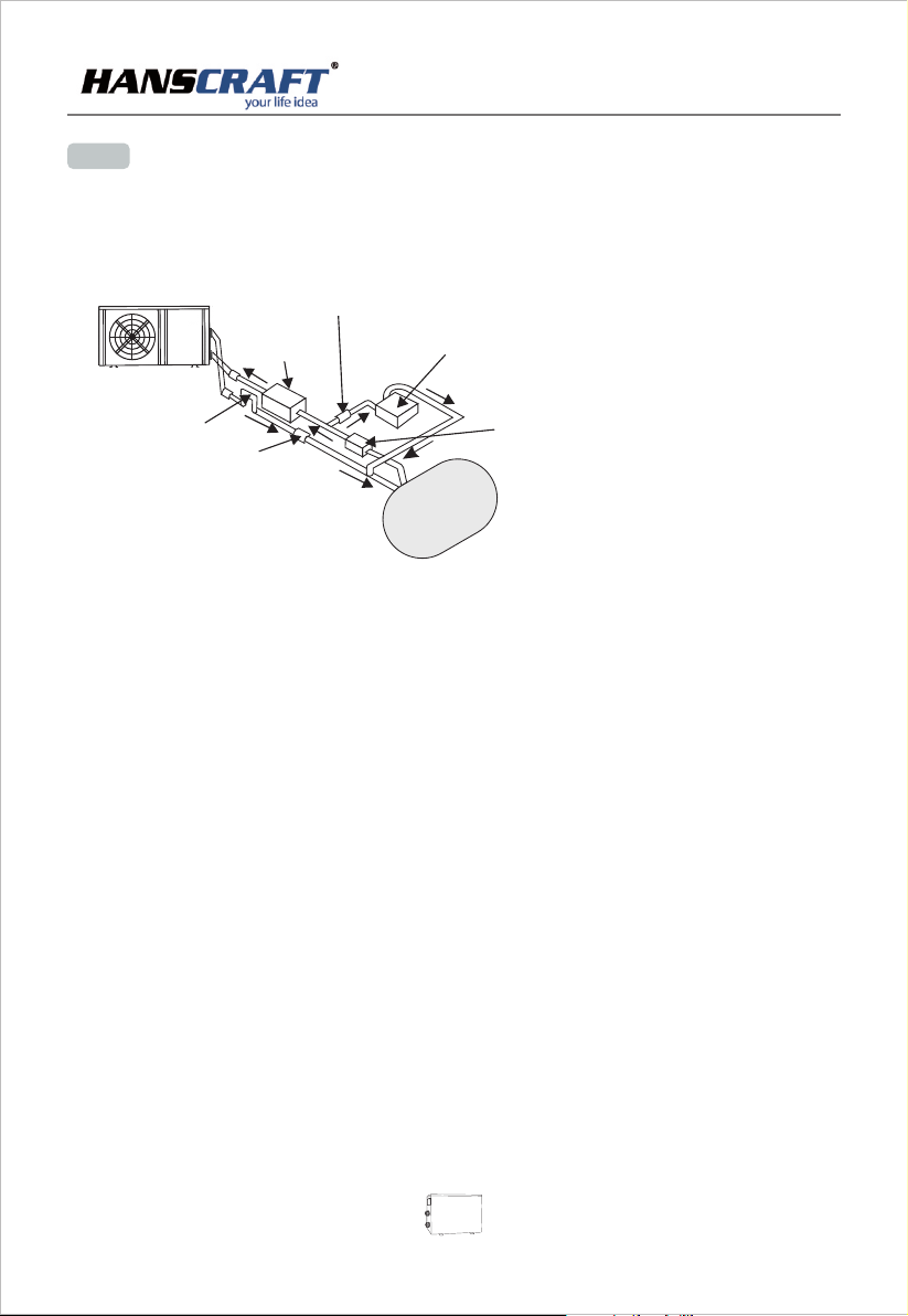
4.3 's inst ruc tio n to yo ur system is also c rit ica l to th e heater's l ife .The loc ation o f chemical
If an aut oma tic c hlo rinator or brom ina tes i s use d, it must be locat ed do wns tre am of the heat er.
A trap mus t be in sta lle d between the chl ori nat or an d the heater t o pre ven t chl orine return in to th e
heat pu mp. ( See b elo w pictures)
Pressu re- typ e Chl ori nato r or Br omi nato r
Che ck- va lve
Fil ter
P- tra p
Che ck- va lve
(1) Typic all y, the po ol he at pump uni t sho uld b e inst all ed as ide th e poo ls, l ess th an 7. 5 met ers di sta nce . If it is
instal led f arther aw ay, the pipe lin e system wi ll ca use g reat er he at lo ss. Th e mos t of pip eli ne ar e inst all ed un der
ground , alt hough the p ipe line syst em ha s to do t herm al in sul atio n ,bu t tun nels a nd th e soi l arou nd wi ll st ill oc cur
heat exc han ge ,for exa mpl e,e ach 3 0 met ers ( 15 m ete rs to a nd fro m the p ump =30 me ter s tot al),un les s the gr oun d
is wet or th e wat er table is h igh .A ver y rou gh es tima te of h eat l oss pe r 30 me ter s is 0.6 KW pe r hou r (2000BT U) fo r
every 5℃ su rro unding th e pip e,w hic h tra nsla tes t o abo ut 3% to 5 % inc rea se in run tim e.
(2) To ge t the be st he at ex chan ge of h eat p ump unit, i t sho uld be matc hed t he normal r ate o f wat er flo w
recomm end ed in speci fic ation she et.
(3) It is re qui red to incr eas e the disch arg e pip e to pre ven t fre ezin g in co ld se ason , to pu t “T” f itti ng an d bal l valv e to
facili tat e changin g the w ater in win ter o r emp tyin g the w ate r out of s yst em to p reve nt fr eez ing wh en HP s top
operat ing a t the ambie nt te mperatu re be low z ero ,o the rwi se the u nit m ay be d amag ed .
(4) It is su gge sted to ins tal l the quick a dap tor in fron t of wa ter i n-ou t con nec tion , whi ch co uld di sch arg e wate r eas ily
to preve nt wa ter freez ing , and be conv eni ent f or mai nte nan ce and s erv ice .
(5) When u nit r unning ,t her e will be som e con den sati on wa ter d isch arg ed fr om the b ott om ,p leas e hol d the
draina ge no zzle (acc ess ory ) into th e hol e and c lip we ll ,a nd th en con nec t a pip e to dra in th e con dens ati on wa ter ou t.
(6) If wat er pr essure is o ver 1 0 KPA ,or wa ter f low rate is m ore t han 11 cu bic m ete rs thr oug h hea t exch ang er ,i t is
necess ary t o install t he by -pass pip e in wa ter s yste m.
Chlor ina tor
Wat er pum p
05
Page 8
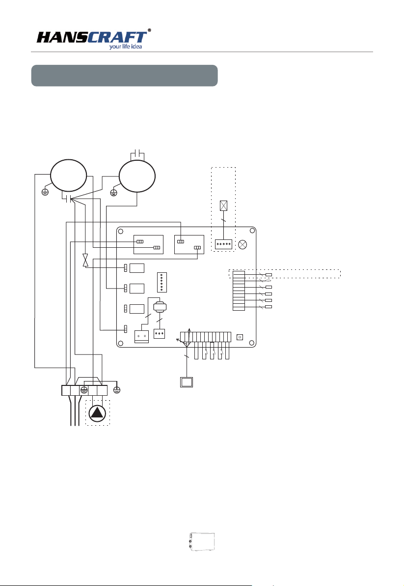
5. Electrical Wiring
wimming pool heat pump wiring diagramS
Evolution 25 / Evolution 40
FA N CAP ACI TO R
RE D
OR G
R WH T
COMPRESSOR
S BL K
YL W/G RN
CO MPR ESS OR
CA PAC ITO R
BL U
L
N
WH T
C RE D
BL U
4- WA Y VA LV E
BL U
BL U
BL U
BL K
OUTDOOR MOTOR
YL W/G RN
BL K
BR N
RE D
3
OU T3
OU T4
OU T5
AC -N
CN 1
OU T1
2
YL W/G RN
1
2
BR N
4
RE D
PC B o ar d
Pr og ra mm in g
Tra n sfo r mer
2
BL U
CN 2
BR N
Rem o te co n tro lle r
POO L H EA T P U MP
5
OU T2
3
YL W
12 V
EN T
3
Ele c tro n ic Ex pan s ion V a lve
LE D
4
CN 3
FS
GN D
GN D
KY IN
Rem o te sw i tch
Wat e r f w swi t ch
RU N/ POW
2
GN D
T6
GN D
T5
GN D
T4
GN D
T3
GN D
T2
GN D
T1
CN 4
PP
HP
LP
GN D
GN D
GN D
GN D
SW 1
Hig h v olt a ge sw itc h
Pha s e seq u enc e pro t ect i on
Low v o lta g e swi tch
Coo l ing c o il te mpe r atu r e sen s or
2
Amb i ent emp e rat u re t sen s or
2
Ref r ige r ant r etu r n tem p era t ure s ens o r
2
H coi l t emp e rat ure s e nso reat i ng
2
Wat e r out l et co il te m per a tur e s ens or
2
Wat e r inl e t coi l tem p era t ure s e nso r
lo
POWER 220-240V/50Hz
SINGLE-WATER PUMP
* The dotted line part are only used in some models
06
Page 9
POO L H EA T P U MP
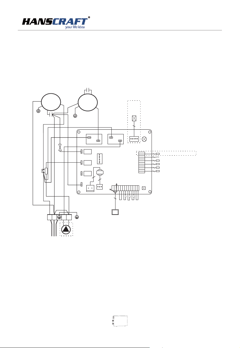
Swimming pool heat pump wiring diagram
Evolution 60
FA N CAP ACI TOR
RE D
OR G
R WH T
YL W/ GR N
CO MPR ESS OR
CA PAC ITO R
AC CONT A C T OR
BR N
C OM P
S BL K
C RE D
BL U
BL U
4- WA Y VA LV E
BL U
L
N
OU T DO OR M OT OR
T
H
W
OU T3
OU T4
OU T5
BL K
5
OU T1
3
4
PC Bo a r d
Pr og ra mm ing
OU T2
3
Tra nsf o rm e r
2
2
YL W
BL U
12V
CN 2
CN 1
BR N
Rem ote c ont rol ler
Ele ctr oni c Exp ans ion V alv e
LE D
4
ENT
GND
KYI N
3
Rem ote s wit ch
RU N/P OW
2
GND
T6
GND
T5
GND
T4
GND
T3
GND
T2
GND
T1
CN 4
CN 3
PP
HP
LP
FS
GND
GND
GND
GND
GND
Wat er f w s wit ch
SW 1
Hig h vol tag e swi tch
Pha se se que nce p rot ect io n
Low v olt age s wit ch
Coo lin g coi l tem per atu re s e ns o r
2
Amb ien t em pe r at u re t se n so r
2
Ref rig era nt re tur n tem pe r at u re s e ns o r
2
H co il t e mp era tur e sen soreat ing
2
Wat er ou tle t coi l tem per at u re s e ns o r
2
Wat er in let c oil t emp era tu r e se n so r
YL W/ GR N
BR N
BR N
BL U
RE D
RE D
AC -N
BL U
BL U
lo
YL W/ GR N
1
2
POWER 208-230V/60Hz
SINGLE-WATER PUMP
* The dotted line part are only used in some models
07
Page 10
POO L H EA T P U MP
6. Initial Startup of the unit
Note: Plea se ma ke sure the w ate r pump is run nin g in ci rcul ati on wi th ade qua te ra te of wa ter f low.
Startup Procedure afte r Ins tallati on is c omplete d, an d ple ase fo llo w the se ste ps:
(1)Turn on you r fil ter pump ,c hec k water lea ks an d verify fl ow of s wim ming p ool
(2)Turn on the e lec trical po wer s upply to th e uni t, then pre ss th e key O N/OF F of wi re co ntro lle r, it sh ould s tar t in se vera l
sec ond s.
(3)Aft er ru nning a few m inu tes make su re th e air venti lat ion f rom th e sid e (to p) of th e uni t is co oler ( B etw een 5℃ a nd 10 ℃)
(4)Whe n tur n off th e fil ter pump , th e uni t should al so tu rn off a uto mat ical ly , if n ot, t hen ad jus t the f low sw itc h
(5)All ow th e unit and po ol pu mp to run 24 ho urs p er da y unti l the w ate r reac hes t he de sire d tem per atur e .Wh en th e
tem per atu re reache s the s etting va lue , the HP unit w ill s hut do wn ,w hen t he poo l tem per atur e dro ps mo re tha n 1℃,pl eas e
restar t (as l ong as HP uni t is runnin g )
Wat er Flow S witch :
It is e qui ppe d with a flow s wit ch for prot ect ing the HP un it ru nnin g wit h ade quat e wat er fl ow rat e .It w ill t urn on w hen t he
pool pum p run s and shut it o ff when the p ump s huts off. I f the pool wa ter l eve l high er th an 1 m ab ove or b elo w the h eat
pump's a uto matic adj ust ment knob , you r dealer ma y nee d to ad just i ts in iti al sta rtu p.
Time De lay:
HP un it sh ould be equ ipp ed with a 3-m inu te bu ilt- in so lid -sta te re -st art de lay p rot ecti on. Ti me de lay co ntr ol is a n inte gra l
part of th e cir cuit cont rol , it can elim ina te restar t cyc lin g and co nta cto r chat ter.
The time d ela y will auto mat ically re sta rt the HP uni t app roxi mat ely 3 m inut es af ter e ach co ntr ol ci rcui t int err upti on .E ven a
brief po wer i nterrup tio n will acti vat e the solid s tat e 3 min ute re sta rt de lay an d pre ven t the un it fr om th e star tin g unt il the 3
minute s cou ntdown is c omp leted.
7. Operation Heating Only
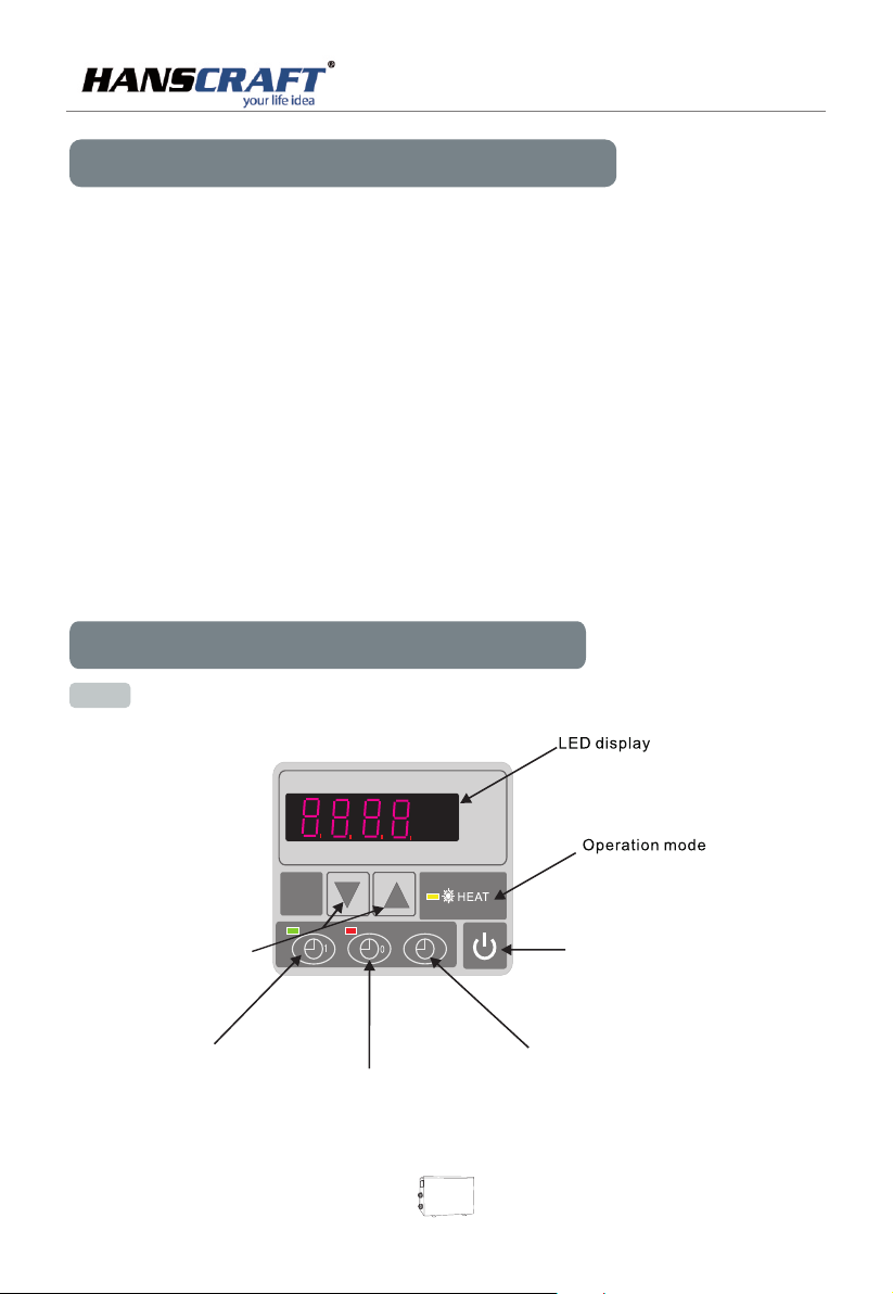
7.1 The f unctions of LE D wire controller
Up and down button
Tim er on b utton
Tim er off button
08
Tim e
display
ON/O FF
button
Page 11
POO L H EA T P U MP
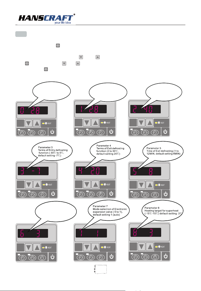
7. 2 How to set o peration pa rameter
(LED di spl ay wi l sho w real time if HP unit is switc hed o ff. )
(1) Pre ss an d hol d in fo r 5 sec onds to ente r ope rat ing p arameter sett ing i nte rfa ce.
(2) Und er pa ram ete r setting, pres s and t o cho ose p arameter belo w fro m “0” t o “A” , press
again then p res s or to s tar t setting param ete rs( see o peration p ara met er ta ble)
and pre ss to c onf irm ; Lea ve it 8 second s,, LED w ill d isplay water in t emp era tur e(under
runni ng) o r cur ren t time(until st ops ).
Par amete r 0
To set th e enter ing wat er temp .
und er cool ing mod e (15-3 5℃,
def ault se tting :28℃)
Par amete r 6
Mod e:0 He at,1 H eat and C ool
Def ault se tting :0
Par amete r 1
To set th e enter ing wat er
tem p. unde r heati ng mode
(15 -40℃, def ault
set ting: 28℃)
Par amete r 2
Total w orkin g time of
com press or afte r frost ing
(30 -90MI N ,defa ult
set ting : 40 MIN)
09
Page 12
POO L H EA T P U MP
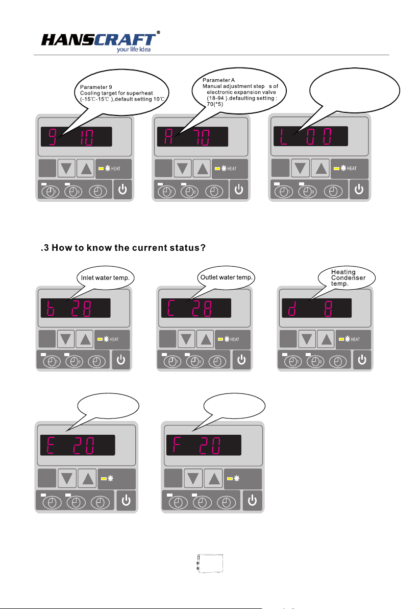
Par amete r L
Mod e:inl et wate r
tem perat ure cor recti on
Def ault se tting 0 0
7
1
Gas retu rn te mp.
HEAT
0
1
Ambien t tem p.
HEAT
0
10
Page 13
POO L H EA T P U MP
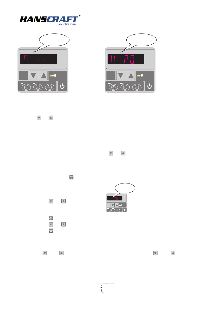
Cooling Condenser
temp.
Act ual ste ps of
ele ctron ic
exp ansio n valve
HEAT
1
0
1
0
(1) Pre ss or t o che ck wa ter -in/water -ou t/h eat ing condenser
/back g as/ amb ien t temperature .
(2) Whe n the u nit i s swi tched off, current time i s dis pla yed .
7. 4 Water tempe rature settin g:
A. Under running status,
(1) Und er cu rre nt he ating mode, onl y pre ss or t o adj ust heating wat er te mpe rat ure.
B. Under standby status,
(1) Pre ss an d hol d in fo r 5 sec onds until p ara met ers f lash to enter ope rat ing s ett ing
Parame ter 1
To set the ent ering w ater
temp. un der hea ting mo de
(15-35℃, d efaul t
(2) Pre ss or t o rea ch Pa ram eter 1 ,
settin g:28℃)
HEAT
MODE
101
0
HEAT
(3) Pre ss ag ain .
(4) Pre ss or t o set t emp era ture.
(5) Pre ss to c onf irm a nd wa it for 8 secon ds. M ach ine w ill reset new tem per atu re.
7
.5 Locking s etting
Long press and to loc k the par amete rs, Pre ss and fo r
seconds
again to unlock
5 seconds 5
11
Page 14

POO L H EA T P U MP
7.7. Time sett ing:
6
Press to set the time, and press and to a djust t he time
press the again to store the new data.
Timer on se tting
7
Press to set the time for HP start t o run ,an d press o r to adju st .
Press the
1
1
again to store the new data.
the time
7.8 Timer o ff setting
Press to set the time for HP stop ru nning , press o r to adju st .
then, press again to store the new data.
0
0
the off t ime
7. 9 Cancel Timer Func tion
Press or first, then press to cancel timer on or timer off setti ng.
0
1
7. 10 Syste m reset funct ion
Press and at the same time for 10s, parameter from “0” to “L” to be reset to defa ult.
12
Page 15
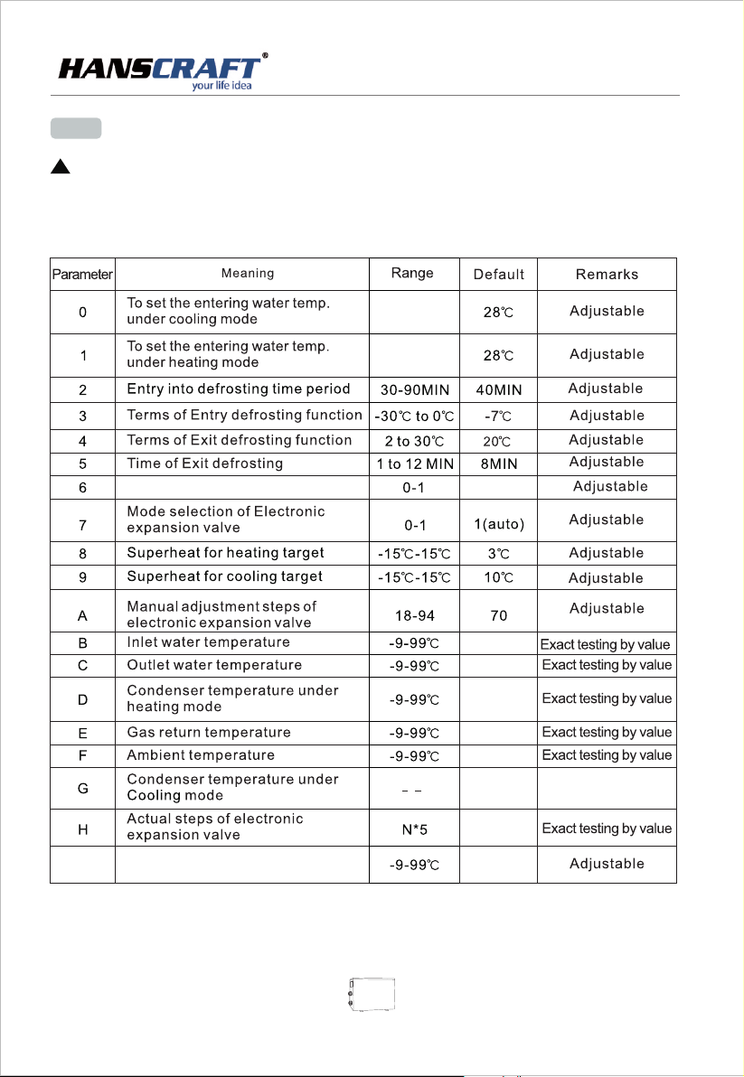
7.4 RUNNING DATA SE TTING
ATTENT ION:
!
HP runni ng pa rameter s mus t be checke d aft er instal lat ion a nd bef ore f irs t used .
Whe n the L ED on , it will dis pla ys water in let t emp erat ure .
Whe n the L ED off, it wi ll di splays " OFF ".
Whe n the L ED on , the water t emp c ould be cha nge d.
15-35℃
15-40℃
POO L H EA T P U MP
Mode:0 heat ,1 hea t and coo l
0 ( Heat)
/
Inlet water temperature
L
correction
Remarks :
(1) LED wi re co ntrolle r can o perate th e wat er pump aft er co nne cted a ddi tio nal ca ble t o the p ump de vic e in th e posi tio n
of “W ATER PU MP” t erminal a ccu rately .
(2) It is ne ces sary to put a n ext ra 3-phas e tra nsfer dev ice f or 3 phase wa ter p ump .
13
Page 16

POO L H EA T P U MP
8. Maintenance
(1) You should check the water supply system regularly as to avoid the air entering the system
and occurrence of low water flow, because it would reduce the performance and reliability
of pool heat pump unit.
(2) Clean your spas and filtration system regularly to avoid the damage of the unit as a
result of the dirty of clogged filter.
(3) Keep the HP unit dry, clean, well-ventilated and always clean air side of the heat exchanger,
which can maintain a good heat exchanger and energy saving.
(4) Only a qualified service technician is allowed to operate pressure of the refrigeration system.
(5) Check power cable connection, if heat pump starts to operate abnormally, you should turn
it off and contact with qualified technicians.
(6) You should the water from water pump and other water system, to prevent from the
freezing damage in winter seasons.
The heat pump and all associated pipe work must be drained down during winter or freezing
(7)
conditions.
Always flush with clean water and check thoroughly before recommissioning
(8)
the heat pump
.
drain
9. Troubleshooting guide
WARNING
Incorrect installation could result in personal i njury.
(1) .
Do not adjust internal control
(2) If y ou are no t famil iar wit h your wa ter fil trati on syst em and he ater
(a) Do n ot try to a djust , consu lt the pr ofess ional d ealer.
(b) Be fore us e, plea se read t he Inst allat ion and U ser's G uide.
Note: power supply before
TURN OFF any maintenance work
14
Page 17
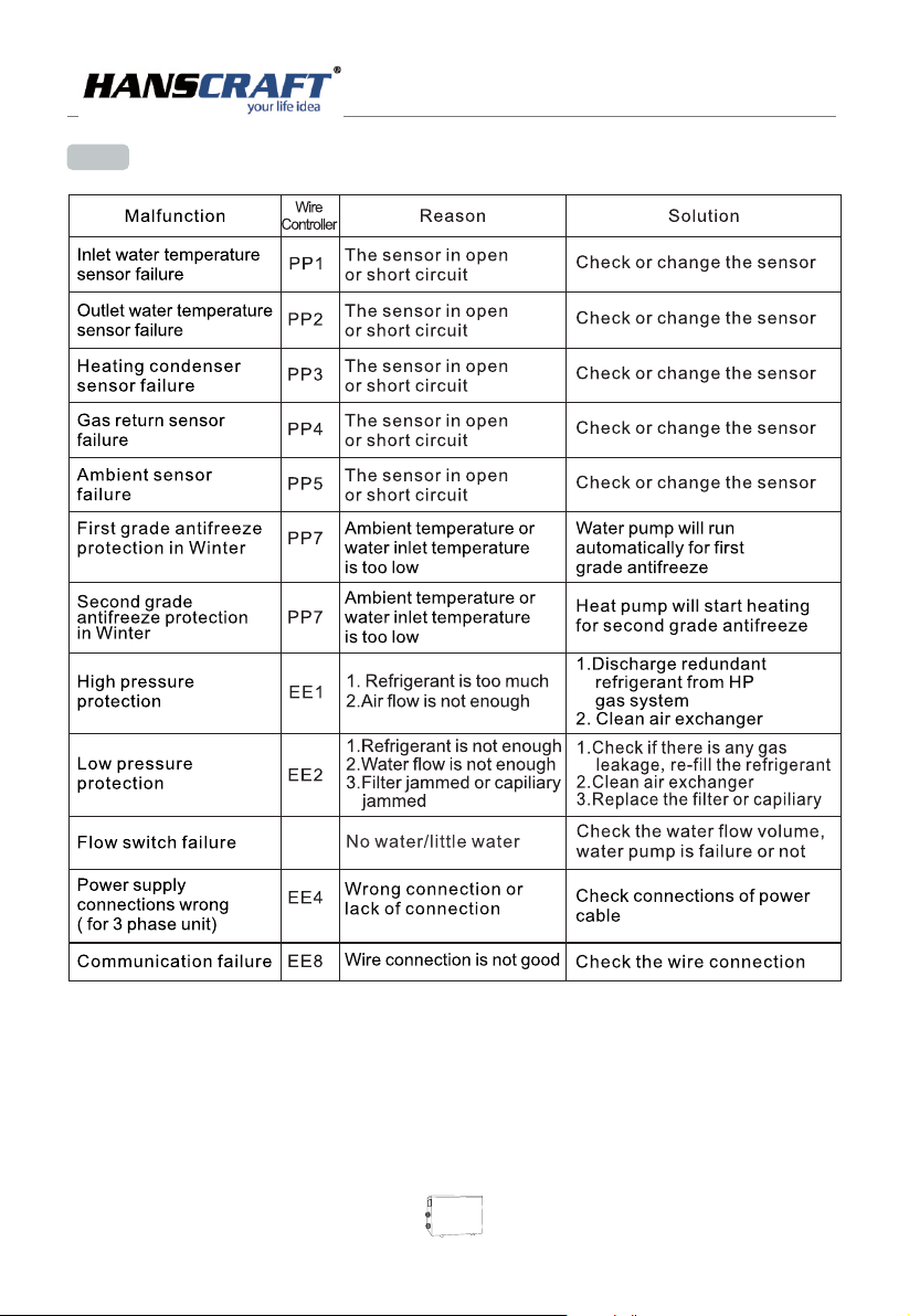
9.1 Error code display on LED wire controller
POO L H EA T P U MP
ON
Note: 1. If t he LE D dis pla y the h igh a nd lo w pre ssu re pr otection three time in h alf a n hou r,
2. If th e LED d isp lay t he " EE4 "
Above those matt er, yo u can c ut off the power and resta rt th e uni t aga in or t ake i t to ma int ain
15
Page 18
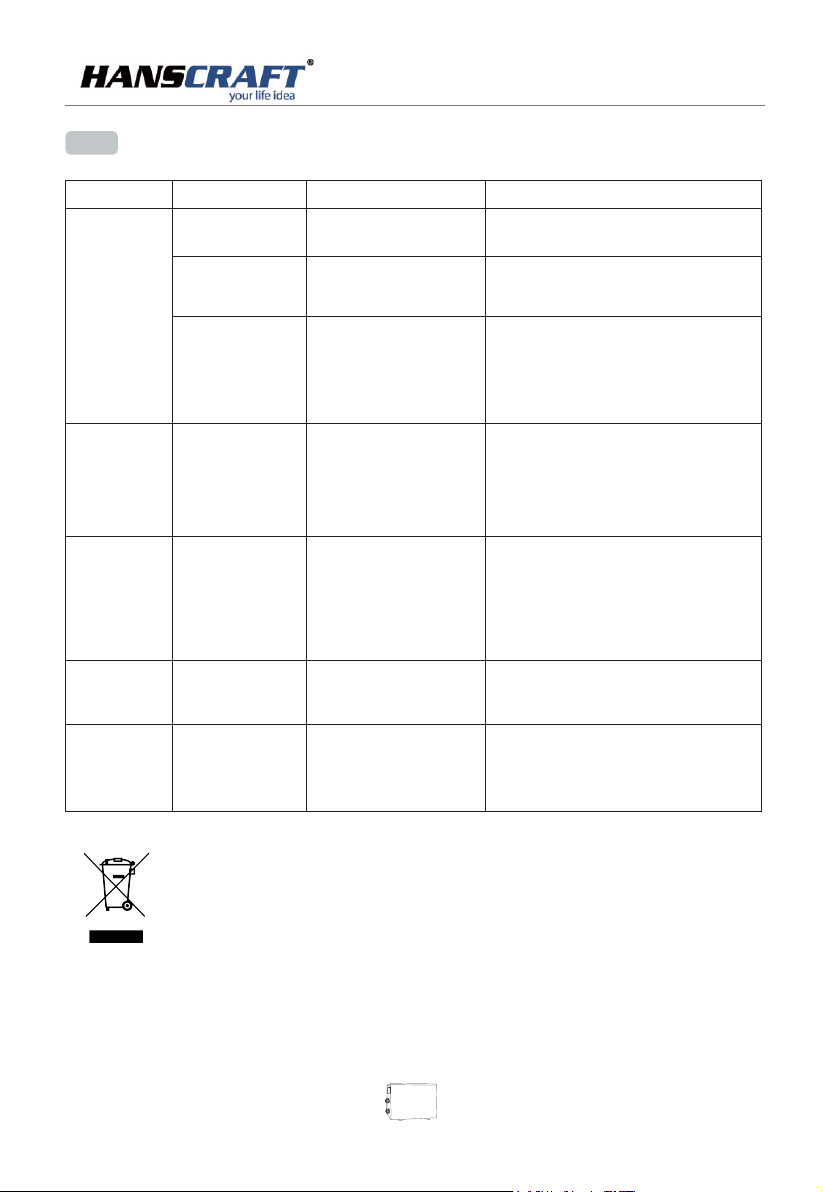
9.2 Oth er Malf uncti ons and Solutions ( No display on LED wire controller)
POO L H EA T P U MP
Malfunctions
Heat pump
is not running
Wat er
temperature
is cooling when
HP ru ns un der
heating mode
Short running
ater stains Wat er st ain s on
W
Too much ice
on evaporator
Observing
LED wire controller
no display
LED wire controller
displays the
actual time
LED wire controller
displays actual
the
water temperature
LED wire controller
displays actual
water temperature
and no Error code
displays
LED displays actual
water temperature
no Error
code displays
heat pump unit
Too much ice
on evaporator
Reasons
No power supply
Heat pump under
standby status
1. water temperature is
reaching to setting val ue
HP un der c ons tan t
temperature status
. Heat pump just start to run
2
3. under defrosting
1. choose the wrong mode
1. adjust the mode to prope r run nin g
2. figures show defects
3. Controller defect
1. fan NO running
,
2. air ventilation is not
enough
3. refrigerant is not eno ugh
1. concreting
1. No action
2. water leakage
1. air ventilation is
not enough
2. refrigerant is not eno ugh
Solution
Check cable and circuit b rea ker
if it is connected.
Startup heat pump to run
1. verify water tempera tur e set tin g
,
2. Startup heat pump afte r a few m inu tes
3. LED wire controller sh oul d
display “Defrosting ”
2. replace the defect LED w ire c ont rol ler ,
then check the status after ch ang ing t he
running mode, verifying the water inlet
and outlet temperatur e
3. replace defect main co ntr oll er
1. Check the cable connec tio ns be twe en
the motor and fan if ne ces sar y, it
should be replaced .
2. Check the location of he at pu mp un it,
and eliminate all ob sta cle s to ma ke go od
air ventilatio
3. Replace or repair the he at pu mp un it
2. check the titanium hea t exc han ger
carefully if it is any defect
1. check the location of he at pu mp un it
,
and eliminate all ob sta cle s to ma ke
good air ventilation
2. replace or repair the he at pu mp un it
,
n
In accordance to WEEE Directive (Waste from Electrical and Electronic Equipment Directive)
2002/96/EC this equipment should not be disposed of in the normal waste stream.
16
Page 19
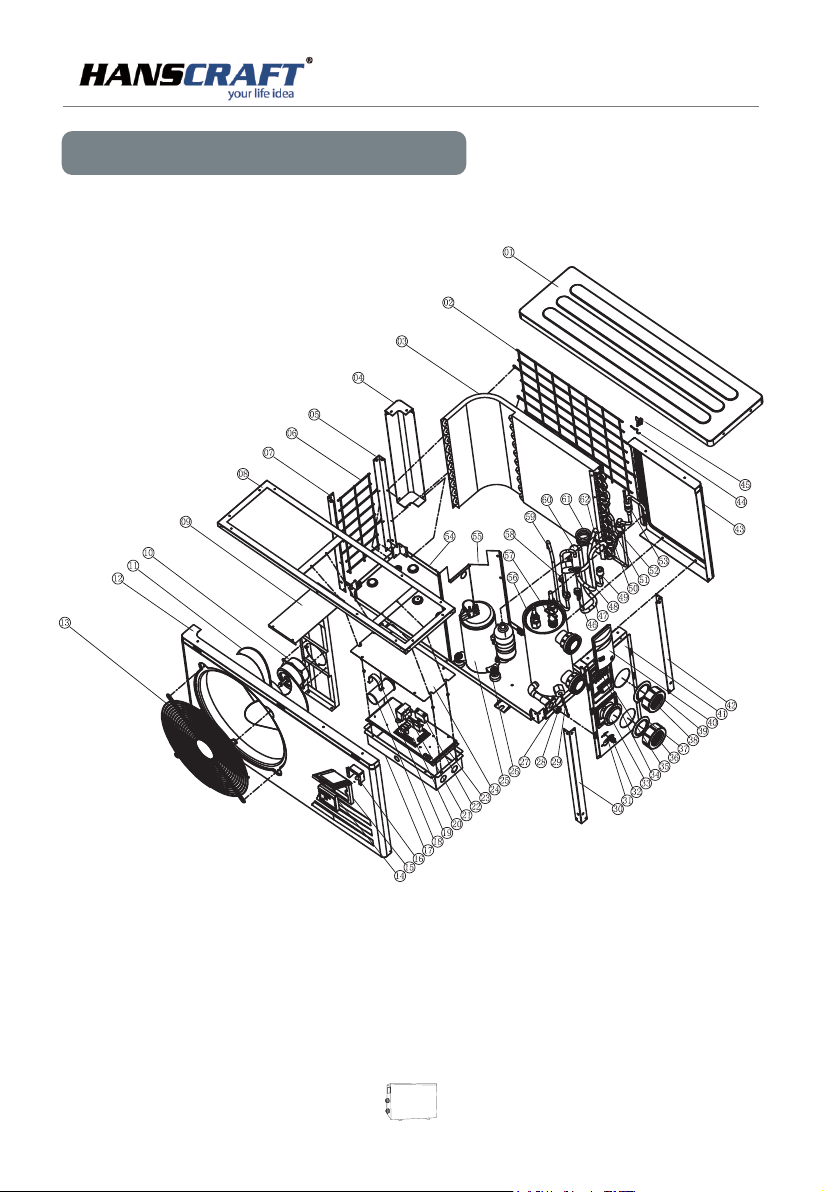
10.Exploded Diagram
POO L H EA T P U MP
17
Page 20
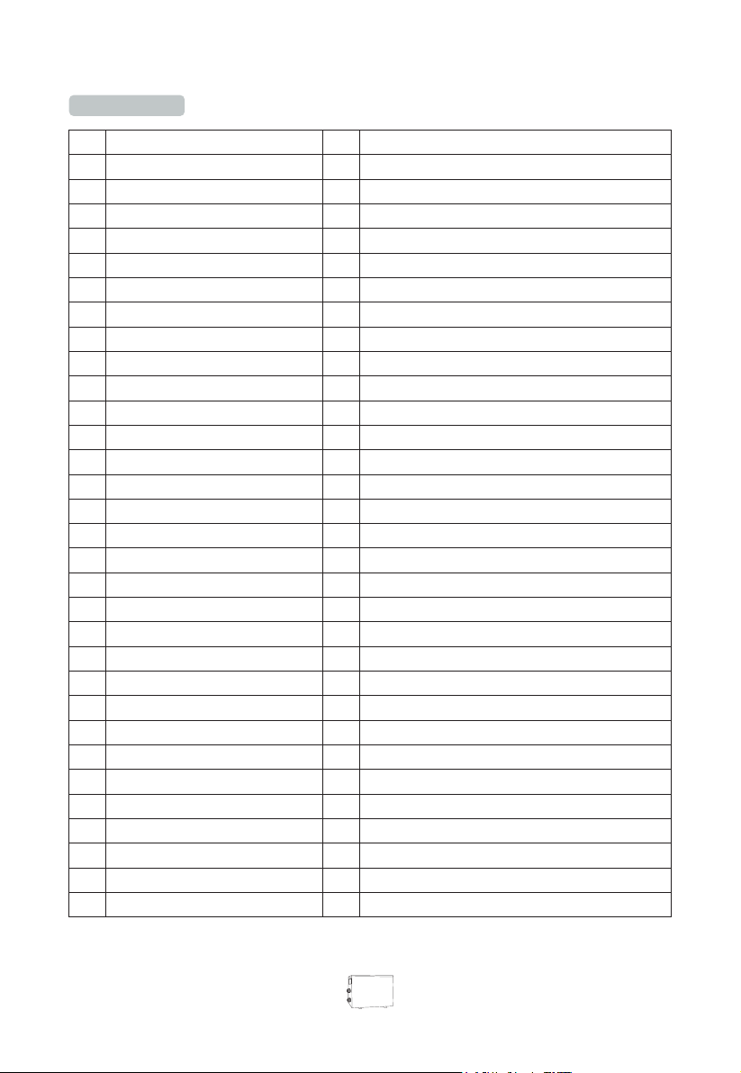
Parts list
Name of parts Name of parts
No. No.
top cover
1
back grill
2
evaporator
3
Pillar 1
4
5
Pillar 2
Left grill
6
Pillar 3
7
Upside frame
8
Fan bracket
9
Fan motor
10
Fan blade
11
Front panel-plastic
12
Front grill
13
Controller
14
15
Controller box
Fuse box
16
Electric box
17
Compressor capacitance
18
Capacitance clip
19
20
PC board
Transformer
21
Fan capacitance
22
23
Scale board
Electric box cover
24
Compressor
25
Compressor support
26
Inlet water temp. sensor clip
27
Choke plug
28
Inlet water temp. sensor
29
Pillar 4
30
31
Suction valve
32
33
34
35
36
37
38
39
40
41
42
43
44
45
46
47
48
49
50
51
52
53
54
55
56
57
58
59
60
61
62
Suction valve cover
Pressure gauge
Terminal block
Wiring clip
Water inlet cover
Retainer ring blue
Water outlet cover
Retainer ring red
Wiring cover
Right panel-plastic
Pillar 5
Back panel-plastic
Ambient temp. sensor
Ambient temp. sensor clip
Low pressure switch
Gas return pipe
Pipe(heat exchanger to 4-way valve)
Separator moudle
Cannula& clip of evaporator temp sensor
Evaporator temp. sensor
Gas collecting pipe
Filter moudle
Base tray
Isolation panel
Heat exchanger
Water flow switch
High pressure switch
Exhaust pipe
4-way valve
Capillary
Pipe(4-way valve to gas collector)
18
Page 21
NOTE
POO L H EA T P U MP
Page 22

 Loading...