

HANSA Press VKA-110 Operating Instructions Manual

Operating Instructions
1
VKA-110 Four-Ball Tester
In compliance with DIN 51350
1. Safety (from Page 5)
1.1 General information
1.2 Intended use
1.3 Safeguards of the VKA-110 four-ball tester
1.4 Transport
1.5 Occupational health and safety
1.6 Cleaning and maintenance
1.7 Electrics
1.8 Emergency stop
1.9 What to do if there is a fire
1.10 Environmental protection
2. Operation / “Option 4” Control Unit, Page 8
2.1 Switching on the machine
2.2 Switching off the machine
2.3 “Option 4” control unit
2.3.1 Options
2.3.1.1 USB interface
2.3.1.2 Zero-point weight
2.3.1.3 Additional options
2.3.1.4 Temperature control unit (TC)

2.3.1.5 More data points
2
2.3.1.6 Calibration
2.3.1.7 Testing without additional options
2.3.1.8 FTP server
2.3.1.9 WebVisu and web interface
2.3.2 Measuring
2.3.2.1 Measuring
2.3.2.2 Time-delayed recording
2.3.2.3 Stop parameter: measurement
2.3.2.4 Maximum torque
2.3.2.5 Unregulated / regulated
2.3.2.6 Step control
2.3.3 Status
2.3.3.1 Status
2.4 Jockey weight setting
2.5 Mounting additional weights
2.6 Ball holder
2.6.1 Inserting and loading the ball holder
2.6.2 Removing the ball holder
2.7 Standard ball cup and temperature-adjustable ball cup
2.7.1 Applying a load to the ball cup
2.7.2 Taking a load off the ball cup
2.7.3 Measuring microscope

2.8 Types of tests
3
3. Test Description, Page 22
3.1 Types of tests
3.1.1 What to do prior to each test
3.1.2 Standard short-time tests
3.1.3 Long-time tests
3.1.4 Testing materials
3.2 How to perform the tests
3.2.1 Conditions if the loads applied are low
3.2.2 Conditions if the loads applied are high
3.2.2.1 The wear scar diameter
3.2.2.2 The 2.5-second wear and tear delay time
3.2.3 Conditions if the loads applied are extremely high
4. Maintenance, Page 29
4.1 Spindle bearing
4.2 Ball holder
4.3 Standard ball cup and temperature-adjustable ball cup
4.4 Cutter holder
5. Installation, Page 30
5.1 Choosing a location
5.2 Floor requirements
5.3 Space requirements
5.4 Mechanical installation

5.4.1 Installation of the housing (pos. 1)
4
5.4.2 Installation of the writing utensil holder (pos. 19)
5.4.3 Balance scale bar (pos. 24)
5.4.3.1 Installation of the balance scale bar
5.4.3.2 The balance scale bar
5.4.4 Installation of the push rod (pos. 22), the plunger (pos. 20), the bearing
(pos. 64) and the rotary plate (pos. 21)
5.4.5 Mounting the stand for the “Option 4” control unit
5.4.6 Mounting the “Option 4” control unit
5.5 Electrical installation
6. Spare Parts and Wear Parts / Assembly Drawing, Page 33
7. Electrics/ Circuit Diagram, Page 33
8. VKA Training, Page 33

1. Safety
5
1.1 General information:
The VKA-110 four-ball tester incorporates state-of-the-art technology. It is safe to operate
if it is used as intended and the safety requirements are adhered to.
Though the design of the machine is state-of-the-art and safe to operate, there may still be
risks if:
the operating personnel is not properly trained or has not been properly instructed;
the machine is not used as intended;
the machine is not properly maintained or serviced.
Each person involved in installing, operating, maintaining, repairing and servicing the
VKA-110 must have read and understood these operating instructions and the safety
requirements.
The operator of the VKA-110 must properly train and instruct the operating personnel to
protect their health and safety. In addition the operator must train and instruct the
operating personnel in operating, servicing and maintaining the machine properly and
safely.
1.2 Intended use
The VKA-110 four-ball tester is used to mechanically test lubricants.
Permissible ambient temperature +5 to +40 ° C
Working temperature +5 to +150 ° C
Any use beyond this scope is considered improper. The operator / user of the machine is
liable for any damage caused by improper use.
Intended use includes observing the
safety information
operating information
servicing and maintenance information
provided in these operating instructions.
If you modify the electrics or mechanics of the VKA-110 four-ball tester, you will
forfeit the warranty.

1.3 Safeguards of the VKA-110 four-ball tester
6
Main switch Q1 0 = machine is OFF.
I = machine is ON.
Circuit breaker F3 0 = overload at power point 1 + 2 + ventilator
I = voltage at power point 1 + 2 + ventilator ON
Circuit breaker F1 0 = overload of the control voltage
1 = control voltage is ON.
Circuit breaker F2 0 = overload of the supply voltage for frequency converter/motor
I = supply voltage for frequency converter/motor is ON.
1.4 Transport
Unpack the VKA-110 four-ball tester immediately upon delivery and check for potential
transport damage. Check the separately supplied accessories for completeness.
You must notify us of any damage or missing parts within 10 days.
Only use sufficiently dimensioned transport and lifting slings and equipment (fork lift,
crane, belts).
1.5 Occupational health and safety
The VKA-110 four-ball tester has been designed and built in compliance with the EC
Machinery Directive, the relevant occupational health and safety regulations, and the
accident prevention regulations.
Caution! Spilled oil and lubricants make the floor slippery. If you slip while holding heavy
parts or sharp tools, you may sustain severe injuries.
Ensure that the workplace is well lit.
Keep your workplace tidy and clean to avoid accidents.
Beware of warm and/or hot objects (warning: the ball cup is extremely hot after wear tests
and weld tests have been carried out).
Wear protective gloves at all times.
Never reach into machinery and keep hands and fingers away from the moving spindle.
Loose clothing, long hair, necklaces, rings, bracelets, watches and ties may get caught up
in the spindle and/or ball holder.

1.6 Cleaning and maintenance
7
Clean and maintain the VKA-110 four-ball tester at regular intervals to ensure the
operational safety of the machine.
Switch off the main switch (Q1) of the four-ball tester before you start any cleaning and
maintenance works.
Ensure that the main switch (Q1) cannot be operated by unauthorised persons (padlock).
Even if the main switch (Q1) is turned off, some parts of the electrical system are live.
Always keep the control cabinet locked.
Do not clean the interior of the control cabinet. Risk of electrocution!
Warning: risk of explosion!
Oil mist-air mixtures may cause an explosion! Do not use compressed air or ozone to blow
off the VKA-110 four-ball tester.
Avoid open fire (smoking).
Take precautions to ensure that a fire can be extinguished quickly.
Do not use cleaning agents that attack synthetic material, rubber or varnish. They may
damage cables/wires, power points and displays.
Note that caustic cleaning agents such as, e.g., ethanol damage varnished coatings. Only
use cleaning agents suitable for varnish.
Cleaning agents may contain harmful substances.
Read the manufacturer’s information carefully.
1.7 Electrics
Only qualified electricians and/or persons properly trained in accordance with electrotechnical regulations are permitted to work on, maintain or repair the electrical system.
Even if the main switch (Q1) is turned off, some parts of the electrical system are live.

1.8 Emergency stop
8
Hitting the emergency stop button (kill switch) will slow the motor down to a complete
stop.
To re-start the VKA-110, click the "Acknowledging Emergency Stop" button on the
Touchdisplay under "Options". The VKA-110 is ready to start operating.
1.9 What to do if there is a fire
Use the circuit breakers to cut off the power supply.
Call the fire brigade.
Only use CO2 (carbon dioxide) to extinguish the fire.
1.10 Environmental protection
Make sure that the used-up testing and operating materials are properly disposed of.
2. Operation / “Option 4” Control Unit
The control unit has a Touchdisplay to operate and control certain functions. To operate
the control unit, lightly touch the Touchdisplay.
2.1 Switching on the machine
To switch on the VKA-110, turn the main switch (Q1) to ON/“I”.
Caution: risk of injury!
Keep hands and fingers away from the rotating spindle while the VKA-110 is in
operation.
If you need to work in the spindle operating range, make sure that the main switch (Q1) is
in the OFF/“0” position.
2.2 Switching off the machine
To switch off the VKA-110, turn the main switch (Q1) to OFF/"0".

2.3 “Option 4” control unit
9
The runtime system of the VKA-110 is based on Windows CE 5.0. It starts automatically
when the main switch (Q1) is turned to ON.
The “Option 4” control unit standard package comprises the following functionalities:
Evaluation of short-time test data at 0.1-second intervals
Weld point tests at rotational speeds of up to 6000 r/min
Motor torque display (numerical and graphic display)
Step control (freely programmable testing process)
Switch-off parameters: time or number of revolutions
Changing the rotational speed during the runtime
Automatic calibration of the rotational speeds
WebVisu + web interface (external operating option via PC, Ethernet interface)
FTP server (measuring data can be retrieved directly from a USB interface)
USB and Ethernet interface to evaluate data (e.g. in Excel)
The following additional options are available for the VKA-110 control unit:
Temperature display
Torque display for various ball cups
Test force display (assembly, see 5.4.4)
Vibration sensor
Additional options 1 - 3 are displayed numerically and graphically.
Additional option 4, vibration sensor, is displayed numerically.
The test data are transmitted via Ethernet or USB interface for evaluation in Excel.
Setting up the tester:
The VKA-110 comes default-configured.
You will only need to configure the network settings under the “end PLC” option if you
want to use the network functions of the VKA control unit.
Go to the Windows start menu, click on “Programs” and then “Control Panel”.
Enter the settings in “Network”.
Disconnect from the network before you start the VKA-110.
Connect the network cables only after the VKA-110 has been fully powered up to ensure
that your test results will be recorded.
Warning!
The “Option 4” control unit has copy protection.
Any attempt to copy the software will disable the control unit.
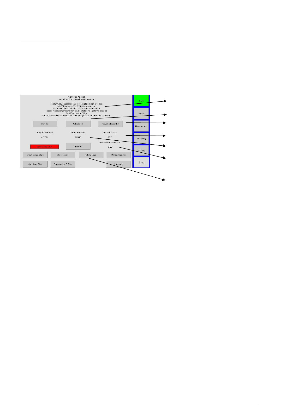
Operating panel:
10
additional option 4 only)
You can control all the VKA-110’s functions via the three windows listed below.
2.3.1 Options
Here you’ll find all the relevant control unit options.
about WebVisu anInformationd FTP server
Start/activation of the temperature control unit
(only when buying a circulation thermostat)
Step control activation
Safe working load in the “limited” mode
Control temperature before and after start
Switch-off limit if a vibration sensor is
used for the measurements (available with
Selection of the measurand, progress
display (available if upgrade to additional
options)
2.3.1.1 USB interface
The “USB Stick Status” field indicates whether the control unit has recognised a USB
stick. If the field is green, a measurement protocol will automatically be stored on the USB
medium when you start the VKA-110.
The system creates a file titled “VKA” on the connected USB medium and a sub-file for
each measurement, including date and name.
You can evaluate the data stored on the USB medium on an external computer.
Open an Excel file to automatically evaluate the data. If macros are activated, CVS (a file
format) will be automatically read in and diagrams will be created simultaneously. You
can adjust the macros individually to meet your company’s specific and format-specific
requirements.
The template is stored under \USBStorage\VKA\ in the control unit.
2.3.1.2 Zero-point weight
If various ball cups are used, the weight display may show deviations (due to the different
weights of the ball cups, temperature deviations or a deviating position of the push rod).
If you upgrade to additional option 3, we recommend you always click the “Zero-Point
Weight” (under options) when you chuck a new ball cup.

2.3.1.3 Additional options
11
Use the “Display Temperature”, “Display Torque” and “Display Weight” buttons
under “Options” to select the respective diagram display.
The diagram including progress is displayed under “Status”.
To make use of the function, you must have installed the respective additional options.
If you have not clicked a field, the display will show the torque or the rotational speed of
the motor (depending on the control mode of the frequency converter (FC)).
The respective measurand selected will be scaled automatically.
Temperature: 1°C * scaling factor/scale division (additional option 1)
Force transducer torque: 1nm *scaling factor/scale division (additional option 2)
Weight: 1kg * scaling factor/scale division (additional option 3)
FC torque: 1% * scaling factor/scale division (included in the standard package)
2.3.1.4 Temperature control unit (TC)
If the Julabo circulation thermostat is connected and switched on, the “Option” field will
display the “Start TC” and “Activate TC” buttons.
In “Activate TC” the temperature control unit starts operating when you click the start
button.
The motor will only power up when the temperature has reached the tolerance range
stated. There are two settings.
Temperature before engine start (e.g. 50°C) and Temperature after engine start (e.g. 60°C).
That is, the Taper roller bearing Holder (or Ball Cup) is heated to 50°C and then the
engine starts. The temperature is then further increased to 60 ° C control temperature.
2.3.1.5 More data points
If you set more data points, you will have more logging points per time unit in the
evaluation. When you measure the torque in short-time tests, you can set more
measurement points (0.1 seconds) under “More Data Points”.
2.3.1.6 Calibration
The VKA-110 comes default-calibrated.
You only need to carry out a calibration when you exchange the motor.
 Loading...