

Hansa-electronic HMG Operating Manual
HANSA
Gas burner HMG
G GB F ESP Art.-Nr.:
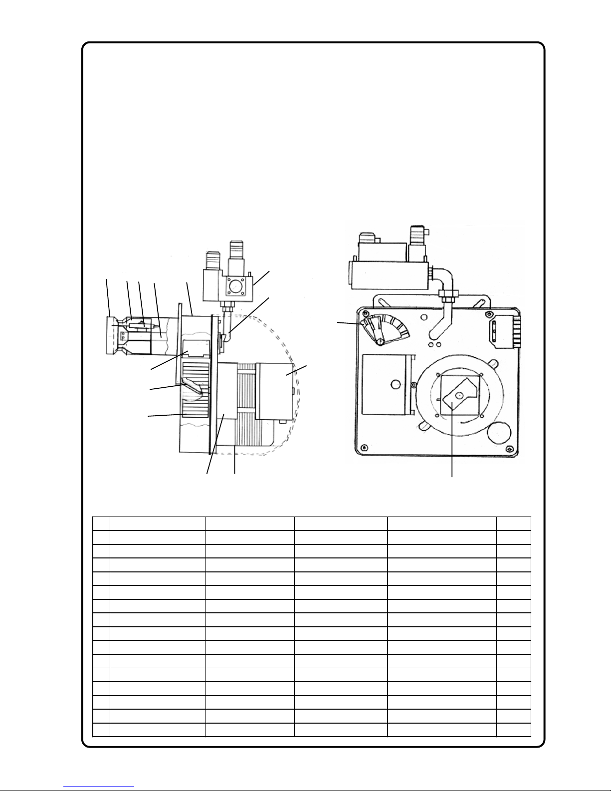
1
Flammrohr Flame tube Tube de flamme Tube de liama 1329
2
Stauscheibe Baffle plats Accroche flamme Deflector con 1331
3
Gas dü se 2510
4
Doppel-Zündelektrode Double ignition electrode Electrode d´allumage Deflector con 4174
5
Gehäuse Box 2010
6
Luftmengenregler Air regulator 1681
7
Gasdüsenstock kpl. Gas combustion head compl. Ligne de gicleur gaz compléte Cabezal Mezclador de gas compl.
8
Gasfeuerungsautomat Gas firing automat Boîte relais gaz automatique Cofre de Seguridad para Q-gas unit 3089
9
Motor 230V/50Hz/70W Engine 230V/50Hz/70W Moteur 230V/50Hz/70W Motor 230V/50Hz/70W 3434
10
Luftrad Fanwheel Ventilateur Ventilador 1675
11
Zündtransformator Ignition transformer Transformateur d´allumage Transformador de encendido 3174
12
Luftabschlußklappe air choke Volet d´air Válvula de aire 1673
13
Pressungverstellschieber Pressure slide lever Régulateur de pression Regulador de aire 1674
14
Gas-Kompakteinheit 3722
15
Luftdruckwächter 3762
1
2
3
4
5
6
7
8
9
10
11
12
13
14
15
Seite 1 von 5
Operating Manual
for HMG gasburner
Hansa burners are quality products. Expert installation, regulation/adjustment and servicing/maintenance
provided, our burners will work safely, reliably and economically for many years.
Before the assembly of the burner
the following steps have to be carried out:
Installation and Commissioning
This burner has to be installed and commissioned only by an expert. Therefore locally valid rules and
guidelines are to be strictly observed. He will bear responsibility for the appropriate laying out.
Norms
The following norms have to be considered for safe, environment-friendly and energy-saving running: DIN
4756 gas firing units, DIN 4788 part 2 gas burner with fan ventilation, DIN 4789 connection of atomizing
oil- and gasburner with fan ventilation on heat generators, VDE 0116 elektrical equipment of firing plants.
- Check, whether the heat generator is impermeable on its smoke gas side.
- In case of second hand heat generators the heating surfaces have to be clean in order
to achieve a good degree of effectiveness.
- Gas pipes have to be laid professionally and must be absolutely impermeable.
Content of box:
1 Gasburner HMG 2 Fixing screws M8
1 Operating-Manual mit 2 underlay discs
1 Flange gasket 1 Gasvalve
1 Plug with 7 poles 1 Conic case fixing screw
Assembly:
First you take the burner out of its box and dismantle the burner's bonnet.
Then you loosen the 4 outer screws of the burner case and take the upper part out of the lower part.
Now you fix the lower part to the boiler by means of the flange gasket (pic.1). Fit the upper part to the
lower part again and tighten the four outer screws. Now you assemble the gas valve, the gasket of
which you will also find in the transparent pack. Finally
assemble the gas supply to the gas valve. If gas supply and
electrical connection (euro-plug with 7 poles) is established, the
burner is operational. Please pay attention to the remark relating
to the air blockade on page 5.
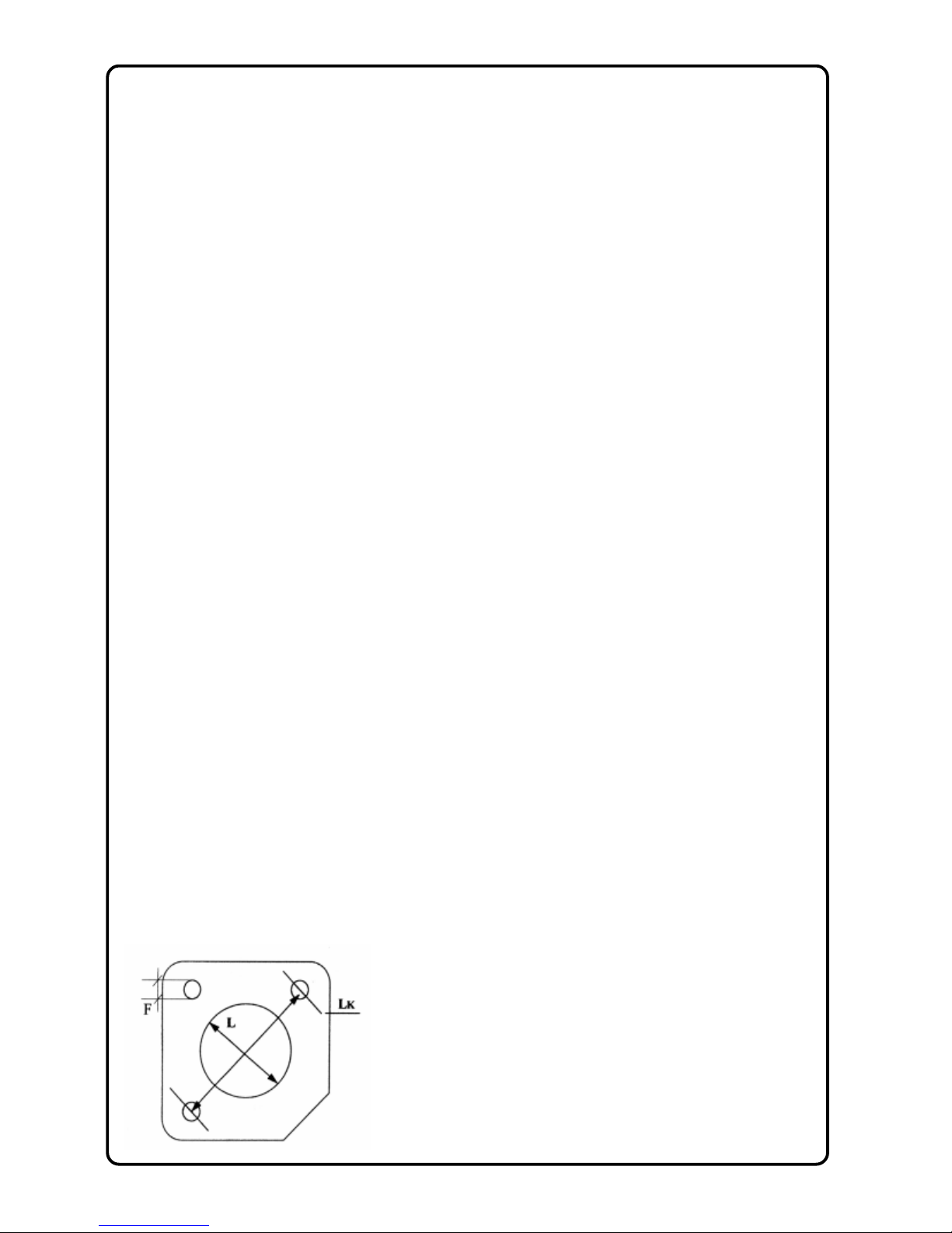
Picture1 flange gasket
LK=150
L = 81mm
F = 8,5
page 2 of 5
 Loading...