

Page 1
Service Handbook
By Product
T0022--3377
JJT
E11--000000
E
Version 1.0 2006/11/20
G
G
Page 2

Document Title. JT02-37E1-000G Service Handbook Revision. VER 1.0 Page No. 1 / 14
Table of Content
1. Product Disassembly SOP
1-1 Rear Cover and Stand Disas
1-2 Shielding and IO Cover Disassembly
1-3 Power Board Disassembly
1-4 Main Board Disassembly
1-5 Speakers Disassembly
bly1-6 Stand Bracket Disassem
1-7 IR Board and Power Button
1-8 Function Board Disassembly
1-9 Front Bezel Disassembly
y 1-10 Panel Bracket Disassembl
2.
Connection Diagram
3. Appendix
s
sembly
Board Disassembly
1
Page 3
Document Title. JT02-37E1-000G Service Handbook Revision. VER 1.0 Page No. 2 / 14
. Product Disassembly SOP
1
1-1 Rear Cover and Stand Disass
embly
Operation Procedure
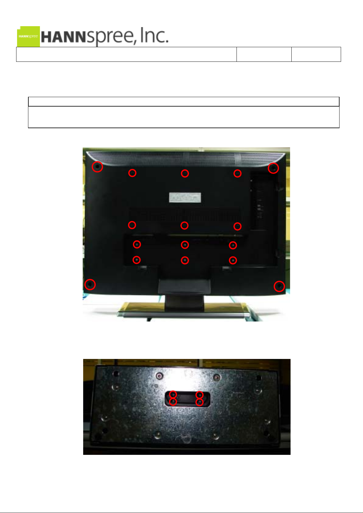
1. Loosen 16 screws from Rear Cover (Fig.1).
2. Loosen 4 screws from Stand, then remove the Stand (Fig.2).
3. Remove the Rear Cover.
Fig.1
Fig.2
2
Page 4
Document Title. JT02-37E1-000G Service Handbook Revision. VER 1.0 Page No. 3 / 14
1-2 IO Cover and Shielding Disassembly
Operation Procedure
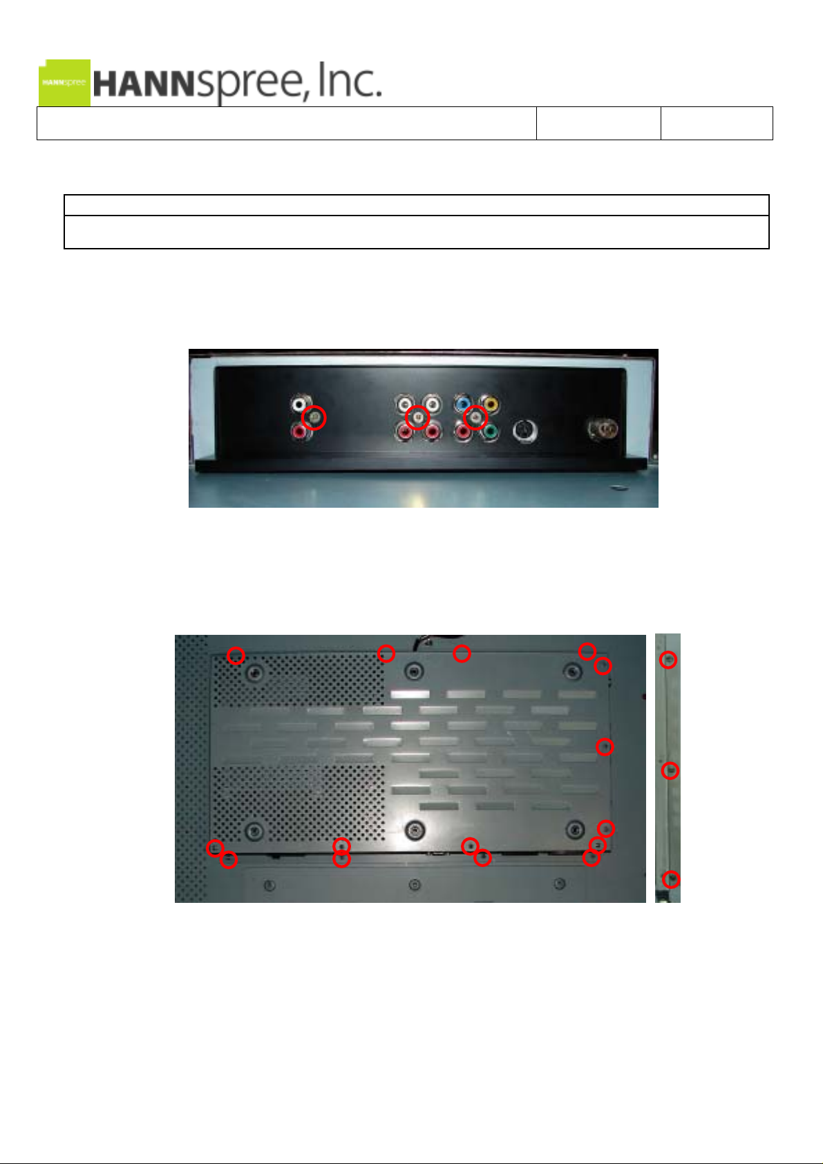
1. Loosen 3 screws from IO Cover, then remove the
2. Loosen 18 screws from Shielding and brackets, then remove the Shie
IO Cover (Fig.1).
lding and brackets (Fig.2).
Fig.1
Fig.2
3
Page 5
Document Title. JT02-37E1-000G Service Handbook Revision. VER 1.0 Page No. 4 / 14
-3 Power Board Disassembly
1
Operation Procedure
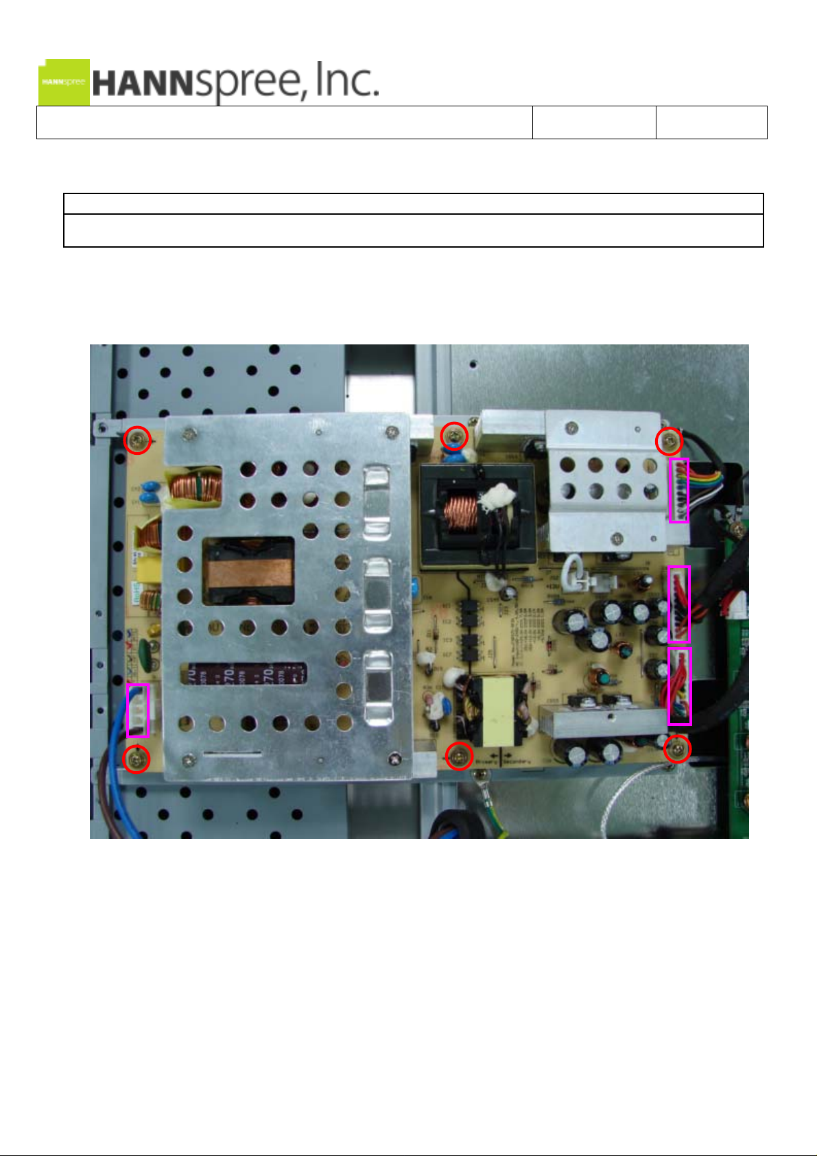
1. Disconnect all wires from Power Board (Fig.1).
it (Fig.1). 2. Loosen 6 screws from Power Board then remove
Fig.1
4
Page 6

Document Title. JT02-37E1-000G Service Handbook Revision. VER 1.0 Page No. 5 / 14
1-4 Main Board Disassembly
Operation Procedure
1. Disconnect all wires from Main Board, loosen 6 s d then remove it (Fig.1). crews from Main Boar
Fig.1
5
Page 7

Document Title. JT02-37E1-000G Service Handbook Revision. VER 1.0 Page No. 6 / 14
1-5 Speakers Disassembly
Operation Procedure
1. Loosen 8 screws from left/right speakers, then remove them (Fig.1).
Fig.1
6
Page 8

Document Title. JT02-37E1-000G Service Handbook Revision. VER 1.0 Page No. 7 / 14
1-6 S
tand Bracket Disassembly
Operation Procedure
1. Loosen 2 screws from Stand Bracket then remove it (Fig.1).
Fig.1
7
Page 9

Document Title. JT02-37E1-000G Service Handbook Revision. VER 1.0 Page No. 8 / 14
1-7 IR Board and Power Button Board Disassembly
Operation Procedure
1. Remove all wires from IR Board and Power Butto
2. Loosen 4 screws from IR Board and Power Button Board, th
n Board.
en remove them (Fig.1).
Fig.1
8
Page 10

Document Title. JT02-37E1-000G Service Handbook Revision. VER 1.0 Page No. 9 / 14
1-8 Function Board Disassembly
Operation Procedure
1. Loosen 2 screws from keypad module, loosen 1 screw from wire (Fig.1).
2. Disconnect the wire, loosen 2 screws from Function Board (Fig.2).
Fig.1
Fig.2
9
Page 11

Document Title. JT02-37E1-000G Service Handbook Revision. VER 1.0 Page No. 10 / 14
1-9 Front Bezel Disassembly
Operation Procedure
1. Loosen 6 screws from Panel Bracket, then remove ). the Front Bezel (Fig.1
Fig.1
10
Page 12

Document Title. JT02-37E1-000G Service Handbook Revision. VER 1.0 Page No. 11 / 14
1-10 Panel Bracket Disassembly
Operation Procedure
1. Loosen 10 screws from Panel Bracket (Fig.1).
2. Loosen 14 screws from Panel (Fig.2).
Fig.1
Fig.2
11
Page 13

Document Title. JT02-37E1-000G Service Handbook Revision. VER 1.0 Page No. 12 / 14
2. Connection Diagram
12
Page 14

Document Title. JT02-37E1-000G Service Handbook Revision. VER 1.0 Page No. 13 / 14
3. Appendix
13
 Loading...