

Page 1

Liquid Crystal Display
Television
GT02-32E1 / GT03-37E1
SERVICE MANUAL
Page 2

I
Preface
All rights reserved. No part of this publication may be reproduced, transmitted, transcribed, stored in
a retrieval system or translated into any language in any form or by any means, electronic, mechanical,
magnetic, optical, chemical, manual, or otherwise, without the prior permission of the company.
Disclaimer
We make no representations or warranties, either expressed or implied, with respect to the contents of this
document, and specically disclaims any warranties, merchantability or tness for any particular purpose.
Further, reserves the right to revise this publication and make changes in the contents without obligation to
notify any person of such revision or change.
All rights reserved
VGA and XGA are registered trademarks of International Business Machines Co. Inc.
Product safety notice
Many electrical and mechanical parts in this product include specic, safety related characteristics. These
characteristics may not be immediately obvious by visual inspection and the protection these components
offer can not necessarily be obtained using replacement components with the same voltage or power ratings.
Replacement parts with specific safety characteristics are identified in this manual and its supplements.
Electrical components having such features are identied by shading on the schematic diagram and in the
parts list. Before replacing components, read the parts list in this manual thoroughly.
The use of substitute parts which do not have the same safety characteristics as those indicated in the parts
list may cause electrical shock, re, x-ray emissions, or other hazards.
Service notes
1. When replacing circuit boards or components, clamp the lead wires to the terminals before soldering.
2. When replacing a high power resistor (oxide metal lm resistor) on a circuit board, keep the resistor at
least 10 mm (0.5-inch) from the circuit board.
3. Keep leads and wires away from high voltage and high temperature components.
4. If any fuse in the product is blown, replace it only with the correct fuse specied in the parts list.
Handling of broken glass and liquid crystal leakage
If the LCD is damaged, liquid crystal leakage may occur and the glass may shatter into small pieces. Do not
touch the broken glass or liquid crystal which is toxic. In addition to possible cuts resulting from broken
glass, toxic leakage may cause skin irritation or poisoning. If liquid crystal enters your eyes or mouth, you
should immediately rinse with clean water and consult a doctor.
Important safety information
1. Read all these instructions.
2. Save these instructions for later use.
3. Unplug this television set from the wall outlet before cleaning.
4. Do not use accessories not recommended in the user manual as they may damage the product.
5. Do not use this product in wet locations such as near a bathtub, washbowl, kitchen sink, laundry tub,
swimming pool, or in a wet basement.
Page 3

II
6. Do not place this product on an unstable cart, stand, or table. The television receiver may fall and cause
serious injury as well as possibly damaging the product. Use only with a cart or stand recommended
by the manufacturer or sold with the product. Wall or shelf mounting should follow manufacturer’s
instructions and only use a mounting kit as recommended by the manufacturer.
7. Blocking the ventilation holes can cause overheating and re. Take care not to block any ventilation holes
when siting the television close to walls or other objects. Never install this product in a closed cabinet or
bookcase unless sufcient ventilation is provided.
8. This television should be operated using only the type of power source indicated on the label and in the
user manual. If you are unsure what your home power supply is, you should consult the Power Company
or talk to your television dealer.
9. This television is equipped with a plug designed to t only one way in the power socket. The earth pin is
an important safety feature of the plug. If the plug does not t your outlets or your outlets do not include
a hole for the earth pin, you should consult a qualied electrician about replacing the socket.
10. Do not rest anything on the power cord and do not allow the power cord to lie in a position where it is
likely to be stepped on or tripped over.
11. Follow all warnings and instructions marked on the television receiver.
12. During thunderstorms and when the television is unused for extended periods of time, you should
unplug the power cord from the outlet and disconnect the antenna.
13. External antenna systems should be sited away from overhead power lines and away from electrical
circuits. Extreme caution should be exercised when erecting an outside antenna. Touching overhead
power cables can be fatal.
14. Do not overload power outlets or extension cords as re or electric shock can result.
15. Never push anything into the television through the ventilation slots as they may come into contact with
high voltage elements of the device and cause electric shock or re. Take care never to spill liquids into
the product.
16. Servicing of this product should only be carried out by qualied service technicians.
17. Unplug this product from the power source and consult a qualied service technician in the following
cases:
• The power cord is damaged or frayed.
• Liquid is spilled into the television.
• The television is exposed to rain or water.
• The television does not operate as the user manual describes. In this case, use only the controls
covered by the operating instructions. Improper adjustment of this equipment using controls not
covered in the user manual may result in damage to the product that may require extensive work
by qualied technicians to rectify.
• The television or cabinet is damaged.
• The television shows a change in performance that indicates a need for servicing.
18. When replacement parts are used, ensure that the technician uses only parts recommended by the
manufacturer. Unauthorised replacement parts may cause a re or electric shock.
19. After servicing, ensure that the technician performs routine safety checks to determine whether the
television is in a safe operating condition.
20. When moving this equipment, care should be taken to prevent damage due to dropping, falling or
impact.
Page 4

III
Introduction....................................................................................................................1
Specicitions................................................................................................................................2
Front View...................................................................................................................................3
Rear View.....................................................................................................................................4
Block diagram..............................................................................................................................5
Service mode...............................................................................................................................10
Assembly and disassembly procedure...................................................................................17
Disassembly..........................................................................................................................17
Reassembly...........................................................................................................................19
Exploded view..........................................................................................................................20
Printed circuit boards..............................................................................................................24
Power circuit board.............................................................................................................24
Main board...........................................................................................................................25
Digital board........................................................................................................................26
Trouble shooting .......................................................................................................................29
Handing and placing methods................................................................................................32
Schematic Diagrams.................................................................................................................33
Table of contents
Page 5

1
This service manual covers the LCD TV and is intended for the use of qualified service engineers only.
Service and repair of this product by unqualied persons may result in permanent damage to the product or
personal injury and should not be attempted.
This manual includes:
.A block diagram of the LCD TV
.An explanation of theory of operation
.An explanation of the service mode to enable you to adjust the internal settings
.A step by step guide to assembly and disassembly of the product
.A complete parts list for the product
.An exploded diagram of the product
.Pictures of the printed circuit boards
Introduction
Page 6

2
Specications
Display I/O ports
Active screen size 32,37 inchs SCART 2
Aspect ratio 16:9 YPb input (Y Cb/Pb Cr/Pr) 1
Resolution 32”,37” 1366*768 S-IN input 1
AV input 1
viewing angle 32” 176/176 PC input 1
37” 176/176 Audio jack input(L/R) 5
PC audio in 1
Tuner
Anttena system 1
Number of tuners 2 Audio out (L/R) 1
Standards B/G,D/K,L/L,I HDMI input
2
Number of programmes 99 Digital Anttena system
1
Colour system PAL,SECAM
Other
Video
User manual √
Progressive scan √
2:2 /3:2pull down √
Dimensions(HWD) 32” 650mmx820mmx230mm
Noise reduction √
37” 730mmx960mmx280mm
Audio
Speaker 2
Packing size(HWD) 32” 780mmx960mmx320mm
Audio power 10w+10w
37” 870mmx1130mmx370mm
Stereo /NICAM √
Audio mode 3
Gross weight 32” 26.5KG
Audio volume level √
37” 38.5KG
surround sound √
Function
Power consumption
32” operating: 190W
Channel return √
standby<2.5W
Channel edit √
Power consumption
37” operating: 220W
Channel name and sorting √
standby<2.5W
ZOOM mode 6
Resolution
Video mode 4
Supported 1280 x 1024 @ 60Hz
Audio setting √
1024 x 768 @ 60/75Hz
timer setting √
1280 x 768 @ 60Hz
1280 x 720 @ 60Hz
(PC reference mode)
Teletext √
1360 x 768 @ 60Hz(PC reference mode)
teletext pages 1000
800 x 600 @ 60/75Hz
OSD languages 12
640 x 480 @ 60/75Hz
(PC reference mode)
No signal auto off 15 min
720 x 400 @ 70Hz
Page 7
3
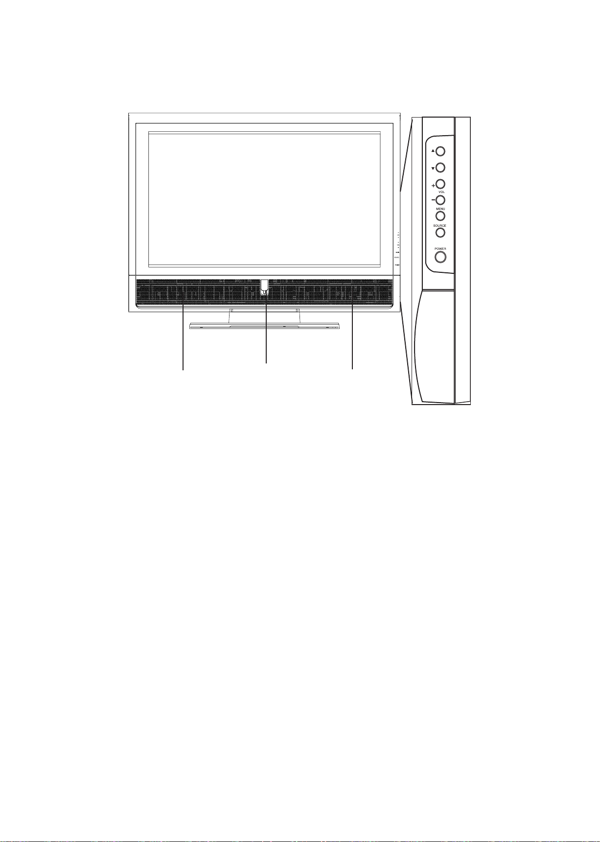
Front view
CH/
Increases or decreases channel numbers.
VOL/
Increases or decreases the volume.
MENU
Press the button to enter On Screen Display (OSD).
SOURCE
Switch among the input source .
POWER
Turn the TV set ON or OFF.
Speaker
Speaker
Power Indicator
LED
CHANNEL
VOLUME
Page 8
4
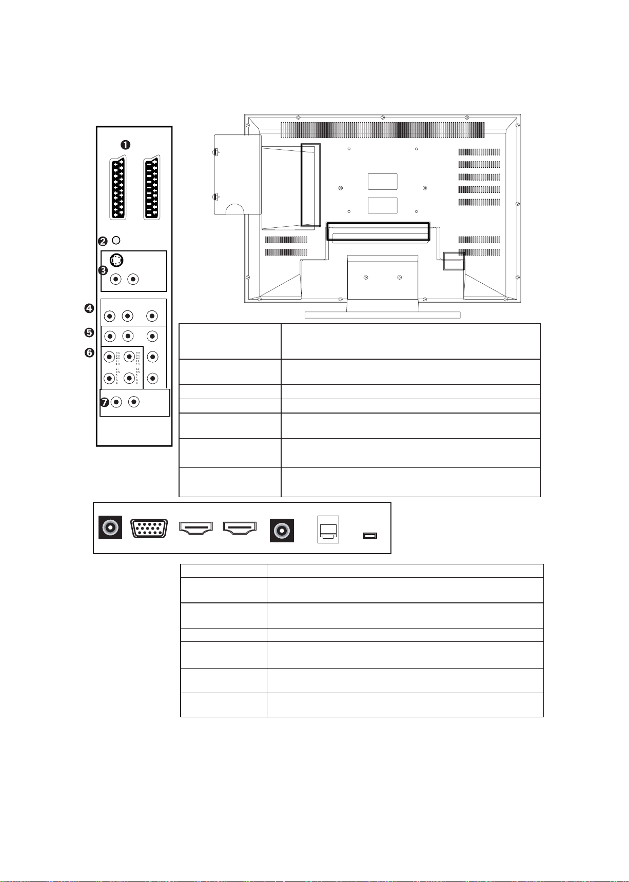
Rear view
SCART 1/SCART 2
Connects to the scart output of your A/V device (SCART
1 is always RF out, SCART 2 is optional of CVBS out ,RF
out and SCART CVBS out.)
PC AUDIO IN
Connect to the audio output of your PC or portable
computer.
S- IN
Connect to the S-Video output jack of your S device
.AV IN
Connect to the A/V output jack of your A/V device
COMPONENT IN
Connect to the component output jack of your component device
H DMI ANALOG
AUDIO IN
Connect to the audio output of your PC or A/V device when using HDMI port.
AUDIO OUT
Connect to the audio in put jack of your A/v device.
Adjustment can be control by Volume KEY
ANALOG ANT
Connects to your TV antenna or coaxial cable from local TV
PC -IN
Connect to the VGA output of your PCor portable
computer.
HDMI-IN 1/2
Connect to the HDMI output of your PC or portable
computer or A/V device.
DIGITAL ANT
Connects to your coaxial cable from local TV
DIGITAL
AUDIO IN
Connect to audio device which with RCA jack by optical audio cable .(32” no support)
SERVICE PORT
For manufacturer use only. Incorrect using may damage
system.
AC -IN
Connect to the AC outlet.
S
C
A
R
T
1
PC AUDIO IN
S- IN(vedio)
R
L
(red) (white)
(audio)
(red)
(white) (
yellow)
R
L
V
AV- IN
R
L
(red) (white)
AUDIO OUT
(red)
(blue) (green)
(red)
(red) (red)
(white white) (white)
R
R
R
Cr/Pr
Cb/Pb
V
C
O
M
P
O
N
E
N
T
I
N
S
C
A
R
T
2
Page 9
5
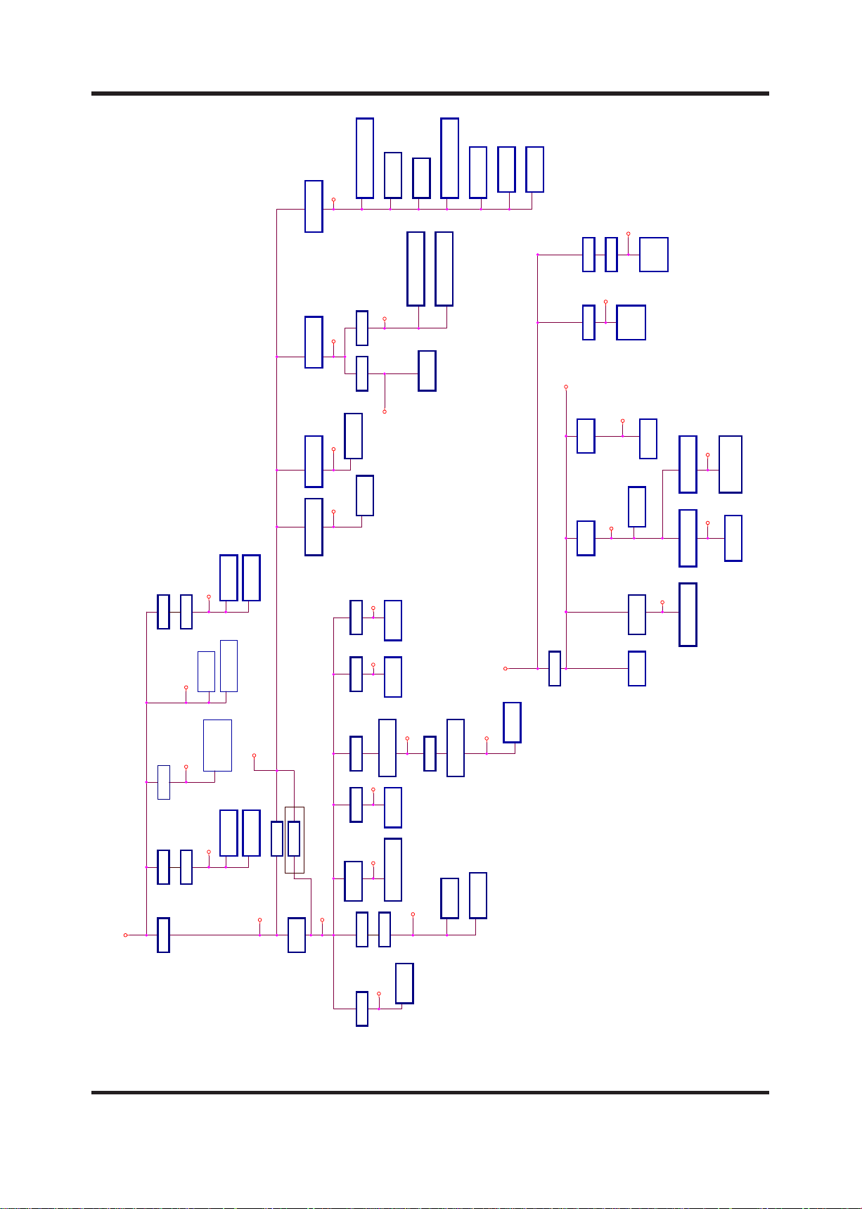
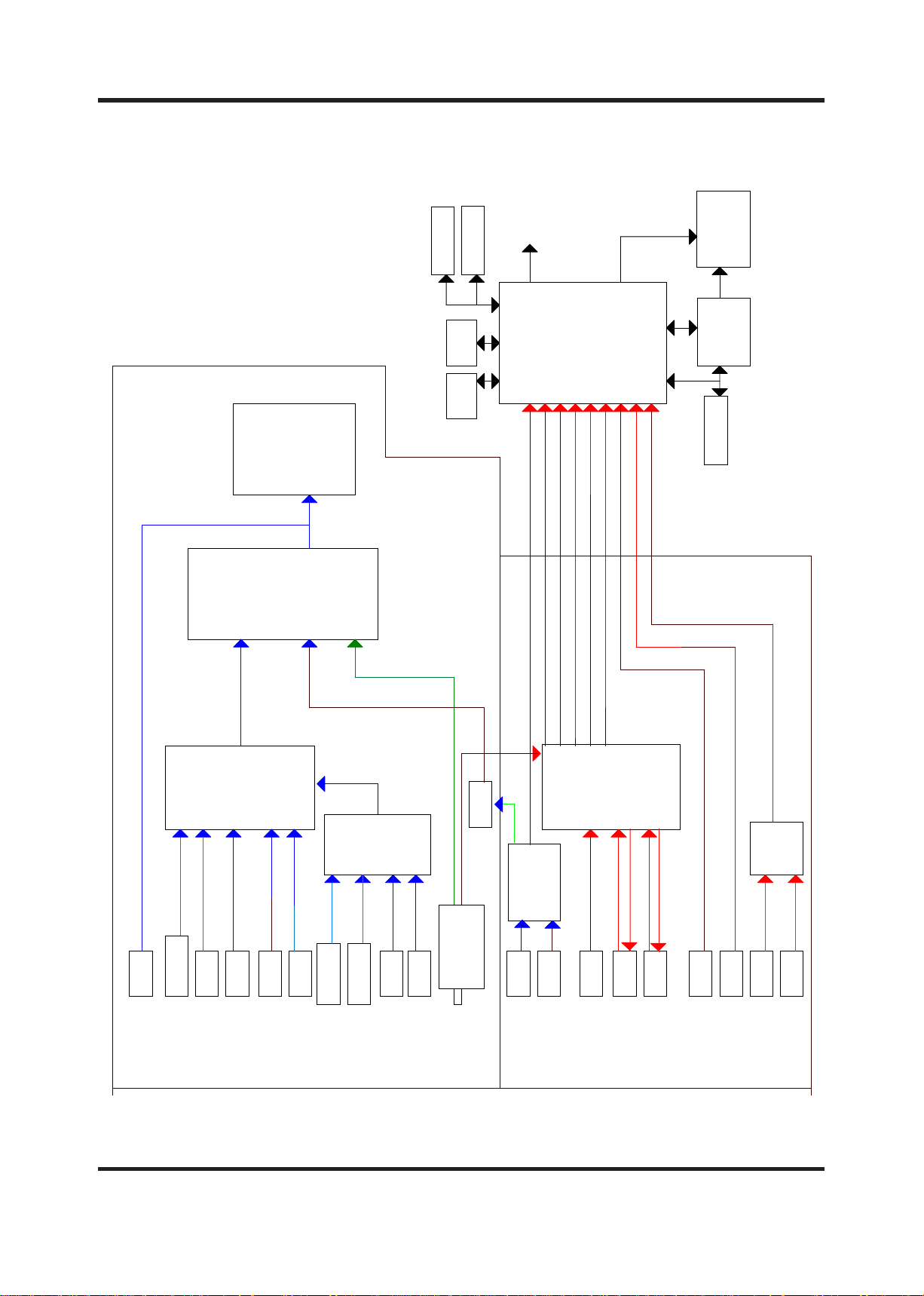
Block diagram
Circuit Description
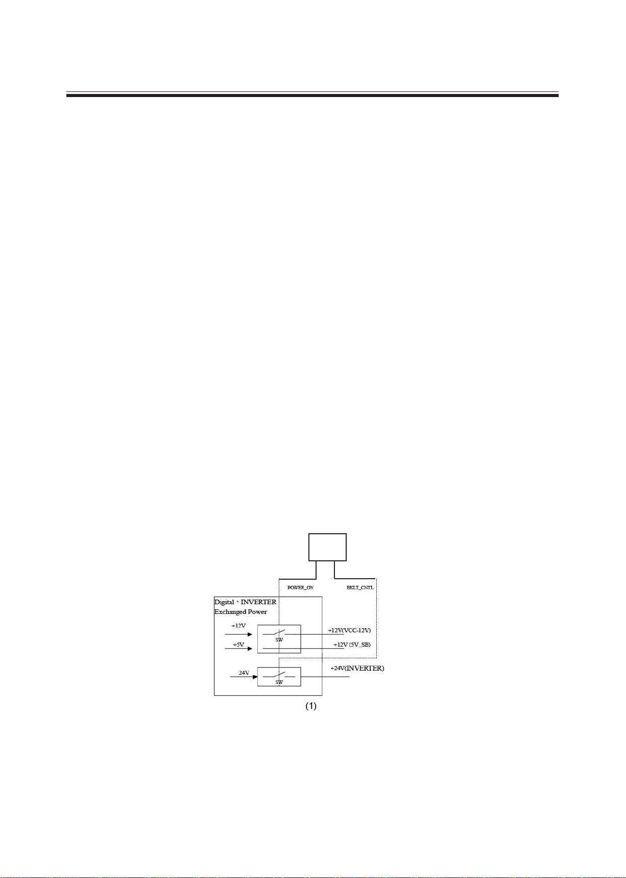
Power Circuit:
Switching power Model provide this machine 3 batch power: +12V, +5V and +24V. +5V
is Stand-By power, with +12V provide every circuits in main board needed power .+24 is
back light power.
A.Cold-Opening Mode:
•When connect with AC, switching power produce +5V voltage immediately
(circuit mark Vsub) and provide U1(PW106B) the needed stand-by voltage to
turn on the machine
•This machine is in Stand-By Mode now.
B.Stand-By Mode(+5V)
•W h en t hi s ma c hi ne is in St an d- B y mo de , onl y U1 (P W 10 6B ) and
U25(EN29LV160) keep workings, U1 enter power saving mode, so the system
can assure the consumption power is < 2.5W in Stand-by Mode.
C.Power ON Mode
•When the system receives the start order by Power Key of the remote control
or Power ON/OFF of the control panel, it enter power ON mode.
•When switching power receives the start order by U1, via Q23 to control
Switching power Model provides +12V and +24V voltage . .
•After every batches of digital board process Power ON procedure,U1 via
BKLTPWER(=H) to start Inventer and light the back light.
•The Block Diagram shows the voltage of Power ON Mode and IC.
U1
PW106B
Page 10
6
73U_WSCCV
23U_WSCCV
ACCV
BA52V 52DDV
NI21V
busV
pu5V
81V
A33V
CCVH
RIbusV
52V 33V
IMDH33V
XR81V
CCVCP
CCVLENAP
VTDH5V
WSCCV
5V
5CAD
21V
8V
PMA21V
TCCVUA5V
CCVLENAP
A9V
1CCVH
V21_TBVD
921L
521L
621L
AM001AM001AM001
Am006
Am006
081L
2U
033V5IP
931L
23U
F6667AB
A4
A4
Am05
Am05
99L321L
1CIA 3.3-711
04U
1CIA 3.3-711
81_13U
JDA-6971TA
1U
601WP
1U
11U
601WP1U
62U
-RDD M821-61*M8
601WP
8U,71U
41G1CVL47
SDVL redaeH tupuO
52_03U
JDA-6971TA
3209IIS
12U
F23L42RB
1U
601WP SLAREHPIREP
92U
853ML
15U
1UT
6121QF
Am007
A3
Am005
A3
A6
Am005
18L
81U
9002AAT
61U
A80D87
51U
G5143PSM
72Q
7J
SDVL rotcennoC
M5344PA
421L
74L
31D
21U
4334SC
81U
31U
B20CL42
A5
Am005
A6
J04C4695MS
3P
02U
13D
Am05
M5344PA
22U
1 IMDH
83D
91Q
32U
621G1CVL47
81L
Am05
41CVL47
7J
Am006
Am006A2.1A0.1
A2
A2
Am006
AM001
Am05
44L
71U
41G1CVL47
93U
1CIA 8.1-711
1CIA 3.3-711
52U
M61_HSALF
92L
6U
A12CL42
SDVL rotcennoC
71Q
M5344PA
7J
91U
601WP
1U
72U
-RDD M821-61*M8
G5143PSM
51U
71U
0.5-A711DL
1U
UPC 601WP
RENUT
33U
0.5-A711DL
Am005
23U
A90D87
A75851NA
2U
Am004
9U
CB2504UB
43U
B20CL42
3P
Am05
2 IMDH
57D
102L
791L
891L
A2
302L
TBVD
281L
ELUDOM
EERT REWOP
Page 11

7
Antenna Circuit:
• Tuner FQ1216 receive the signal come from CATV or antenna RF PAL/SECAM signal
and demodulate image composite signal (signal mark TV 1) and audio medium frequency
signal (signal mark SIF1).
• Image composite signal (signal mark TV 1)
• Via Q6 Video buffer(signal mark TV1_EX) than enter U37 Scaler IC EX-52 CVBS1 in-
put jack (Pin242) directly. Switches with other input signals in inner switch circuit.
• Other one via Q9 buffer (signal mark TV1_SW) enter U22 SCRAT SWITCH IC
CXA2125 TV_CVBS VIN_15 input jack (Pin23) and switch with other input signals to process POP/PIP signals selection .
• Audio medium frequency signal (signal mark TVAF1), transmits to U48 MSP3410/
MSP3411 SOUND PROCESSOR PIN50 to demodulate audio IF and stereo. Than
switches signal source with other Audio Source (PC AUDIO, U22 SCART SWITCH IC CX-
A2125Q AUDIO OUT). PIN 20,21 outputs Audio R/L signal, and amplify by OP AMP U57
U59 TL082 then enter D-amplier U66 TPA3004 output.
AV (Video) Input circuit (TV,AV,S,SCART,YUV(YPbPr),PC,HDMI:
• AV in/output signal includes:TV,AV,S,SCART,YUV(YPbPr),PC,HDMI
• TV:Image composite signal output from tuner and separate into two way:one enter U2
AN15857; Other one be amplied in Q46,Q47 to be the video output of SCART1.
• AV :the image signal transmit to U2 AN 15857.
•
Image composite signal of TV,AV,SCART amplify 2 times in U2 then transmits to U1
PW106B Via U2 Pin54 process decoding procedure .
• S(Y/C):The video signal input U1 PW106B..
• SCART :SCART 1 and SCART 2 are full SCART, SCART 1 is always TV out ;SCART 2 is monitor
OUT.
• Y signal ,C signal and RGB signal transmitting and switching in U2 AN15857 .Y signal output
from U2 PIN52; C signal output from U2 PIN 56; RGB signal output from U2 PIN62, PIN 60 ,PIN64
,then decode signal in U1 PW106B.
• Component (YUV/YPbPr)video signal transmits and process decode procedure in U1 PW106B.
Component signal is YUV,Y content Horizontal sync signal and Vertical sync signal.
• VGA signal includes: R、G、B (Horizontal sync signal) (Vertical sync signal),
• The EDID code of VGA store in U6 24LC21A, it’s can burning DATA via jack about 128 bytes.
• TMDS of HDMI 1 ,HDMI 2 decode into R.G.B signal in U11 SII9023 then process image quality
and scaler procedure in U1 PW106B.
• CM1~CM8 are govern EMI element. U4,U35 Rclamp 0514 is ESD
• EDID of HDMI store in U3,U34 24LC02B and each one content 256 bytes date.
• U1 PW106B is the most important IC in this system. Main function are:
a.CPU:Microprocessor
b:ADC:Switch analog signal into digital signal.
c.Video Decoder (3DComb lter:Decoding HDTV(1081i),NTSC,PAL,SECAM signal.
d.Deinterlacing:Switches not progress screen into progress screen. EX 1080i switches to 1080p
e.Scaler: Scaler rate .Switches different resolution which from input source in to panel resolution.
f:OSD:Offer 256 color OSD
g:Image Management : EX, sharpness DLTI, DCTI...
h:Display output port:Switches signal ib to LVDS signal which panel need.
Page 12

8
AV Input Circuit(Audio): (AV,S,SCART)
• Tuner o u tput SIF to U 1 5 MS3410G. T h is audio signal will be dec o d ed into
SAP,STEREO,MONO.
• R/L audio signal of AV,S,SCART2,PC switches in U2 AN15857.
• R/L audio signal of DVBT(only digital system),YUV,DVI1,DVI2 switches in U9 BU4052
then transmits into U2 AN15857
• Audio signal of HDMI 1,HDMI 2 which comprise in LVDS transmits to U12(S4334)via U11
SII9023and switches digital signal into analog R/L signal(DAC).
• ALL R/L audio signal input to U15 ,then audio quality process amplity audio signal
procddure in U18 TAA2008 Class T into 10W+10W.
• U18 Class-T is audio AMP the amplition of efciency upto 85%.
.
CPU circuit
• U1 PW106B is 80186CPU, it’s main CPU of system.
• U25 is 16Mbit Flash Rom. Boot code and Appcode are store in U25. The program came
be upgraded via VGA jack.
• U21 is 64Kbits EEPROM and allow repeat record 100000 times. Main function is store
the adjustment record of machine and menu setting record.
• U27, U28 are 128Mbit SDRAM.Main function is store DATA.EX. Deinterlace, 3DComb
scaler.
• CPU control ow path:
a:CPU reading the program of U25 Flash Rom after turn on the machine.
b:CPU setting register record of IC to be the unofcal decision record of system program.
c:CPU link up with IC (tuner)
d:Light up the Inverter when each IC execute normally.
e:System will store menu upgrade record and statu record into U21EEPROM and U27,U28
SDRAM.
Page 13
9
OEDIV-VT
S2I
L/R 2TRACS
L/R IVD
teJMORP
M61 hsalF
OEDIV-S L/R
L/R CP
TRACS
6121QF
LAP
1 renuT
PMAoiduA
G5143PSM
TRACS
2x ACR
2x ACR
L/R
FIS
tuO oiduA
2TRACS
C/Y
1TRACS
VT
BUS_DCP
VA
SBVC
VA
OEDIV-S
1TRACS
TBVD
3209LiS
1 IMDH
XR IMDH
1 IMDH
tib-42 VUY/BGR
3P
NI FIS
L/R 1CS
L/R 2CS
4334SC
lortnoC
orciM
rellortnoC
rewoPRI/dapyeK
YALPSID
2P
3P
4P
2P
31P
21P
11P
61P
75851NA
HCTIWS
TRACS
2TRACS
Y/BG)C(R
OEDIV-VT
hctiws
TRACS
tibM821
601WP
OEDIV-VA
51P
Y/BG)C(R
OEDIV ROTINOM,TUO
OEDIV VT XIF,TUO
0 troP
V.H.B.G.R
Y TRACS
MARDS
11P
21P
3P
BGR TRACS
troP
RDD
golanA
7P
2P
2P
tibM821
31P
MARDS
RDD
95MS J04C46
9002AAT
latigiD
75851NA
5P
7P
3P
61P
3P
BGR TRACS
C TRACS
3P
L/R VA
L/R 1TRACS
L/R IMDH
3P
S
S
VUYTNENOPMOC
5P
VUY
5P
IVD
2x ACR
2x ACR
2504UB
HCTIWS
L/R IMDH
7P
8P
L/R CP
inim kcaJCP
4P
OIDUA
OEDIV
L/R 1CS
2 IMDH
2 IMDH
3P
C/YTBVD
7P
F7567AB
7P
7P
2x ACR2IMDH
L/R IVD
L/R CP
2x ACRTNENOPMOC
5P
Page 14
10
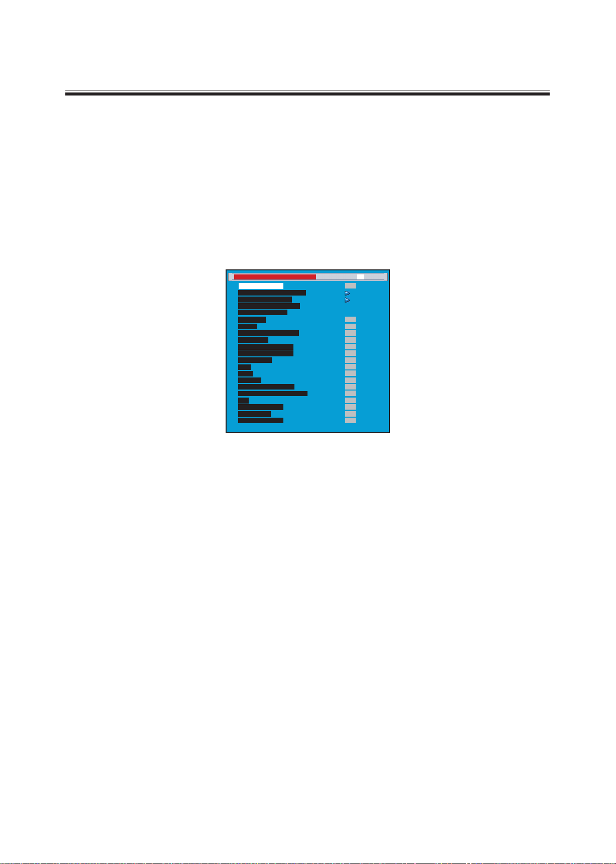
Service mode
An internal settings service menu is provided to allow adjustment of the device by qualied service personal.
Improper use of the internal settings service menu may render the device unusable. Refer to the following
sections to learn how to operate the service menu.
Starting the service mode
To start the service mode of operation and view the internal settings menu, do the following:
1.Switch on the LCD TV .
2.Press 991 on the remote control to enter the internal Service menu.
3.Press MENU to switch the service mode pages.
4.Press andto scroll through the various menu options.
5.Pressand to change the menu settings.
6.Press MENU to save the new settings and switch to next page and press EXIT to exit.
TV/AV/S-Video WHITE BALANCE, BRIGHTNESS, CONTRAST ADJUSTMENT:
--WHITE BALANCE ADJUSTMENT--
1. Press 991 on the remote control to enter the internal Service menu.
2. Press MENU to switch to the PW106 Scaler Menu page
3. Press andto scroll to Page 2-3 options
4. Press and to adjust the Offset Red, Offset Blue, Gain Red, Gain Blue menu settings.
5.Press EXIT to save the new settings and exit.
(Please don’t adjust others setting in page 2-3)
--BRIGHTNESS ADJUSTMENT—
1.Repeat the above mentioned step 1 to 2
2.Press andto scroll to PW106 FE VDC Menu Page 2-1 options
3.Pressandto adjust the Brightness setting.
4.Press andto scroll to TV/AV/S Parameter=AV1 setting and pressto run the setting. (This procedure
will copy the settings of AV1 to S & TV)
ATSC DTV WHITE BALANCE/BRIGHTNESS/CONTRAST ADJUSTMENT
1.Repeat the above mentioned step 1 to 2
2.Press andto scroll to PW106 Scaler Menu Page 2-3 options
3.Pressandto adjust the Offset Red, Offset Blue, Gain Red, Gain Blue menu settings
4.Press EXIT to save the new settings and exit.
(Please don’t adjust others settings in page 2-3)
YCbCr & YpbPr of COMPONENT 1, 2 WHITE BALANCE/BRIGHTNESS/CONTRAST ADJUSTMENT
Step 1: Getting COMPONENT 1 connect to 1080i signal. (The settings could not be saved if signals input
from
COMPONENT 2 or connect to other sources such as 720P, 480P, 480i…..,etc.)
Service Menu 40” SAM[Page 1] Nov 10 2006 TV
Panel Selection
Analog RGB Calibration
000
000
001
000
001
002
002
000
000
YCBCR Calibration
Blue Only Calibration
Reset Calibration
CUEC/ICP
Frmec
Fleshtone Correction
Film mode
3:2 film Sensitivity
2:2 film Sensitivity
Pixel Boost
DCS
000
002
000
007
004
000
000
007
DCTI
Peaking
Spatial Noise Filter
Luma Temp. Noise Filter
LAI
Dynamic Kdeint
BW Expand
Menu Shift <-->
Page 15
11
Step 2: WHITE BALANCE ADJUSTMENT OF Component—
1. Repeat the above mentioned step 1 to 2
2. Press and to scroll to PE106 FE ADC page 2-3 options
3. Pressand to adjust the Offset Red and Off Blue settings.
4. Press andto adjust the Offset Green setting.
5. Press and to adjust the Gain Green setting.
6. Pressandto scroll to 480i/480P/720P Parameter=1080i setting and press ► to run the setting. (This
procedure will copy the setting of 1080i to 480i/480P/720P)
7. Press EXIT to save the new settings and exit.
WHITE BALANCE ADJUSTMENT OF PC INPUT
1.Connecting to VGA Timing mode
2.Under service mode, Press andto scroll to PE106 FE ADC page 2-2 options
3.Pressandto adjust the Offset Red, Offset Green and Off Blue settings.
4.Pressand to adjust the Gain Red and Gain Blue settings.
5.Press EXIT to save the new settings and exit.
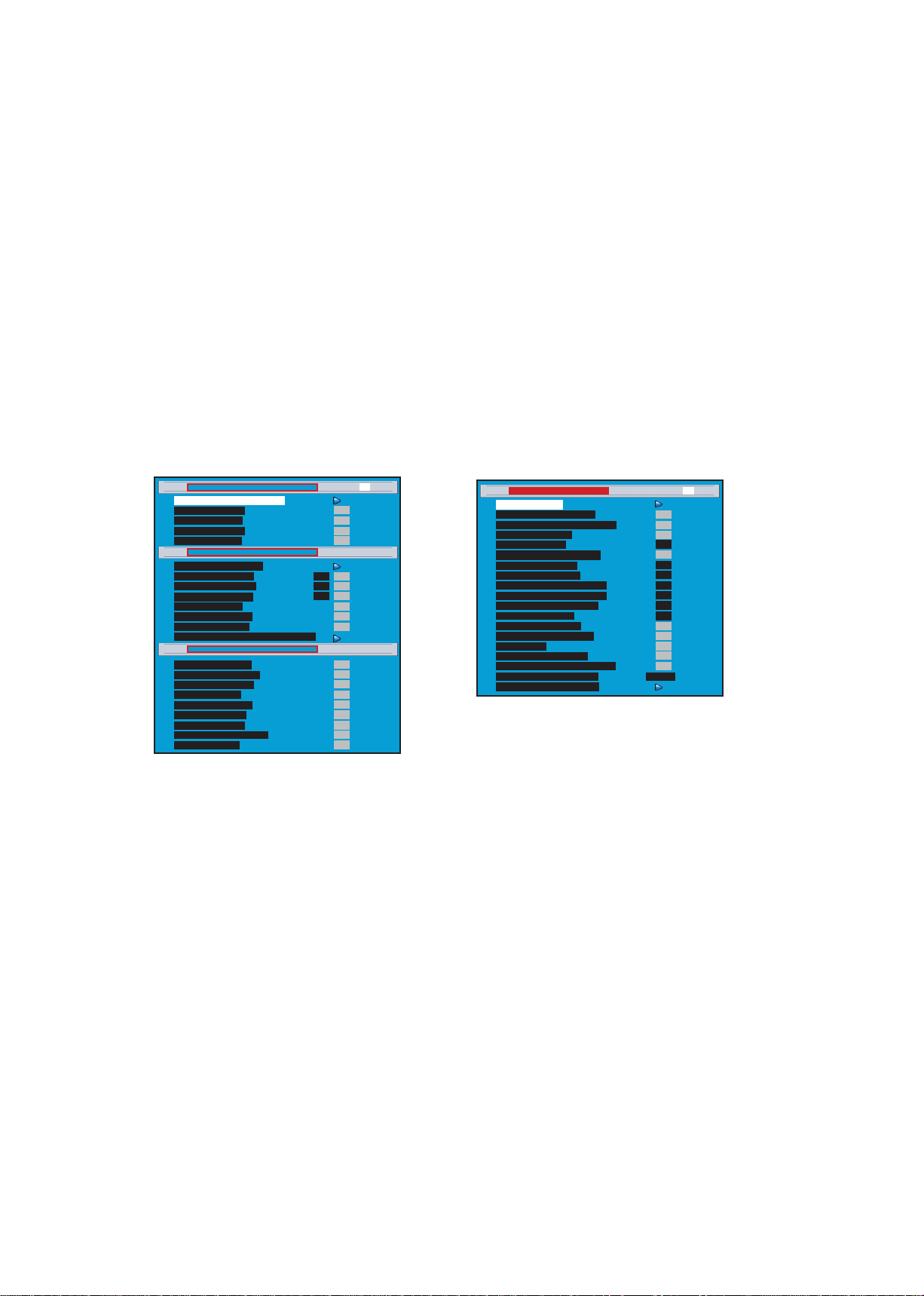
TV/AV/S Parameter = AV1
Brightness --0--
000
255
128
255
255
000
000
000
128
Contrast --128-Saturation -- 1 28 - Hue --0--
HD2 Parameter = HD1
Offset Red --127-Offset Green --127-Offset Blue --127-Gain red --127-Gain Green --127-Gain Blue --127-480i/480p/720p Parameter = 1080i
039
000
016
480
007
Menu Shift <-->
480
480
003
001
Offset Red --127-Offset Green --127-Offset Blue --127-Gain red --127-Gain Green --127-Gain Blue --127-Tint --0-Adj Scale Value 12345
PWE106FEVDC Menu [Page 2-1] TV
PWE106FEADC Menu [Page 2-2]
PWE106 Scaler Menu [Page 2-3]
000
000
000
000
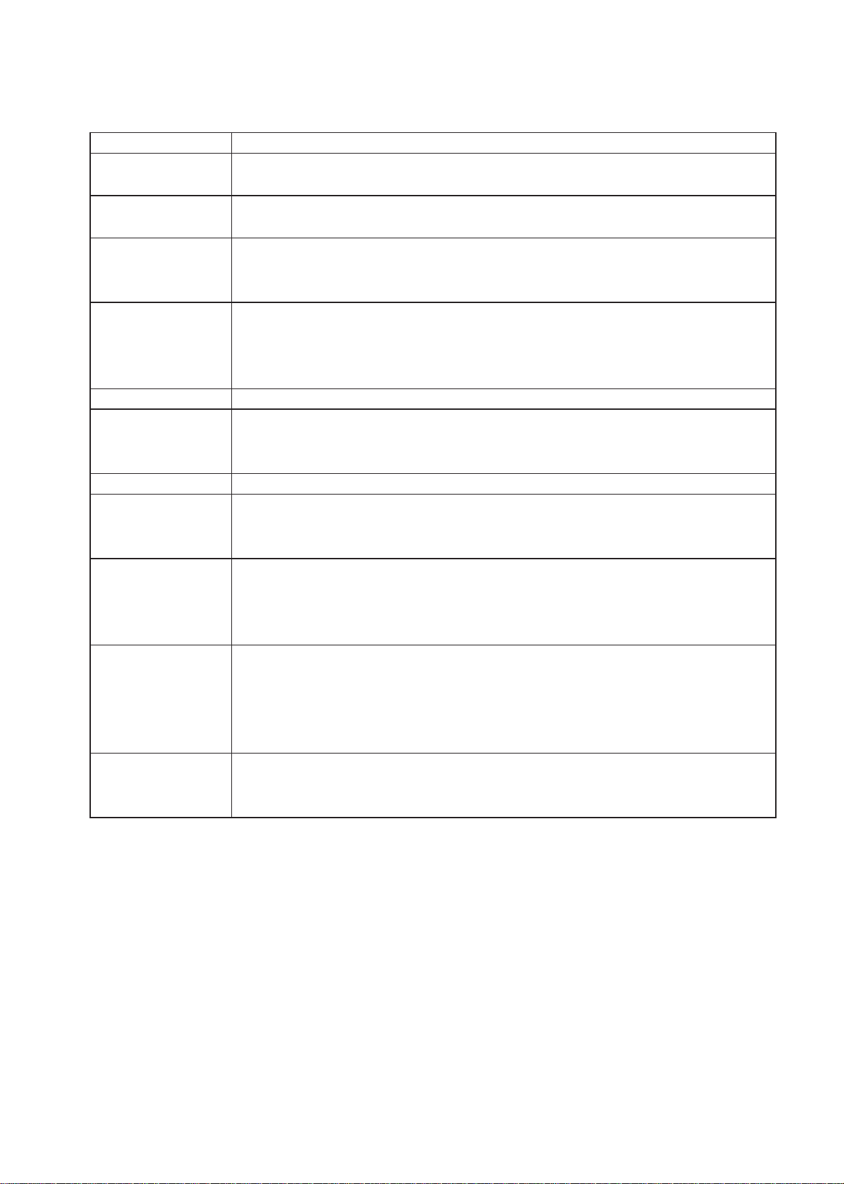
User Initialize
CH_Change_Delay --5--
010
off
020
AV1
Off
Off
Off
PC
000
Source_Change_Delay --20-Color Temp --10-Preset Channels
Patten_DSP_Delay --20-Test Pattern --Off-Source_Save --Off-Frame Lock Enable --Off-TV Video.X Audio.O --Off-Image Size Save --OFF-Ev Source Change
HP_Tolerance --20--
000
000
000
000
normal
Off
Vtotal_Tolerance --20-HD Peaking
STD Back Light --16-Back Light SEL --LG:o/A:1-Color Temp Index
Factory Reset (Adj)
OptionalMenu [Page 3] Normal TV
015
010
Page 16

12
OPERATION OF RS232 WRITING
(1)RS-232 mounted on the Main Board was the main interface writing new rmware. You can update new
rmware to U25 by RS232.
(2)Writing rmware need following equipment:
1.RS232 interface built in PC.
2.RS232 cable
3.Pixelworks Flash Upgrader software
(3)Connecting method: connecting RS232 interfaces between PC and TV set.
Firmware writing procedure:
1.Execute Pixelworks Flash Upgrader software
2.Select Baud Rate .
3.Download “appcode.crams” le.
4.Choose “Flash” mode entering standby status for writing rmware
5.Turn on TV set.
6.“Bytes Bar” will showed on the screen in few seconds indicating rmware was downloading.
7.The download process will take about 4 Minutes. It won’t change the original code when download process
intercepted. Once download process was nished system have to take at least 30 seconds updating new
rmware. Please make sure power was supplied without interruption; otherwise system will shut down.
8.System will restart automatically after nishing writing process.
Page 17

13
DDC Burning Record
1.Enter DCC Burning Program main screen .
2.Select “Working Model” and select a Model number .Connect Cable to VGA input jack .Turn
on the TV set , select then scan serial number we need. Main picture will show “PASS”
when burning OK.(Fig. 1)
3.If the main picture shows “NG”, check VGA cable connection and try again .If main picture
stay in “NG” , the TV set is a NG product. (Fig. 2)
4.Check the correction of year ,week and serial number.(Fig. 3)
(Fig. 1)
(Fig. 2)
(Fig. 3)
Page 18

14
5.Connect HDMI Cable from PC to TV set , Press computer Mouse right key and enter “SYS-
TEM Content”
6. Select “system manager “and rearrange system , screen will show “nd a new hard-
ware”. After install and screen will show Model name.
7.Revice the HDMI video and audio signal and check A/v function OK.
Page 19
15
Function Test
A. Control Bottom (control panel and remote control)
Check item Describe
POWER Press [POWER] to turn ON or OFF LCD TVPress [SLEEP] to set the off
timer from 10 to 180 min.
Remote control
effective range
The effective range is 5 meter from LCD sensor.
Indicator LED TURN ON : green light
TRUN OFF (standby mode): red lightDPMS state for PC/HDMI mode
:orange light
EARPHONE Plug in the earphone, check the speakers is mute
Plug in the earphone, check the earphone is working
Plug in the earphone, Adjust the VOLUME and make sure the volume of
earphone follow the adjusting
MENU Press [MENU] key to make sure the OSD picture will show out
CHANNEL Press [Channel] ▲ ▼ to check the channel number change normally
Press [RECALL] to check switching previously viewed channel normally
Press [NUMBER KEY] and [-/--] to enter the channel number
VOLUME Press + - to check the volume Increases or decreases
SOURCE Press [SOURCE] KEY and check each signal source is normally
Press [SOURCE] to enter TV,AV,Svideo,SCART1,SCART2,HDTV,PC,HD
MI1,HDMI2 mode
SCREEN Press [WIDE] will switches in several screen mode :FILL ALL,1 TO1,NOR
MAL,ZOOM,WIDE,ANAMORPHIC,AUTO(TV no AUTO mode)
Press [Display] will show the input signal source information.
AUDIO P r e s s [ A U D I O M OD E ] t o s w i t c h t h e a u d io m od e :
PERSONAL,STANDARD,MILD.
Press [MUTE] to disable the audio output
Press [SRS] to switch SRS WOW ON or OFF.
VIDEO P r e s s [ V I D E O M O D E ] t o s w i t c h v i d e o m o d e :
PERSONAL,STANDARD,VIVID,MILD.
Page 20

16
B. OSD (MENU)
Press [menu] to check the OSD and adjust by ▲ ▼◄ ◄KEY
Check item Describe
PICTURE Press ▲ ▼ to check the BAR slide :PRESET- BRIGHTNESS - CONTRAST-
SHARPNESS-COLOUR-TINT- COLOUR TEMP –BACKLIGHT.
Press to check the bar or number increases or decreases.PRESET :
PERSONAL,STANDARD,VIVID,MILD.
IMAGE ADJ. Press ▲ ▼ to check the BAR slide : IMAGE SIZE- FREEZE FRAME
Pressto check the setting item.IMAGE SIZE : FILL ALL,1 TO 1,NORMAL,Z
OOM,WIDE,ANAMORPHIC,AUTO(TV no auto mode)
FREEZE FRAME: ON,OFF
In PC modePress to check the bar or number increases or decreases:H POSITION,V
POSITION,
AUTO :ON,OFF
SETUP Press ▲ ▼ to check the BAR slide : LANGUAGE-SLEEP TIME-OSD SETTING-
RESET-FIRMWARE VERSION
Pressto check the setting item.LANGUAGE :
English,,Deutsch,Français,Italian
o,Español,Svenska,Suomi,Dansk,
Press ▲ ▼ to check the BAR slide OF OSD SETTING : TRANSPARENCYOSD TIMEOUT.
Press to check the red bar or number increases or decreases.SLEEP
TIMER,TRANSPARENCY,OSD TIMEOUT.
Reset all OSD setting to original setting.
AUDIO Press ▲ ▼ to check the BAR slide : VOLUME-PRESET-TREBLE-BASS-
BALANCE-SPEAKER MUTE-SRS WOW
Press to check the item correctly.
PRESET: Check the audio mode :PERSONAL,STANDARD,MILD.
Press to check the bar or number increases or decreases:VOLUM,TREBL
E,BASS,BALANCE
SPEAKER MUTE: ON,OFF
SRS WOW:ON,OFF
TUNER Press ▲ ▼ to check the BAR slide : TV TUNER SETTING-PROGRAMME
EDIT.
Press ▲ ▼ to check the BAR slide of TV TUNER SETTING : AUTO SEARCH
CHANNELS-SEARCH NEW CHANNELS-PROGRAMME TABLE-COUNTRY.
Press ▲ ▼ to check the BAR slide of TV PROGRAMME EDIT : PROGRAMMEMANUAL SEARCH-FINE TUNE-CHANNEL-AUDIO SYSTEM-EDIT LABLESAUDIO MODE-STORE PROGRAMME
Pressto check the setting .
Page 21

17
This section covers disassembly and reassembly of LCD TV. Removal of external casing, its individual parts
or internal components can render the product dangerous. There can be a risk of electric shock from exposed
components even when the device is not connected to a power source.
Disassembly
1. Unscrew and remove the pedestal completely.
2. Pull down or out the pedestal.
3. Unscrew and remove the rear cover.
4. Unscrew and remove the main board cover.
5. Unscrew and remove the power circuit board.
6. Unscrew and remove the LCD connector shield plate .
7. Unscrew and remove the VGA connector .
Assembly and disassembly procedure
Rear Cover
Pedestal
Power Main board Cover
Speaker
Power Main board Cover
37”
32”
Page 22

18
8. Unscrew and remove the AC power connector.
9. Unscrew and remove the power circuit board .
10. Unscrew and remove the main circuit board .
11. Unscrew and remove the main base plate.
12. Unscrew and remove the speakers.
13. Unscrew and remove the LED board.
14. Unscrew and lift out the LCD panel.
15. Remove the panel support screws from the LCD panel.
16. Remove the panel supports from the LCD panel carefully.
Main board
Main base plate
LED board
Page 23

19
Reassembly
Reassembly is the reverse of the disassembly procedure. When reassembling the LCD TV, note the following
points:
. The LCD panel is delicate and care should be taken to ensure that it is not scratched when removed.
Do not expose the LCD panel to dust or sharp objects.
. When xing the M-shaped bracket in place, ensure that the screw holes are correctly
lined up before attempting to install the pedestal.
. Make sure that the RC sensor cover is in place before installing the LED board.
. Make sure that the VGA connector is rmly secured before replacing the rear panel.
. Make sure that both speaker cables are connected.
. When attaching the speakers, place the main unit and the speakers face down on a soft surface. Line
up the pins on the speakers with the holes in the rear panel and secure each speaker with 2 screws.
. When connecting speaker cables, make sure that the marked speaker cable (black) isattached to the
black terminal and the unmarked cable (white) is attached to the red terminal.
Page 24

20
Exploded view:
32”
Page 25

21
Page 26

22
37”
Page 27

23
Page 28

24
Power circuit board
Printed circuit board
Bottom View
Top View
32”
37”
32”
37”
Page 29

25
Main Board
Top View
Bottom View
Page 30

26
Page 31

27
Page 32

28
Page 33

29
Trouble Shooting
No power
•Make sure the LCD is properly connected.
•Make sure the AC power cord is properly connected.
•Make sure the AC power is ON, DC power button is ON (Green LED).
•Plug another electrical device (like a radio) to the power outlet to verify that the outlet is
supplying the proper voltage.
Poor or no picture
•The TV station may be experiencing problems. Try another channel.
•The Cable TV signal may be scrambled or encoded. Please contact your local cable op-
erator.
•Make sure that connection to other components are correct.
•Make sure that setup has been done correctly after connections.
•Make sure the correct input is selected and the input signal is compatible.
Strange color, light color, or color misalignment
•Ensure that the video cable is securely connected.
•The picture may appear dim in a brightly lit room.
•Adjust brightness and contrast.
•Check the input signal setting.
No sound
•Check your audio connections
•The MUTE button may have been pressed, try pressing this button again.
•Check your audio settings, your TV audio may be set to minimum.
•Press the Volume + (Up) button on the remote control.
Remote control unit does not operate
•Make sure batteries are inserted correctly.
•Batteries could be weak or dead. Replace batteries.
•Is a uorescent light illuminated near the remote control sensor?
•The path of the remote control beam may be blocked. Make sure the path is clear and
that the remote control is aimed at the remote control sensor on the TV.
•Press only one button at a time and it is the correct one for the operation you want to perform.
Unit cannot be operated
•External inuences such as lightning or static electricity may cause improper operation. In
this case, operate the unit after rst turning on the power of the LCD and the AVC System,
or unplug the AC cord for 1 to 2 minutes, then replug again.
Power is cut off suddenly
•Is the sleep timer set?
Page 34

30
•The internal temperature of the unit has increased. Remove any objects blocking the vent
or clean as necessary.
Picture is cut off/with sidebar screen
•Is the image positioned correctly?
•Are screen mode adjustments such as picture size set correctly?
SMPS No voltage output
SMPS no Power output
Check power PIN 9~11
Voltage +5V
Press RMU or Keypad
No/OFF key check PIN 1
voltage H or L
Check power ON
Signal circuit
Check power PIN 2~4
voltage +12V
Check Main board
Regulator Circuit
Remove the power jack,check
the PIN 9~11 of SMPS still have
+5V
Check Main Bosrd Circuit
Check power PIN 2~4
Fuse or short to Ground
Check Main Board Circuit
Check SMPS
L
Yes
Yes
H
Yes
Yes
Yes
No
No
No
No
Page 35

31
Figure 2.NO Video Image
No Video image
LED light Blue
Check SMP & circuit
All of Voltage
Panem showing image
Blue,black or abnormal picture
Check PW106 Analog/
Digital Input Signal circuit
Check Main Board LVDS
Connector
Check Main board
PW106
Perpheral circuit
Check SMPS +5V & +12V &
Regulator Circuit
Check SMPS Inverter
+24V Voltage
Check main board backlight
ADJ,Inverter ON/OFF,Control signal
Check Main Board
LVDS Circuit
Check SMPS
Blue
OK
abnormal
OK
OK
Press RCU
SORCE key
Inverter or backlight
failure
Red
blue black
OK
OK
NG OK
No Audio output
Check Main Board circuit
All if Voltage
Check Audio
Processor I/O Signal circuit
Check Audio AMP I/O Signal circuit
and MUTE Control Signal
Check SMPS +12V & Regula-
tor Circuit
Check Peripheral Circuit
Check Peripheral Circuit
YES
OK
OK
NO
NO
NO
Figure 3.NO Audiio Output Sound
Page 36

32
Handing and placing Methods
1.When moving the TV set ,do not carry it by only holding the speaker
.Besure always carry the TV set by two people and holding the TV set with
two hands .One hand on up side of display and other hand on speaker.
2.Do not touch the surface of panel .Only touch the metal frame of the panel or the front cover of the TV set .
3.Place the TV set on a clean and soft foam pad.Do not place the TV set
facedown on the rough objects ,it may scratch TV panel .
Foam pad
Page 37

GND K(5)
A_|VS1
A_|CD1
A_MDO(3)
1
R197
10K
+3V3_STV
353637383940414243444546474849505152535455565758596061626364656667
73
74
J10
123456789
ICME68H-D1121_NC
2
PCMCIA_D(3)
PCMCIA_D(4)
K(7)
A_MICLK
JTAG_TRST K(1,6)
JTAG_TCK K(1,6)
JTAG_TMS K(1,6)
3
R504-NC0
R5050
R503-NC0
R502-NC0
U18
STV0700_NC
JTAG_TMS K(1,6)
R501-NC
8
11
10
65
109
0
0
R500
+3V3_STV
R151
R152
4
I2C_LOCAL_SCLK(2,6,7)
I2C_LOCAL_SDAK(2,6,7)
TDA_VALIDK(6)
TDA_CLKK(6)
5
TDA_SYNC
K(6)
R153 47R
110
MCLKA
GND_DVB1
NC2
NC1
VCC_DVB2
VCC_DVB1
SA032SA133SCL31SDA30MCLK50MISTRT49MIVAL48MDI040MDI141MDI242MDI343MDI444MDI545MDI646MDI747MOCLK63MOSTRT62MOVAL61MOD053MOD154MOD255MOD356MOD457MOD558MOD659MOD7
100R
100R
TDA_DAT(0)
TDA_DAT(1)K(6)
TDA_DAT(2)K(6)
TDA_DAT(3)K(6)
TDA_DAT(4)K(6)
TDA_DAT(7)K(6)
TDA_DAT(5)K(6)
TDA_DAT(6)K(6)
K(6)
PCMCIA_|IOWR
A_MDO(4)
A_MDO(5)
A_MDO(6)
A_MDO(7)
A_|CE2
PCMCIA_|IORD
A_MISTRT
A_MDI(0)
A_MDI(1)
A_MDI(2)
A_MDI(3)
PCMCIA_AVCC
PCMCIA_VPP
A_MDI(4)
A_MDI(5)
10111213141516171819202122232425262728293031323334
PCMCIA_D(5)
PCMCIA_D(6)
PCMCIA_D(7)
A_|CE1
PCMCIA_A(10)
PCMCIA_|OE
PCMCIA_A(11)
PCMCIA_A(9)
PCMCIA_A(8)
PCMCIA_A(13)
PCMCIA_A(14)
PCMCIA_|WE
A_|RDY|IRQ
PCMCIA_AVCC
PCMCIA_VPP
A_MIVAL
A_MICLK
K(7)
A_MIVAL K(7)
A_MDI(0)
A_MISTRT
R155 47R
R154 47R
R156 47R
92
105
MDIA094MDIA196MDIA299MDIA3
MIVALA
MISTRTA
RA2
F8P4R-0
18
27
36
45
RA1
F8P4R-0
18
27
36
45
A_MDI(1)
R157 47R
R230
R228
K(7)
K(7)
A_MOSTRT
A_MDI(2)
R158 47R
A_MOVALK(7)
A_MDI(3)
A_MDI(4)
A_MDI(5)
A_MDI(6)
A_MDI(7)
A_MDO(0)
A_MDO(1)
A_MDO(2)
A_MDO(3)
A_MOCLK
R159 47R
R161 47R
R160 47R
R162 47R
103
107
112
114
MDIA4
MDIA5
R163 47R
116
MDIA6
R165 47R
118
MDIA7
R167 47R
127
MOCLKA
R177 47R
R173 47R
R169 47R
R175 47R
R171 47R
125
MODA01MODA13MODA25MODA374MODA476MODA578MODA680MODA7
MOVALA
MOSTRTA
0R
0R
R229
0R
R164 33R
R174 33R
R166 33R
R176 33R
R168 33R
R170 33R
R172 33R
A_MDI(6)
A_MDI(7)
A_RESET
A_|WAIT
A_|INPACK
PCMCIA_|REG
A_MOVAL
A_MOSTRT
A_MDO(0)
A_MDO(1)
A_MDO(2)
A_MOCLK
A_|CD2
R199
10K
R198
10K
1
DTV MODULE-CI(option)
+3V3_STV
+3V3_STV
68
71
72
K(7)
K(7)
|DATOE
DATDIR
PCMCIA_D(5) K(2,7)
PCMCIA_D(1) K(2,7)
PCMCIA_D(4) K(2,7)
PCMCIA_D(3) K(2,7)
PCMCIA_D(2) K(2,7)
PCMCIA_D(0) K(2,7)
PCMCIA_D(6) K(2,7)
PCMCIA_D(7) K(2,7)
+3V3_BUF
C136
C135
R210 33R
R211 33R
R207 33R
R204 33R
R208 33R
R206 33R
R209 33R
C133
100n
A02A13A24A35A46A57A68A7
VCC
20
+3V3_BUF
B018B117B216B315B414B513B612B7
U22
100n
R212 33R
R213 33R
R214 33R
9
19
1
G
DIR
GND
FB34
10
11
10u
2
PBY32_19 OHM
+3V3
74LVC245A_NC
MIU_DATA(7)K(2,7)
MIU_DATA(6)K(2,7)
MIU_DATA(5)K(2,7)
MIU_DATA(4)K(2,7)
MIU_DATA(3)K(2,7)
MIU_DATA(2)K(2,7)
MIU_DATA(1)K(2,7)
MIU_DATA(0)K(2,7)
PCMCIA_A(5)
PCMCIA_A(4)
PCMCIA_A(3)
PCMCIA_A(2)
PCMCIA_A(1)
PCMCIA_A(0)
12
VCC
GND
10
1
C134
+3V3_BUF
100n
20
U23
PCMCIA_A(8)
PCMCIA_A(9)
PCMCIA_A(10)
PCMCIA_A(12)
PCMCIA_A(11)
PCMCIA_A(14)
PCMCIA_A(13)
12
Q019Q118Q217Q316Q415Q514Q613Q7
VCC
D02D13D24D35D46D57D68D79LE11OE
3
GND
10
1
74LVC573ADB_NC
R205 33R
R203 33R
MIU_ADDR(0)
MIU_ADDR(6)
MIU_ADDR(5)
MIU_ADDR(4)
MIU_ADDR(3)
MIU_ADDR(2)
MIU_ADDR(1)
|ADOE
ADLE
ADLEK(7)
|ADOE
K(7)
MIU_ADDR(9)
MIU_ADDR(10)
MIU_ADDR(12)
MIU_ADDR(11)
MIU_ADDR(14)
MIU_ADDR(13)
MIU_ADDR(8)
4
5
K(7)
A_RESET
A_RESET
120
RSTA
119
RSTB
A_|WAIT K(7)
A_|WAIT
122
FB30
121
WAITA
PBY32_19 OHM
PCMCIA_|REG K(7)
PCMCIA_|REG
123
WAITB
PCMCIA_VPPPCMCIA_5V
C124
100n
C123
100n
K(7)
K(7)
A_|CE2
A_|CE1 K(7)
PCMCIA_|WE
PCMCIA_|IOWRK(7)
PCMCIA_|OE K(7)
PCMCIA_|IORD K(7)
A_|CE1
A_|CE2
PCMCIA_|OE
PCMCIA_|WE
PCMCIA_|IORD
PCMCIA_|IOWR
90
89
97
88
OE
WE
REG
IORD
CE1A82CE1B81CE2A87CE2B
IOW_R
C125
100n
FB31
PBY32_19 OHM
PCMCIA_5V PCMCIA_AVCC
K(7)
K(7)
K(7)
ADLE K(7)
|ADOEK(7)
VCCEN
DATDIR
|DATOE
|ADOE
DATDIR
|DATOE
ADLE
VCCEN
PCMCIA_A(7)
PCMCIA_A(6)
C130
+3V3_BUF
100n
20
U21
74LVC573ADB_NC
Q019Q118Q217Q316Q415Q514Q613Q7
D02D13D24D35D46D57D68D79LE11OE
67
70
69
85
66
68
GND-DVB2
ADLE
DATOE
VCCEN
ADOE
DATDIR
86
GND-PROC
9
GND-TSO
52
GND-TSI
39
GND-CORE
37
VCC-PROC
38
VCC-TSO
64
VCC-TSI
51
VCC-CORE
36
R510
4K7
R196
10K
+3V3_STV
PCMCIA_D(0)
PCMCIA_D(1)
PCMCIA_A(4)
108
MOCLKB
PCMCIA_A(3)
PCMCIA_A(2)
+3V3_STV
104
91
MOVALB
MOSTRTB
PCMCIA_D(2)
PCMCIA_A(1)
PCMCIA_A(0)
PCMCIA_5V
102
106
MODB093MODB195MODB298MODB3
A_|IOIS16
111
MODB4
MODB5
R195
R194
R193
R192
R191
R190
R189
R188
113
10k
10k
10k
10k
10k
10k
10k
10k
115
MODB6
MODB7
K(7)
K(7)
A_|CD2
A_|CD1
A_|CD1
A_|CD2
6
CD1A72CD2A7CD1B71CD2B
A_|RDY|IRQ K (7)
A_|RDY|IRQ
101
100
RDY|IRQA
RDY|IRQB
PCMCIA_A(12)
PCMCIA_A(7)
PCMCIA_A(6)
PCMCIA_A(5)
A_MDO(4)
A_MDO(5)
A_MDO(6)
A_MDO(7)
R185 47R
R181 47R
R179 47R
R183 47R
84
CLK35RESET34EXTINT12INT14RD|DIR17WR|STR16CS18WAIT|ACK15A1519A1620A1721A1822A1923A2024A2125A2226A2327A2428A2529EXTCS
60
3
3
OUT
VDD
4
+3V3
GND2VDD1
1
C121
10K
R186
+3V3_STV
+3V3_STV
R184 33R
R178 33R
R180 33R
R182 33R
R201 10K
U19
FXO-31FL_NC
+3V3_STV
RESET_STV
MIU_WENK(2,7)
MIU_OENK(2,7)
STV_CSK(1)
MIU_RDYK(2,7)
MIU_ADDR(15)K(2,7)
MIU_ADDR(16)K(2,7)
MIU_ADDR(17)K(2,7)
MIU_ADDR(18)K(2,7)
STV_INTK(1)
1n0
PCMCIA_5V
RESET_STVK(1)
R187
10K
5
7
6
8
SET
OUT1
OUT2
FAULT_
IN11IN2
ON_
U20
+5V
GND
2
3
4
VCCEN
R200
10K
MIU_ADDR(19)K(2,7)
C122
10u
R202
2K0
ST890C_NC
13
+3V3_STV
+3V3_CORE
+3V3_STV
C129
100n
MIU_ADDR(20)K(2,7)
MIU_ADDR(21)K(2,7)
MIU_ADDR(22)K(2,7)
MIU_ADDR(23)K(2,7)
MIU_ADDR(24)K(2,7)
STV_A25K(1)
C128
100n
C127
100n
C126
10u
FB32
PBY32_19 OHM
FB33
PBY32_19 OHM
+3V3
MIU_ADDR(7)
+3V3_CORE
C132
100n
C131
10u
+3V3
VCCEN
TS_SYNCK(7)
TS_VALIDK(7)
TS_DATA(0)K(7)
TS_DATA(1)K(7)
TS_DATA(2)K(7)
TS_DATA(3)K(7)
TS_DATA(4)K(7)
TS_DATA(5)K(7)
TS_DATA(6)K(7)
TS_CLKK(7)
D D
TS_DATA(7)K(7)
C C
B B
A A
Page 38

GND K(5)
1
DTV MODULE-MK3 TUNER+COFDM
7
15
24
29
40
45
52
56
58
63
TDA10046AHT
2
R142 33R
R141 100R
TDA_SYNC K(7)
TDA_DAT(7) K(7)
TDA_DAT(6) K(7)
TDA_CLK K(7)
TDA_VALID K(7)
R147 33R
R149 33R
R143 33R
R145 33R
49
37
35
51
33
36
DEN
OCLK
R144 100R
R146 100R
R148 100R
PSYNC
UNCOR
12
SACLK
VSS1
VSS2
VSS3
VSS4
VSS5
VSS6
VSS7
VSSA_OSC
VSS_PLL_ADC
VSSA_ADC
C113
100n
FB28
PBY32_19 OHM
1
+1V8FE +1V8FE
2
FB27
C108
47u16V
PBY32_19 OHM
C107
C101
100n
C100
100n
100n
C99
+3V3FE
+3V3FE
C106
C105
C104
C103
C102
100n
100n
100n
100n
100n
100n
+3V3 +3V3FE
C112
47u16V
+3V3FE
C111
100n
C110
100n
C109
100n
19
34
47
5
22
42
50
53
57
59
60
64
18
32
14
TRST
13
ENSERI
31
S_DO
COFDM CHANNEL DECODER
S_OCLK
17
20
16
TDI
TCK
TMS
TDO
VDDE33_1
VDDE33_2
VDDE33_3
VDDI18_1
VDDI18_2
VDDI18_3
VDDI18_4
VDDA18_OSC
VDDA18_PLL
VDD18_PLL_ADC
VDDA33_ADC
VDD33_ADC
CLR_9AGC_TUN1AGC_IF2VIP62VIM61XIN54XOUT55GPIO021GPIO123GPIO225GPIO326SADDR011SDDR110SDA8SCL6SDA_TUN4SCL_TUN3TEST
U17
R121 10K
4MHz_PNX K(1)
C116
100n
RESET_FE_nK(1)
30
S_DEN
28
S_PSYNC
27
S_UNCOR
R132 10K
R131 33R
TDA_DAT(0) K(7)
TDA_DAT(1) K(7)
TDA_DAT(3) K(7)
TDA_DAT(2) K(7)
TDA_DAT(4) K(7)
R134 33R
R137 33R
R133 33R
R135 33R
R136 33R
38
DO0
DO139DO241DO343DO444DO546DO648DO7
TDA_DAT(5) K(7)
R140 33R
R118
R113
390R
3
INVERTER
4
TUNER MK3
U14
MT15MT
R111 330R
4
U15
74AHC1GU04GW
4
GND
VCC
3
5
+3V3
14
NC
2
1
2
R112
680K
IF-2
11
IF-1
10
IF-AGC
9
IF-OUT
8
XTAL
6
SDA
5
SCL
4
PLL
3
VTUN
7
AGC
2
U16
74AHC1GU04GW
5
+3V3
INVERTER
R114 220K
330R
R115 330R
4
4
GND
VCC
3
NC
2
2
R119 220K
1
R117
680K
R116
100R
R123
+5Vclean+5Vclean
R122
R120
100R
C115
1n5
C145
470P
C144
220P
C114
47u/16V
C118 100n
C117 100n
4K7
4K7
R125 100K
22pF
C142
Y2
C120
R126 1K0
+5Vclean
100n
C119
100n
R129
R128
R127
4K7
4MHz
100K
100K
+3V3FE
FE_LOCKK(1)
C143 22pF
R130
4K7
I2C_LOCAL_SDAK(1,2,7)
I2C_LOCAL_SCLK(1,2,7)
R139
2K7
R138
+5V +5V
2K7
3
4
DC
5
D D
1
MT
MT
13
12
2.2UH
FB29
+5Vclean
C C
B B
I2C_TDA_SCL
I2C_TDA_SDA
A A
5
Page 39

CVBS_VCR
C137
SDA
SCL
101
Analog Backend
1
IRQ
BLUE/U
GREEN/Y
RED/V
1
+12V K(3)
+5V
75R
GND K(5)
J9
12345
GREEN/Y
BLUE/U
2
B4B-EH-A
VIDEO IBO LINK
RED/V
75R
R514
C98
22p
C97
75R
R513
22p
C96
22p
3
L4 SBK16-102
L5 SBK16-102
L6 SBK16-102
L2 SBK16-102
L1
PBY32-190
L3 SBK16-102
19171513119753
DVBT
22P8562-20R10-01G
2018161412
2
123
SDA
R99 100R
J7
4
CONTROL IBO LINK
C74
100p
C73
100p
SCL
C72
22p
IRQ
R101 100R
R102 75R
B4B-EH-A
+5VK(2)
3
B4B-EH-A-K
R226 0
864
10
L7 SBK16-102
L10 SBK16-102
R227 0
L1
L1
CVBS_VCR
R104 75R
FB19 PBY32_19 OHM
L9 SBK16-102C81
L8 SBK16-102
1
+5V
2
R1
J8
12345
AUDIO IBO LINK
C82
22p
22p
R1
C80
22p
R512
R105 75R
I2C_TV_SCLK(1)
I2C_TV_SDAK(1)
TV_IRQK(1)
C79
R106 1K5
1u
C83
4n7C84 22p
FB20 PBY32_19 OHM
C87 22p
C86
390p
75R
R506
C85
390p
R107
75R
Y_CVBSK1
C75
1u
C76
4
+3V3
+3V3
UDA1334BTS
7
U13
C70 100n
FB18
PBY32_19 OHM
2R2
C71 100n
R98 2R2
R100
+3V3clean
5
11
VDDD
4
13
BCK1WS
2
VDDA
DATAI
3
SFOR1
SFOR0
SYSCLK
6
MUTE8DEEM
9
4n7
R103 1K5
C78
VREF-DAC
VSSD
VSSA
47u16V
C77
100n
12
5
15
16
VOR
VOL14PCS
10
C89
390p
75R
R507
C88
FB21 PBY32_19 OHM FB22 PBY32_19 OHM
390p
R108
75R
G/YK1
C90 22p
C92
390p
75R
R508
C91
FB23 PBY32_19 OHM FB24 PBY32_19 OHM
390p
R109
75R
B/CbK1
FB26 PBY32_19 OHM
C95
390p
75R
R509
C93 22p
C94
FB25 PBY32_19 OHM
390p
R110
75R
R/CrK1
4
5
PNX_I2S_OUT_SCKK(1)
PNX_I2S_OUT_WSK(1)
PNX_I2S_OUT_SDK(1)
FSCLKK(1)
D D
C C
B B
A A
Page 40

CN4
OC-0805X002
3 2
+3V3
1
DIGITAL OUTPUT
1
C67
100n_NC
GND K(5)
+5V
1
+5V
D4_NC
0
EZJZ1V800AA
FB17
R94
470RU_NC
DTV MODULE-interface
C66
1K
1K0
Q5
R91
3904
0 R
470R
2
R93
180R
R92
1K0
3
RXD0 K(1)
TXD0 K(1)
2
+3V3
R89
3
R90
C69
330p
C65 100n
C68
330p
SPDIFK(1)
4
R97 100R
R95 100R
R216
0R
4
R96 0
+5V
R215
123
4
5
J6
S3B-PH-K
UART CON
FOR
COMPAIR ONLY
0R
CN7
234
PHONEJACK STEREO
1
5
5
D D
C C
B B
A A
Page 41

GND K(5)
+5V
+5V
1
R65
+3V3
+3V3clean
6/6
100K
+1V8FE
+1V2_PNX
+5V
+5Vclean
1
DTV MODULE-pow er supply
C43 100u
R64 33R
Q6
3906
23
+12V
+12V
2
1
R62
1K0
R63 100K
Q3
TL431CZ(UTC)
R67 47KR66 1K0
C37 RES
21
C139 220u/16V
FB11 10u
FB35 3.3u COIL
C40
100n
Q4
IRLML2502
R68
180R
FB8 47u
D1
B340
C39 470p
3
1
2
SWE
SWC
TIMC
U7
C41
470n
4
FB
2
LD1117V18
3
C46
100u
C47
4
O
OUT
COM
1
IN
C53
470u 16V
21
B340
1m0 16V
D2
FB14 10u
C52
FB13
220u
C49
470n
C48 470p
4
3
1
2
FB
SWE
SWC
TIMC
470u 16V
U10
21
D3
C54 470p
3
1
2
SWE
SWC
TIMC
APL1117-5
B340
100u
C58
4
2
O
OUT
COM
1
IN
3
<>
FB16
100u
C55
470n
4
U12
C57
100n
FB
APL1117-5
C61
470u 16V
100u
C64
4
2
O
OUT
COM
1
IN
3
C63
100n
2
CIN_NEG
5
C56
U11
330u
NCP303LSN30
C59 4n7
R88 100R
R86 3K9
R87 820R
C60
4n7
RESET_n K (1,2)
1
OUTP
INP
2
修正
GND
3
NC
4
0904
CD
5
1
2
J4
SKQTLB
4
3
3
4
C44 4n7
R73 1K8
CIN_NEG
DCOL
U6
MC34063AP1
3
4
8
+12V
VCC
5
6IS7
R72
1R0
R71
1R0
R70
1R0
330u
C42
R69
1R0
+12V
K(1,2)
R75 100R
R74 1K0
C45
4n7
U8
MC34063AP1
DCOL
8
CIN_NEG
VCC
5
6IS7
R79
1R2
R78
1R0_NC
R77
1R0_NC
330u
C50
R76
1R0_NC
R80 100K
C51
4n7
U9
MC34063AP1
DCOL
8
VCC
6IS7
R84
1R0
R83
1R0
R82
1R0
R81
1R0
R85 1K0
POWER ON RESET
C62
33n
5
+3V3
D D
C C
B B
A A
5
Page 42

+5V
+5V
1
GND K(5)
1
DTV MODULE-menory
+3V3_NOR48
MIU_DATA(0) K(1,7)
MIU_DATA(1) K(1,7)
MIU_DATA(2) K(1,7)
MIU_DATA(3) K(1,7)
MIU_DATA(4) K(1,7)
MIU_DATA(5) K(1,7)
MIU_DATA(6) K(1,7)
MIU_DATA(7) K(1,7)
MIU_DATA(8) K(1,7)
MIU_DATA(9) K(1,7)
MIU_DATA(10) K(1,7)
MIU_DATA(11) K(1,7)
MIU_DATA(12) K(1,7)
MIU_DATA(13) K(1,7)
MIU_DATA(14) K(1,7)
MIU_DATA(15) K(1,7)
R56 10K
U2
29
2
C27
100n
+3V3_NOR48+3V3
FB5
100MHz
3
37
C26
10u
DV0
DV131DV233DV335DV438DV540DV642DV830DV9
VDD
A025A124A223A322A421A520A619A718A88A97A106A115A124A133A142A151A1648A1717A1816A199A2010RB15RP12WE11OE28CE26BYTE
MIU_ADDR(1)K(1,7)
MIU_ADDR(2)K(1,7)
MIU_ADDR(3)K(1,7)
MIU_ADDR(4)K(1,7)
32
44
DV7
45
DV1034DV1136DV1239DV1341DV1443DV15
A-1
EPROM 4Mx8 /2MX16
MIU_ADDR(5)K(1,7)
MIU_ADDR(6)K(1,7)
MIU_ADDR(7)K(1,7)
MIU_ADDR(8)K(1,7)
MIU_ADDR(9)K(1,7)
MIU_ADDR(10)K(1,7)
MIU_ADDR(11)K(1,7)
MIU_ADDR(12)K(1,7)
MIU_ADDR(13)K(1,7)
MIU_ADDR(14)K(1,7)
MIU_ADDR(15)K(1,7)
MIU_ADDR(16)K(1,7)
MIU_ADDR(17)K(1,7)
MIU_ADDR(18)K(1,7)
MIU_ADDR(19)K(1,7)
14
13
NC
VPP/WP
46
46
27
27
47
+5V +5V
R55 470R
MIU_ADDR(20)K(1,7)
MIU_ADDR(21)K(1,7)
+5V
MIU_WENK(1,7)
NOR_RYBYK(1)
RESET_nK(1,3)
MIU_OENK(1,7)
NOR_CSK(1,7)
+3V3_NOR48
+3V3_NOR48
R59
R58
R57
user_EEPROM_WP K(1)
I2C_LOCAL_SCL K(1,6,7)
user_EEPROM_WP
I2C_LOCAL_SCL
I2C_LOCAL_SDA
3K3
3K3
R250
0
10K
I2C_LOCAL_SDA K(1,6,7)
R61
100R
R60
100R
WC_
SCL
SDA
6
6
5
5
7
7
WC
WC
SCL
SCL
SDA
SDA
2
3
U4
8
8
M24C64-WMN6
8
8
SDRAM_ADDR(12) K(1)
SDRAM_DATA(0) K(1)
SDRAM_DATA(1) K(1)
SDRAM_DATA(2) K(1)
SDRAM_DATA(3) K(1)
SDRAM_DATA(4) K(1)
SDRAM_DATA(5) K(1)
SDRAM_DATA(6) K(1)
SDRAM_DATA(7) K(1)
SDRAM_DATA(8) K(1)
SDRAM_DATA(9) K(1)
SDRAM_DATA(10) K(1)
SDRAM_DATA(11) K(1)
SDRAM_DATA(12) K(1)
SDRAM_DATA(13) K(1)
SDRAM_DATA(14) K(1)
SDRAM_DATA(15) K(1)
SDRAM_DQM0 K(1)
SDRAM_DQM1 K(1)
C35
10u
36
40
VDDQ
D02D14D25D37D48D510D611D713D842D9
NC
C31
100n
C34
100n
C30
100n
C33
4
100n
C29
100n
C32
100n
C28
100n
NC
49
VDDQ
43
VDDQ
9
VDDQ
3
VDD
27
VDD
14
VDD
1
A2
A023A3
A1
25
24
A530A6
A4
31
26
29
A934A732A833A1022A11
35
44
D1045D1147D1248D1350D1451D15
SYNC DRAM 4X2MX16
BA020BA1
21
39
53
15
DQML
CLK38CKE37CS19RAS18CAS17WE
16
VSSQ
DQMU
VSSQ
VSSQ
VSSQ
VSS
VSS
VSS
6
U3
52
46
12
54
41
28
FB7
100MHz
+5V
C36 100n
VSS
VSS
4
4
E0
E23E1
E0
E23E1
1
2
1
2
+5V
4
FB6
100MHz
+3V3
SDRAM_ADDR(0)K(1)
SDRAM_ADDR(1)K(1)
SDRAM_ADDR(2)K(1)
SDRAM_ADDR(3)K(1)
SDRAM_ADDR(4)K(1)
SDRAM_ADDR(5)K(1)
SDRAM_ADDR(6)K(1)
SDRAM_ADDR(7)K(1)
SDRAM_ADDR(8)K(1)
SDRAM_ADDR(9)K(1)
SDRAM_ADDR(10)K(1)
SDRAM_ADDR(11)K(1)
SDRAM_ADDR(13)K(1)
SDRAM_ADDR(14)K(1)
SDRAM_CLKK(1)
SDRAM_CKEK(1)
SDRAM_RASK(1)
SDRAM_CASK(1)
SDRAM_WEK(1)
5
D D
C C
B B
A A
5
Page 43

GND K(5)
DTV MODUL E- P N X831x
1
R15
10K
SDRAM_CAS K(2)
SDRAM_RAS K(2)
SDRAM_ADDR(1) K(2)
SDRAM_ADDR(2) K(2)
SDRAM_ADDR(3) K(2)
SDRAM_ADDR(4) K(2)
SDRAM_ADDR(5) K(2)
SDRAM_ADDR(6) K(2)
SDRAM_ADDR(7) K(2)
SDRAM_ADDR(8) K(2)
SDRAM_ADDR(9) K(2)
SDRAM_ADDR(10) K(2)
SDRAM_ADDR(11) K(2)
SDRAM_ADDR(12) K(2)
SDRAM_ADDR(13) K(2)
SDRAM_ADDR(14) K(2)
SDRAM_DQM0 K(2)
143
142
150
151
SDRAM_ADDR10
SDRAM_ADDR11
SDRAM_ADDR12
SDRAM_ADDR13
SDRAM_ADDR14
SDRAM_DATA10
SDRAM_DATA11
SDRAM_DATA12
SDRAM_DATA13
SDRAM_DATA14
SDRAM_DATA15
127
126
125
124
123
138
DQM0
SDRAM_DQM1 K(2)
133
DQM1
SDRAM_ADDR(0) K(2)
156
149
148
147
146
SDRAM_ADDR2
SDRAM_ADDR3
SDRAM_ADDR4
SDRAM_ADDR5
SDRAM_ADDR6
SDRAM_DATA2
SDRAM_DATA3
SDRAM_DATA4
SDRAM_DATA5
SDRAM_DATA6
116
117
118
121
122
152
145
144
SDRAM_ADDR7
SDRAM_ADDR8
SDRAM_ADDR9
SDRAM_DATA7
SDRAM_DATA8
SDRAM_DATA9
132
129
128
153
154
155
SDRAM_ADDR0
SDRAM_ADDR1
2
(SDRAM)
U1-4
SDRAM_DATA0
SDRAM_DATA1
113
114
115
SDRAM_CKE K(2)
SDRAM_WE K(2)
SDRAM_CLK K(2)
141
137
140
136
139
WE
VAS
RAS
CKE
HSCKB
NC
17
DTR0
VCXO_CLOCK
(GPIO)
U1-7
PNX831x
IR_IN31IR_OUT32PWM
SW DEBUGGING ONLY
J2
B2B-PH-K
1
2
+3V3
UART1_TX
UART1_RX
R17 10K
R16 10K
18
19
176
177
TX1
RX1
ITU_OUT0
ITU_OUT1
VS
VPP33C434C835SC1_DA45SC1_CMDVCC46SC1_RST47SC1_OFF48SC1_CCK49CTS012RTS013RX014TX015DCD0
+3V3
R18 10K
178
ITU_OUT2
R19 10K
179
ITU_OUT3
180
181
ITU_OUT4
TV_IRQ K(5)
R22
182
ITU_OUT5
ITU_OUT6
+3V3
10K
183
ITU_OUT7
185
+3V3
10K
R23
184
ITU_CLOCK
NC
MIU_ADDR(14) K(2,7)
MIU_ADDR(15) K(2,7)
MIU_ADDR(0) K(2,7)
MIU_ADDR(1) K(2,7)
MIU_ADDR(2) K(2,7)
MIU_ADDR(3) K(2,7)
MIU_ADDR(4) K(2,7)
MIU_ADDR(5) K(2,7)
MIU_ADDR(6) K(2,7)
MIU_ADDR(7) K(2,7)
MIU_ADDR(8) K(2,7)
R24
10K
MIU_ADDR075MIU_ADDR180MIU_ADDR281MIU_ADDR382MIU_ADDR483MIU_ADDR584MIU_ADDR685MIU_ADDR786MIU_ADDR887MIU_ADDR9
(MIU)
PNX831x
U1-5
PLL_OUTX0
16
NC
MIU_DATA069MIU_DATA167MIU_DATA265MIU_DATA363MIU_DATA459MIU_DATA557MIU_DATA655MIU_DATA753MIU_DATA868MIU_DATA966MIU_DATA1064MIU_DATA1162MIU_DATA1258MIU_DATA1356MIU_DATA1454MIU_DATA15
MIU_ADDR(16) K(2,7)
MIU_ADDR(17) K(2,7)
MIU_ADDR(18) K(2,7)
MIU_ADDR(9) K(2,7)
MIU_ADDR(10) K(2,7)
MIU_ADDR(11) K(2,7)
88
MIU_ADDR(19) K(2,7)
MIU_ADDR(12) K(2,7)
MIU_ADDR(13) K(2,7)
100
MIU_ADDR1089MIU_ADDR1190MIU_ADDR1291MIU_ADDR1392MIU_ADDR1493MIU_ADDR1596MIU_ADDR1697MIU_ADDR1798MIU_ADDR1899MIU_ADDR19
MIU_RDY
MIU_CS_N074MIU_CS_N173MIU_CS_N272MIU_CS_N371MIU_OE_N70MIU_WEN
52
109
MIU_ADDR(20) K(2,7)
MIU_ADDR(21) K(2,7)
MIU_ADDR(22) K(2,7)
MIU_ADDR(23) K(2,7)
101
102
103
104
MIU_ADDR20
MIU_ADDR21
MIU_ADDR22
MIU_ADDR(24) K(2,7)
110
107
105
MIU_MASK1
MIU_ADDR23
MIU_ADDR24
50
MIU_LBA
108
51
MIU_BAA
106
MIU_CLK
PNX831x
MIU_MASK0
1
2
R31 33R
R29 33R
R32 33R
R33 33R
R34 33R
SDRAM_DATA(0)K(2)
SDRAM_DATA(1)K(2)
SDRAM_DATA(2)K(2)
SDRAM_DATA(3)K(2)
SDRAM_DATA(4)K(2)
SDRAM_DATA(5)K(2)
SDRAM_DATA(6)K(2)
SDRAM_DATA(7)K(2)
SDRAM_DATA(8)K(2)
SDRAM_DATA(9)K(2)
SDRAM_DATA(10)K(2)
SDRAM_DATA(11)K(2)
SDRAM_DATA(12)K(2)
SDRAM_DATA(13)K(2)
SDRAM_DATA(14)K(2)
SDRAM_DATA(15)K(2)
3
R10
+3V3_PNX
+3V3
+3V3
R9
10K
R7
R6
68R/NC
C1
100p/NC
PNX_TMS
10K
U1-8
R11
RESET_nK(2,3)
PNX_TCK
10K/NC
R5
R8
10K
J1
FTSH
19 20
17 18
15 16
33
R4
13 14
11 12
9 10
7 8
5 6
3 4
1 2
10K
+3V3
4
R1
10K
R2
PNX_TDI
PNX_TDO
R3
10K
+3V3
+3V3
PNX_TRST
5
5
6
445
6
7
7
8
8
9
9
11223
3
10K
(JTAG-ETAG-SYS)
YDI
208
33R
PNX_TDI
RESET_FE_nK(6)
R13 33R
R12 33R
5
194
189
PCST00
PCST01
SYS_RESETN
TDO
DSU_TPC0
207
PNX_TDO
5
6
445
7
8
9
11223
3
5
6
445
7
8
9
11223
3
5
6
445
7
8
9
11223
3
5
6
445
7
8
9
11223
3
R14 33R
188
RESET_STVK(7)
user_EEPROM_WPK(2)
197
196
195
PCST02
PCST10
PCST11
PCST12
TMS1TRST2TCK3RESETN4XTAL_IN
RESET_nK(2,3)
PNX_TMS
PNX_TRST
PNX_TCK
C140
6
7
8
9
6
7
8
9
6
7
8
9
6
7
8
9
STV_INTK(7)
FE_LOCKK(6)
NOR_RYBYK(2)
NOR_WPK(2)
STV_A25K(7)
10K
R21
+3V3_PNX
RXD0K(4)
TXD0K(4)
MIU_DATA(1)K(2,7)
MIU_DATA(2)K(2,7)
MIU_DATA(3)K(2,7)
MIU_DATA(4)K(2,7)
MIU_DATA(0)K(2,7)
R20 33R
186
187
DSU_TPC1
DSU_CLK
42
VSSC
120
VSSC179VSSC2
135
VSSC3
192
11
VSSC4
PWR
PNX831x
XTAL_OUT
AVDD_PLL
AVSS_PLL
158
159
157
160
10u
C2
1V2_CORE
1V2clean
FB2
4MHz_PNXK(6)
FB1
FB3
100MHZ
100MHZ
100MHZ
U1-1
PNX831x
C5 100n
C3 1 0u
C4 1 0u
VDDC41VDDC3
VDDC178VDDC4
VDDC2
134
119
C6 100n
C9 100n
C8 100n
C7 1 0u
191
C10 100n
C11 100n
+1V2_PNX
Y_CVBS
B/Cb
G/Y
170
CVBS_Y1
WS_OUT
204
R27 22R
PNX_I2S_OUT_WSK(5)
R/Cr
167
165
163
B
G_Y
R_C
SPDIF
FSCLK
206
205
R28 22R
R30 22R
SPDIFK(4)
FSCLKK(5)
R511 0/NC
22pF
Y1
C141 22pF
4MHz
U1-2
TS_SYNC K(7)
TS_CLK K(7)
TS_VALID K(7)
30
28
29
TS_VAL
S
TS_SYNC
T
TS_STROBE
TS_DATA020TS_DATA121TS_DATA222TS_DATA323TS_DATA424TS_DATA525TS_DATA626TS_DATA7
PNX831x
TS_DATA(0)K(7)
TS_DATA(1)K(7)
TS_DATA(2)K(7)
TS_DATA(3)K(7)
TS_DATA(4)K(7)
TS_DATA(5)K(7)
TS_DATA(6)K(7)
27
TS_DATA(7)K(7)
172
168
CVBS_Y
CVBS_C
(AV)
SD_OUT
SCK_OUT
U1-3
PNX831x
202
203
R26 22R
R25 22R
PNX_I2S_OUT_SDK(5)
PNX_I2S_OUT_SCKK(5)
R44 33R
R38 33R
R42 33R
R35 33R
R37 33R
R36 33R
MIU_DATA(5)K(2,7)
MIU_DATA(6)K(2,7)
R47 33R
R46 33R
R45 33R
R39 33R
R41 33R
MIU_DATA(7)K(2,7)
MIU_DATA(8)
MIU_DATA(9)K(2,7)
MIU_DATA(10)K(2,7)
MIU_DATA(11)K(2,7)
MIU_DATA(12)K(2,7)
MIU_DATA(13)K(2,7)
MIU_DATA(14)K(2,7)
MIU_DATA(15)K(2,7)
K(2,7)
112
VSSP
VSSP144VSSP261VSSP377VSSP495VSSP5
VDDP110VDDP243VDDP360VDDP476VDDP594VDDP6
111
C15 100n
C13 100n
C14 100n
C16 100n
C12 100n
U1-6
R40 100R
R43 100R
+3V3_PNX
I2C_LOCAL_SCLK(2,6,7)
I2C_LOCAL_SDAK(2,6,7)
MIU_RDYK(7)
NOR_CSK(2)
STV_CSK(7)
C21 100n
C20 100n
+3V3clean
175
C18 100n
162
VSSP7
VDDP8
161
C19 100n
193
VSSP8
VDDP9
190
AVDD0
169
AVDD1
131
VSSP6
VDDP7
130
C17 100n
C22 10u/16v
199
201
200
USB_DP
USB_PWR
SC0_CMDVCC
40
USB_DM
SC0_CCK
37
I2C-USB-SCO
SCL06SDA07SCL18SDA19SC0_DA36USB_OVRCUR
39
198
R49 100R
R50 100R
2
2
0R_nc
1
R48-NC
+3V3_PNX
Q1
2N700Z
3
R530-NC
10K_NC
I2C_TV_SCLK(5)
MIU_OENK(2,7)
C23 100n
164
AVDD2
38
SC0_RST
SC0_OFF
R52
10K
10K
R51
MIU_WENK(2,7)
1K2
R54
174N2173
171
166
3
N1
IDUMP1
IDUMP2
FB4
PBY32_19 OHM
+3V3
+3V3_PNX
C25 10u/16v
C24 10u/16v
4
PNX831x
+3V3_PNX
+3V3_PNX
2
2
0R_nc
1
Q2
2N700Z
3
R531
R53-NC
10K_NC
5
I2C_TV_SDAK(5)
D D
C C
B B
A A
Page 44

1
1
VIDEO & AUDIO SWITCH
FOR CVBS(AV),SCART1 CVBS,SCART2 CVBS TO PW106
AV_U2_CVBS P[9 ]
R5
R2 75
R3 680
Q1
MMBT3904
E C
2
3
V9A1
B
R1
75
R4
0
SCT2_VOUT P[2]
FOR CVBS(AV),SCART1 CVBS,SCART2 CVBS TO SCART2 VIDEO OUT
75_NC
V9A1
75_NC
R14
R12 75
R13 4.7K
Q2
MMBT3904
E C
B
R6
75
R16
0_NC
SC1_L P[ 7]
R11
10K
R10
10K
R9
10K
R8
10K
R15
0
R7
10K
TV_U2_CVBS P[9]
FOR TV VIDEO OUT, ALWAYS TV OUT TO PW106
75_NC
R23
R20 75
R22 680
Q3
MMBT3904
E C
V9A1
B
R18
75
SC1_R P[7]
R17
10K
R21
10K
R423
NC
R19
0
R424
NC
SCT1_VOUT P[2]
FOR SCART1 VIDEO OUT, ALWAYS TV OUT TO SCART1 VIDEO OUT
R27
R26 4.7K_NC
R25 NC_75
Q4
MMBT3904_NC
E C
V9A1
B
R24
75_NC
TV_SYNC P[15]
FOR TV SYNC, ALWAYS TV OUT
75_NC
V9A1
R32
R30 75R34 75
R31 680
Q5
MMBT3904
E C
B
R29
75
SCT_GREEN P[ 9]
R37
R35 680
Q6
MMBT3904
E C
V9A1
B
R33
75
SCT_Y P[9]
FOR SCART Y ,TO PW106
75_NC
V9A1
R41
R39 75
R40 680
Q7
MMBT3904
E C
B
SCT_RED P[9]
75_NC
R43 75
R44 680
Q8
MMBT3904
E C
V9A1
B
R42
75
SCT_C P[9]
FOR SCART C ,TO PW106
75_NC
V9A1
75_NC
R51
R48 75
R50 680
Q9
MMBT3904
E C
2
B
SCT_BLUE P[9]
R54
R47
75_NC
V9A1
75_NC
3
Q10
MMBT3904
R52 75
R53 680
E C
B
R49
75
R28 220K
C22 10uF
C19 10nF
C17 0.1uF
C15 0.1uF
45
3
46
S2-142S2-244S2-3
BASS-L
BASS-R
L-14L-29L-315L-421L-527L-634R-15R-211R-317R-422R-529R-6
C14 1uF
C16 1uF
C11 1uF
C12 1uF
C13 1uF
AV_LP[5]
S_LP[5]
SCT1_LP[2]
SCT2_LP[2]
YUV_DVI_LP[5]
C C
C6 10uF
SCT1_RED(C)P[2]
40
ROUT-151ROUT-2
C7 10uF
C8 10uF
SCT1_BLUEP[2]
SCT2_GREENP[2]
53
C9 10uF
DCOUT
SCT2_RED(C)P[2]
TP7
37
C10 10uF
SCT2_BLUEP[2]
60
58
50
52
4
U2
CVOUT-154CVOUT-2
AN15857A
SYOUT
SCOUT-156SCOUT-2
YOUT
39
64
62
VOUT
UOUT
LOUT-149LOUT-2
CV-12CV-210CV-316CV-424SY-18SC-16SY-214SC-212SY-320SC-318Y-126U-128V-130Y-232U-235V-2
TP1
TP2
12
C1 10uF
TV_CVBSP[15]
5
D D
12
12
C2 10uF
AV_CVBSP[5]
12
12
12
12
C3 10uF
SCT1_YP[2]
C607 10uF
C4 10uF
C608 10uF
SCT2_YP[2]
12
C5 10uF
C610 10uF
C611 100uF
ADD 3/31 monitor out
SCT1_GREENP[2]
S_Y_MIXP[5]
S_C_MIXP[5]
C25 22uF
C20 10nF
D-L-131D-L-2
10K
10K
55
38
GND
C30
0.1uF
V9A
VCC57SCL59SDA61ADDRESS
C29
100uF
C32
33P_NC
C31
33P_NC
SCL_5VP[7,11,15]
SDA_5VP[7,11,15]
B B
U32
78D09A-TO252
C36
0.1uF
V9A1
L147
SKB1206_121
C34
0.1uF
C33
100uF
V9A V9A
Vo
GND
Vin
I
V12
U49
O
位同
G
}
包裝
C35
0.1uF
A A
4
5
47
1
43
23
RF
AGC
TC-TRE
TRE-L
48
TRE-R
36
C27 1uF
C21 1uF
C18 1uF
PC_LP[4]
AV_RP[5]
C28 1uF
C23 1uF
C24 1uF
C26 1uF
S_RP[5]
SCT1_RP[2]
SCT2_RP[2]
PC_RP[4]
YUV_DVI_RP[5]
41
TC-BASS
DDET-125DDET-2
SDET-17SDET-213SDET-3
19
TP8
VCCSW
VCCSW
33
63
R36 10K
R38 NC
R46
R45
Page 45

DVBT
125mm
MH4
1
10mm
LVDS2
(225,95)
MH9
(225,5)
POWER
MH1MH5MH2
HDMI1
1
TUNER O/P
LVDSD1
VGA HDM I2
(109,5)
MH6
(143.5,235) (225,235)
MH8
(80,120)
230 mm
TU1
(5,235)
MH3
47mm
11mm
14.5mm
12mm
SCART
PC_AUD
S_OUT
S
MH7
(5,98)
20mm
20mm
AUD_L
AUD_R
22mm
20mm
2
(5,5)
AUDIO_OUT
736TL3291RF12
2
240 mm
+
R636
VTVCC1 VTVCC1
R660
TU1
FQ1216_MK3
13
3
R55
R659
R56
10K
100_NC
R57 0Ω
VB
10K
100_NC
TV_CVBS P[16]
12
CVBS
VIF
R62
R59 0_NC
VVAF1
VVSF1
11
14
AFSND
SIFSND
SCL4SDA5AS
R58 100
R60 100
R662 100
R661 100
SCL_5VP[7,11,16]
SDA_5VP[7,11,16]
75
R61 0Ω
1
6
NC22NC39NC4
NC1
10
VTVCC1
GND4
GND3
GND2
GND1
C47
.1
R63
220
R64
100K
R658
2.2K_NC
18
17
16
15
C46 33P_NC
C45 33P_NC
L221 PBY32-190
L137 PBY32-190
L135 PBY32-190
3
C38
.1
VIVCC1
L134
PBY32-190
4
O
VO
U33
VI
LD117A-5.0-SOT223
I
L133
5
PBY32-190
V8
VTVCC1
C37
470uF
L136
C42
100uF
C41
.1
O1
TAB
GND
G
C40
0.33uF
C39
100uF
PBY32-190
C44
C43
.1
470uF
VIVCC1VTVCC1
SDA2_5VP[11]
SCL2_5VP[11]
Q11
MMBT3904
B
C48
102
I2C Address:
Write--0xC0/0x84
Read---0xC1/0x85
L138 PBY32-190
TV_SIF P[7]
R529
R66 0
R67
100
E C
R68 0_NC
R65
100K
L205
V9A
C49
1uF/16V_NC
12
R70
0
R69
22K
B
EC
VCCSW
Q12
R72
MMBT3906
10.
R635
C613
100nF
C612
100uF
+
PBY32_190
R71
10
VCCSW
R73
1K
R74
2.2K
SYNC_DETP[11]
C674 10uF
3.3K
AK
D83
1N4148
B
330
Q46
B
C E
Q47PMBT3906
C52
R75
0
R76
B
E C
Q13
MMBT3904
Q14
EC
B
C50
470pF
12
C51
4.7K
1uF/16V
R77
47
TV_SYNCP[16]
MMBT3904
.1
47KΩ
MMBT3906
C676
47uF
+
R638
2.2K
C675
47pF
R532
SCT1_VOUTP[2]
100
R651
NC
1nF
C53
R80
4.7K
R79
1M
E C
R637 110
75
R531
R78 0
3
4
5
D D
C C
B B
A A
Page 46

C603
.1
C602
470U
12
1
V12IN DVBT_12V
L203
PBY32-190
POWER
BACKLIGHT
123456789
101112
13
ADD
C61
C60
12
5
Q19
AP4435M
D18D17D16D1
S11S12S13G1
4
C74
12
470U
.1
470U
1
0
R83 0_NC
R84
J14 package same with 736TL3282TF12 J14
2
V12IN
For 32" Power
12
C54
R81
For 37" Power
10uF
NC
POWER ON/OFF
3
V12_ONP[11]
V12
R82 4.7K_NC
Vsub
VCCSW
VPWM
7
U28B
LM358
84
+
-
5
6
PWM2
PWM1
R100
PBY32-190
10K
C71
12
V33
C70
O1
O
VO
TAB
GND
U29
VI
V33
I
AIC1117-3.3-SOT223
C69
C68
12
L131
PBY20-221
L124
V12
PBY32-190
V12IN V12
C66
C59
10uF
12
C58
.1
Q15
R87
510
Vsub
C57
.1
2N7002
D
S
G
Q16
10K
CE
B
R90
10K
3904
R91
10K
R89
PANELVCC
D18D17D16D1
S11S12S13G1
Q17
AP4435M
R94
For 37" LG Panel
L_12V PBY32-190
PANELVCC ON/OFF
BKLTPWRP[11]
V12
.1
C65
100uF
12
5
4
Q18
3904
CE
B
R96
10K
R97
10K
L_5V PBY32-190
VCCSW
10K
For 32" Samsung Auo Panel
PNLPWRP [11]
V5
VCC ON/OFF
L129
Vsub VCCSW
VCCA
100uF
.1
G
.1
100uF
Q20
CE
B
R102
10K
V12_ONP[11]
3904
POWER / SWITCHES
2
3
INVERTERON/OFF
R88 4.7K
R86
10K
C56
.1
V25
C64
12
470U
V18
C73
12
470U
4
R85 47K
C55
.1
U28A
LM358
84
3
PWMP[11]
P[11]
+
PW106
1
-
2
NCAMPFB
VCCSW VCCA
V5
L126
PBY32-190_NC
L125
PBY32-190
C C
BACK LIGHT ADJ
5
V12
D D
L128 50uH
R93 1K
C62 333
R92 1K
V25
U30_25
AT1796-ADJ
L127
PBY32-190
D1
B340A
A K
4
2
VO
FBK
TAB
6
GND
3
VI
ON
5
1
R95
10K
C63
470U
12
B B
PW106
VCCA
C67 333
R99 470
R98 1K
V18
U31_18
AT1796-ADJ
L130
PBY32-190
D2
L132 50uH
B340A
A K
4
2
VO
FBK
TAB
6
GND
3
VI
ON
5
1
R101
10K
C72
470U
12
A A
4
5
Page 47

1
1
PW106 MEMORY
RXMA12
43
NC217NC319NC425NC542NC6
CKE44CLK45CLK#
46
RXMCK1
RXMCKE
RXMCK1n
V25AB
53
NC750NC8
CS#
24
RXMRASn
RXMCSn
33
VDD11VDD218VDD3
WE#21RAS#23CAS#
22
RXMCASn
RXMWEn
55
61
VDDQ13VDDQ29VDDQ315VDDQ4
VDDQ5
UDQS
LDQS16UDM47LDM
51
RXMDQS3
RXMDQS2
RXMDM2
20
RXMDM3
48
VSS134VSS366VSS2
RXMBK0
52
64
VSSQ3
VSSQ16VSSQ212VSSQ458VSSQ5
BA026BA1
27
RXMBK1
DDR-8M*16-128M
C92
0.1uF
C91
0.1uF
C90
0.1uF
C89
0.1uF
C88
0.1uF
C87
0.1uF
C86
0.1uF
C85
0.1uF
C84
0.1uF
C83
0.1uF
C82
0.1uF
2
3
V25AB
2
RXMD3
RXMD5
RXMD4
RXMD2
RXMD1
RXMD0
DQ02DQ14DQ25DQ37DQ48DQ510DQ611DQ713DQ854DQ9
A029A130A231A332A435A536A637A738A839A940A10/AP28A11
VREF
DDR400_128M
U26
HY5DU281622ET_5
49
RXMA0
RXMA1
RXMA2
XMVREF
3
RXMD[31:0]
RXMCK0
RXMCK0n
RXMCK1n
RXMCK1
RXMD7
RXMD6
RXMA3
RXMA4
RXMD11
RXMD8
RXMD10
RXMD9
56
DQ1057DQ1159DQ1260DQ1362DQ1463DQ15
RXMA8
RXMA5
RXMA6
RXMA7
RXMCASn
RXMWEn
RP19
22R
RXMD12
RXMD13
RXMA10
RXMA9
RXMCSn
RXMRASn
6
7
RXMD14
RXMD15
65
41
RXMA11
RXMDQS0
RXMDM0
RP21
22R
14
NC1
RXMDQS1
6
7
RXMA12
NC217NC319NC425NC542NC6
CKE44CLK45CLK#
46
RXMCK0n
RXMCKE
RXMCK0
RXMDM1
RXMA0
RXMA1
RP24
22R
43
7
53
NC750NC8
24
RXMCSn
RXMA3
RXMA2
6
VDD11VDD218VDD3
CS#
22
RXMCASn
RXMRASn
RXMA5
RXMA4
RP26
22R
6
RXMWEn
RXMA6
7
33
WE#21RAS#23CAS#
RXMA7
55
VDDQ13VDDQ29VDDQ315VDDQ4
UDQS
LDQS16UDM47LDM
51
RXMDQS0
RXMDQS1
RXMA11
RXMA12
RXMA10
RXMA9
RXMA8
RP28
22R
RP29
6
7
61
VDDQ5
20
RXMDM0
RXMCKE
22R
7
48
VSS134VSS366VSS2
RXMDM1
RXMBK0
RXMBK1
6
52
64
VSSQ3
VSSQ16VSSQ212VSSQ458VSSQ5
BA026BA1
27
RXMBK0
RXMBK1
RXMDQS3
RXMDM2
RXMDM3
RXMDQS2
RP30
22R
6
7
DDR-8M*16-128M
U27
R109
1K
V25AB
RXMD20
RXMD19
RXMD17
RXMD18
RXMD16
DQ02DQ14DQ25DQ37DQ48DQ510DQ611DQ713DQ854DQ9
A029A130A231A332A435A536A637A738A839A940A10/AP28A11
VREF
DDR400_128M
HY5DU281622ET_5
49
XMVREF
RXMA0
RXMA1
C76
C75
XMVREF
R110
RXMD21
RXMD23
RXMD22
RXMA2
RXMA3
RXMA4
0.1uF
0.1uF
1K
RXMD27
RXMD24
RXMD25
RXMD26
56
DQ1057DQ1159DQ1260DQ1362DQ1463DQ15
RXMA8
RXMA5
RXMA6
RXMA7
RXMD28
RXMD29
RXMA10
RXMA9
RXMD30
RXMD31
65
41
RXMA11
14
NC1
C81
12
C80
C79
C78
C77
0.1uF
4
0.1uF
0.1uF
100uF
0.1uF
5
1 823
R108 22
XMCKFBK
XMCKn
T25
MCK
MCK
MD4
MD5
J24
XMD5
XMD6
22R
7
RXMD5
RXMD6
XMCKFBKn
XMCKE
M26
R23
T22
MCKE
MCKFBK
MCKFBK
MD6
MD7
MD8
J25
K23
H26
XMD7
XMD8
RP18
6
1 823
4 5
RXMD7
RXMD8
1 823
XMWEn
N23
MD9
J26
K24
XMD9
XMD10
22R
6
7
RXMD9
RXMD10
D D
XMCASn
XMRASn
N25
N24
MWE
MCAS
MD10
KD11
L24
K25
XMD11
XMD12
RP20
4 5
1 823
RXMD11
RXMD12
R103 22
R104 22
R105 22
R106 22
L26
V25
MREFIN0
MREFIN1
MD0
MD1
F26
H23
XMD0
XMD1
RP16
22
7
1 823
RXMD0
RXMD1
MD2
H24
G25
XMD2
XMD3
6
4 5
RXMD3
RXMD2
R107 22
XMCK
T26
MD3
H25
XMD4
RP17
1 823
RXMD4
4
5
4 5
XMCSn
R24
MCS
MRAS
MD12
MD13
L25
XMD13
XMD14
22R
7
RXMD14
RXMD13
XMDQS0
L22
U1G
MD14
N22
M24
XMD15
6
4 5
RXMD15
XMDQS1
XMDM0
M22
G26
MDM0
MDQS0
MD15
MD16
V22
V23
XMD16
XMD17
RP22
22R
7
1 823
RXMD17
RXMD16
4 5
XMDM1XMD18
K26
MDM1
MDQS1
MD17
MD18
Y26
W24
XMD19
6
4 5
RXMD19
RXMD18
1 823
XMA0
R25
MD19
MD20
Y24
W23
XMD21
XMD20
RP23
22R
7
1 823
RXMD21
RXMD20
XMA1
XMA2
N26
MA0
MA1
MD21
MD22
AB26
XMD23
XMD22
6
RXMD23
RXMD22
4 5
XMA3
V26
P22
MA2
MA3
MD23
MD24
Y23
AA24
XMD24
RP25
4 5
1 823
RXMD24
4 5
XMA5
XMA4
U24
P23
MA4
MA5
MD25
MD26
AB25
AC26
XMD26
XMD25
22R
6
7
RXMD25
RXMD26
1 823
XMA6
XMA8
XMA7
U25
P24
MA6
MA7
MD27
MD28
AA23
AC24
XMD29
XMD27
XMD28
RP27
22R
4 5
1 823
RXMD27
RXMD29
RXMD28
4 5
XMA9
U22
P25
MA8
MD29
AB23
AD25
XMD30
6
7
RXMD30
XMA11
XMA10
T23
R26
MA9
MA10
MD30
MD31
AE25
XMD31
4 5
RXMD31
1 823
XMA12
T24
MA11
MA12
XMBNK0
V24
MBNK0
Main
4 5
XMBNK1
W26
MBNK1
Memory
4 5
XMDM3
AB24
Port
C C
XMDQS3
AC25
MDM3
MDQS3
XMDM2
Y25
MDM2
1 823
XMDQS2
AA26
MDQS2
IC, PW106
XMDQS0
RXMDQS0
1
1
TP9
TP10
Small
Small
XMD0
1
TP11
Small
RXMD0
XMD31
1
1
TP12
TP13
Small
Small
RXMD31
RXMCK0
RXMA0
1
1
TP15
TP14
Small
Small
RXMCK0n
RXMCASn
1
1
TP16
TP17
Small
Small
1
TP18
Small
RXMCK1n
RXMCK1
1
1
TP19
TP20
Small
Small
L123
PBY20-221
V25 V25AB
B B
A A
1 823
Page 48

V33
C95
R114
3.3K_NS
C94
1
.1
.1
1
PW106 CPU
13
VPP
37
VCC
47
FWPn
R115
3.3K
D1D0D2D5D6D3D4D7D8
29
31
33
35
D1
D2
D3
D4
25
A2
A1
A4
A3
R119
10K
R118
10K
D8
ICEn
FVPP
R113
1K
CE26OE28WE11RP12WP14BYTE
U25
FLASH_16M
V33
FCEn
2
V33
D10
D11
D13
D12D9D14
D15
30
38
40
42
44
32
34
36
39
41
D9
D5
D6
D7
D8
D10
D11
D12
D13
A718A619A520A421A322A223A124A0
8
A5
A7
D9
D10
D11
A8
D4
A10
A9
D5D6D7
A11
A12
J13
V33
A13
CONN
A17
D14
43
A14
A16
D15
45
D16
A15
123
A14
A16
A12
A151A142A133A124A115A106A97A8
48
A17
A10
A16
17
A18
4
27
GND146GND2
A17
A19
A1816A19
9
A20
A18
V33
R124
3.3K_NS
R123
0
A20
2
A7
A3
A5
1 2
3 4
5 6
7 8
9 10
11 12
13 14
15 16
17 18
19 20
21 22
23 24
25 26
27 28
29 30
31 32
33 34
35 36
37 38
39 40
41 42
43 44
45 46
47 48
J12
3
HDR_25x2_V_SMD
49 50
3
Debugger Header
V33
D0
D2
D1
D3
D13
D15
D12
A14
A15
AE13
A15
1.8K
A16
AF13
A16
R120
A17
AC10
A17
A19
A18
AC11
A18
A19
AD12
A19
D14
V33
A20
AE12
A20
AF12
A21
AC9
A22
A1
ICEWELn
ICEWEHn
ROMOEn
ROMWEn
DO NOT STUFF
R116 NC
R117 NC
R111
2.2K_NC
C93
10uF
I
12
A1A6A5
A8
A3
A6
A4
A7
A2
A9
AC15A2AE16A3AF16A4AC16A5AD15A6AE15A7AC14A8AF15A9AD14
A1
A10
AC12
A10
A11
AE14
A11
A12
AC13
A12
A13
AF14
A13
A14
AD13
V33
4
VCC
RESET
GND
U24
CAT809RTB_NC
R
G
R112
2.2K
V33
RSTn
12
43
RESET
SW1
SW_MOM_4P
5
AF9
TMS
AE9
TDO
AE8
RESETB
TCK
TDI
EXTRSTEN
ADR24B
EXTINT0
TRSTN
EXTMCLK
AD8
AC8
AD9
AF10
AE10
ADR24B
EXTMCLK
EXTRSTEN
AC20
AD17
1
TP21
Small
EXTINT1
AE18
HDMI_INT
1
TP25
Small
SCANMODE
TESTMODE0
TESTMODE1
TESTMODE2
AF7
AF8
AB8
AA8
SCANMODE
TESTMODE0
TESTMODE1
TESTMODE2
IRPn
A11
A9
A15
A13
AD10
A23
U1D
A19
R121
3.3K
D1D0D6D3D9
D4D5D2
AE24D1AC23D2AD24D3AE23D4AF26D5AC22D6AD23D7AE22D8AF25D9AE21
D0
CPU
RD
WR
AF17
AD16
1
1
TP23
TP22
Small
Small
A8
A6
R122 100
D7
ROMOE
AC19
A4
YUV_DVI_SEL P[5]
D8
AE17
A2
D10
AD22
ROMWE
AF18
1
TP24
Small
CEC P[3,11]
D11
D10
CS0
AC21
D11
D12
AF24
AD18
1
TP26
Small
D12
CS1
D13
DVBT_HDMI_SELP[5]
AF23
D13
D14
AD20
AE26
R125 10K
NMII
12
D15
D14
NMI
AD21
D15
43
D[15:0]
A[20:1]
IC, PW106
R126
100K
V33
R128 10K_NS
R130 10K
ADR24B
EXTRSTEN
R127 10K
R129 10K_NC
R136 10K_NS
R138 10K_NS
R134 10K_NS
R132 10K_NS
SCANMODE
TESTMODE2
TESTMODE0
TESTMODE1
R131 10K
R133 10K
R135 10K
R137 10K
4
R140 10K_NS
EXTMCLK
R139 10K
5
NMI
SW2
SW_MOM_4P
V33
D D
C C
B B
A A
Page 49

C104
.1
SCL_5V P[7 ,1 5 ,1 6]SDA_5V P[7,15,16]
SDA
CON4_NC
123
V33
TXD0
A26
RXD1
D22
TXD1
4
IRRCVR0
IRRCVR1
E21
C24
D
Q22
2N7002
R142
0
U1F
R141
0
I2SICLK0
IC, PW106
E18
D13
G
Q21
G
A12
I2SID0
I2SIWS0
D14
S
D
2N7002
S
E16
B13
I2SOD
I2SOWS
I2SOCLK
I2SIWS1
I2SICLK1
E17
C13
I2SID1
A13
R144 47_NC
R143 47_NC
THRWSC
E19
V33
V33 V33 V33
E20
RXD0
B25
V33
1
V33
2
V33
SDA P[6,7]
SCL P[7]
SDA
SCL
R153 4.7K
R152 4.7K
V33 V33
R511 4.7K_NC
SCL2
R510 4.7K_NC
R512 100
R155 100
R157 100
DVBT_SCLP[7] DVBT_SDA P[6,7]
C22
D20
C21
TWOWSD0
TWOWSC0
PERIPHERALS
PORTA0M1PORTA1M2PORTA2N6PORTA3N1PORTA4N5PORTA5N2PORTA6N3PORTA7N4PORTB0M3PORTB1K2PORTB2M4PORTB3K1PORTB4L4PORTB5L1PORTB6L2PORTB7L3PORTC0
IRRCVR2
U21
BR24L64
SDA2
R513 100
D21
D17
TWOWSD1
TWOWSC1
TWOWSC2
3
NC01NC12NC2
WP
8
7
WP
C18
TWOWSD2
4
GND
SDA5SCL6VCC
R165 3.3K
R164 3.3K
R166 100
AB16
U21A
BR24L64_NC
R167 100
R168 100
AF19
AC17
MUSBP
USBXCVR
D23
3
NC01NC12NC2
WP
8
7
R425
0
33P_NC
C106
33P_NC
C105
R169 100
AC18
USBVSS
VSSUSBM
4
GND
SDA5SCL6VCC
E15
B12
IIC Address: 0xA0
CON7
123
CHANGE
V33
PWM P[14]
PWM
A10
D11
B10
C10
PWM0
PWM1
PWM2
PWM3
PORTC1
PORTC2
PORTC3
PORTC4
PORTC5
E14
A11
B11
C12
D12
PORTC6
PORTC7
C11
4
ADC0
D24
C26
Small
TP33
1
H22
ADC1
D25
USB
Small
TP35
1
E26
DAC0
ADC2
E24
Small
1
F25
DAC1
ADC3
F23
V33
Small
TP37
1
J22
DAC2
ADC4
E22
TP39
DAC3
ADC5
D26
V33
ADC6
E25
ADC7
G
V5up
Q48
2N7002_NC
R654 4.7K_NC
SCL2_5V P[15]
D
S
SCL2
VCCSW
R655 47_NC
V33
D14
1N4148_NC
AK
V12_ON P[ 1 4]
V12_ON
R179
5.6K
V5up
SDA2_5V P[ 1 5 ]
D
Q49
2N7002_NC
V33
G
R657 47_NC
S
R656 4.7K_NC
SDA2
LED1
470_NC
R185
ADD 7/10
CE
Q26
3904_NC
1
B
Q25
R184
1K_NC
Q23
2N7002
D
S
2N7002_NC
D
S
10K_NC
R193
G
R190
D15
5.6K_NC
R197
1K_NC
2
1N4148_NC
A K
PW106 PERIPHERALS,Microcontroller
PB6KEY6
R161 100
Hi=MUTE
SCT2_FB1P[2]
R162 100
R163 100
Hi=DPMS
AC_ONP[4]
Vsub
PW106CLOCK
KEY0 PB0
KEY1 PB1
L114 SBK16-102
L115 SBK16-102
L116 SBK16-102
PB2KEY2
KEY3 PB3
KEY4
L117 SBK16-102
L118 SBK16-102
L119 SBK16-102
PA2
C98 100p
R147 100
R150 100
R151 100
R146 100
C97 100p
Vsub
R158 100
R154 100
R156 100
R159 100
IRRC
IRRC
C103
SDA
100U
Lo=POWER ON
SCL
PWRON
R160 100
Lo=MUTE
BKLTPWRP[14]
MUTE1P[7]
123
4
RXDP[4]
ADD
R640
R639
10K_NC
10K_NC
TXDP[4]
R148
470
1
R145
1K
L109 SBK16-102
L110 SBK16-102
DVBT_RXDP[7]
DVBT_TXDP[7]
R149
100
U20
74LVC1G126
2 4
LED2
LED1
AK
AK
L113 SBK16-102
L112 SBK16-102
L111 SBK16-102
C96
100p
3 5
D4
1N4148
D3
1N4148
RS232
CON4
3
4
Vsub Vsub
VsubVsub
R170 100
Hi=MUTE
SLEEPP[8]
KEY5 PB5
L219 SBK16-102
L120 SBK16-102
L122 SBK16-102_NC
L121 SBK16-102_NC
PC1
R172 100
R171 100
SCT1_FB1P[2]
L220 SBK16-102
12
C102102
C101101
5
12345
REMO
CON6
D D
C100102
C99102
6
123456789
KEY
CON9
C C
RESETnP[7]
PC7
PC2
PC4
1
1
1
1
1
1
1
1
TP30
TP31
TP32
TP34
TP36
TP38
TP40
TP41
Small
Small
Small
Small
Small
Small
Small
Small
R174 100
R175 100
R177 NC
R176 100
R178 100
R173 100
PWSW
U22B
147
U22A
147
R642
0_NC
Vsub Vsub
PWSW
74LVC14_NC
3 4
74LVC14_NC
1 2
D13
1N4148_NC
A K
V12_ON
IRup
U22D
74LVC14_NC
147
9 8
U22C
74LVC14_NC
147
5 6
IRRC
IRRC
PWRDOWN
LED2
PNLPWRP [14]
P[14]
C673102
C114102
C113102
C112102
C111102
C110102
C109102
C108102
C107102
LED1
SYNC_DETP[15]
Vsub Vsub
V5up
U23
V5up
PWRON
V5up
C115
.1_NC
B B
G
R183
2.2K
R180
5.6K
PWRON
PWRON
25
P2.0/A824P2.1/A9
SM5964C40J
P2.2/A1026P2.3/A1127P2.4/A1228P2.5/A1329P2.6/A1430P2.7/A15
VCC
44
P0.0/AD043P0.1/AD142P0.2/AD241P0.3/AD340P0.4/AD439P0.5/AD538P0.6/AD637P0.7/AD7
R182
V5up
10K_NC
R181
R186
100K_NC
L:ON
10K_NC
Q24
C116
V5up
31
36
3904_NC
B
PWRDOWN
.1
R187 3.3K_NCC117
11
E C
12
POWER OFF=HI
IRup
R188 3.3K_NC
C118
13
17
15
P3.4/T016P3.5/T1
P3.1/TXD
P3.0/RXD
P3.2/INT014P3.3/INT1
P1.02P1.13P1.24P1.35P1.46P1.57P1.68P1.7
PWSW
R191 100_NC
R189 100_NC
PWROFF
100U_NC
PW106CLOCK
AC_ONP[4]
.01_NC
18
19
P3.6/WR
9
R192 0
V5up
PWSW
R195 0_NC
33
P3.7/RD
21
C119 22P_NC
DPMSP[9]
CEC P[3,12]
R196 0_NC
32
PSEN
ALE/PROG
XTAL220XTAL1
EA/VPP
35
V5up
C127
.1
C126
.1
C125
.1
C124
.1
3
100U
.1
4
RST
GND
C123
12
C122
L206
D16
1N4148_NC
SBK16-102
A K
Vsub V5up
22
10
10K_NC
+
V5up
C121
R194
1M_NC
Y4
12 MHZ_NC
1 2
R198
10U_NC
A K
D17
1N4148_NC
3
C120 22P_NC
5
A A
Page 50

C145
0.1uF
C194
C144
0.1uF
0.1uF
1
L97
V33A AR33
33VP
L96
2
3
4
5
V33A
V33A
V33A
U19
VCCA
L93
PBY20-221
L95
V33 33ADC
L94
V33 VDD33
SBK16-102
SBK16-102
O
VO
VI
AIC1117-3.3-SOT223
I
PBY20-221
VDD33
PBY20-221
12
O1
TAB
GND
C139
C138
C137
C142
C141
C140
C147
C146
0.1uF C143
0.1uF
0.1uF
C136
C135
C134
C133
C132
C131
C130
C129
C128
0.1uF
0.1uF
0.1uF
100uF
0.1uF
G
0.1uF
0.1uF
0.1uF
0.1uF
0.1uF
0.1uF
0.1uF
0.1uF
0.1uF
33AM
L98
SBK16-102
V33A
L99
V25 VDD25
VDD25
PBY20-221
V18
V33
V33A
V18
L104 SBK16-102
L103 SBK16-102
L102 SBK16-102
L106
SBK16-102
C187
0.1uF
C186
0.1uF
C185
0.1uF
L105
SBK16-102_NC
V18
C149
0.1uF
C148
0.1uF
C184
0.1uF
18ADC
C183
0.1uF
L101
SBK16-102
V18
C164
0.1uF
C163
0.1uF
C162
0.1uF
C161
0.1uF
C160
0.1uF
C159
0.1uF
C158
0.1uF
C157
0.1uF
C156
0.1uF
C155
0.1uF
C154
0.1uF
C153
0.1uF
C152
0.1uF
C151
0.1uF
C150
0.1uF
VDD18
L100
V18
VDD18
PBY20-221
C182
0.1uF
C181
0.1uF
C180
0.1uF
C179
0.1uF
C178
0.1uF
C177
0.1uF
C176
0.1uF
C175
0.1uF
C174
0.1uF
C173
0.1uF
C172
0.1uF
C171
0.1uF
C170
0.1uF
C169
0.1uF
C168
0.1uF
C167
0.1uF
C166
0.1uF
C165
0.1uF
L108 SBK16-102
L107 SBK16-102
C192
0.1uF
C191
0.1uF
C190
0.1uF
VDD33 VDD25 VDD18
C189
0.1uF
33ADC33VP
18ADC
A18B
R201
0
A18G
R200
0
A18R
R199
0
C188
0.1uF
AR33
33AM
0.1uF
C193
0.1uF
MDSK
URES
MPLL
DPLL
BPLL
18AM
K22
AD19
AF22
AF21
AF20
AB22
AB21
AB20
AB19
AB15
AB14
AB13
AB9
AA22
AA21
AA20
AA19
AA15
AA14
AA13
AA9
K6
K5
J6
J5
H6
G6
F21
F20
F19
F18
F17
F13
F12
F11
F8
F7
F6
R22
J23
L23
M25
P26
U26
W25
AA25
AD26
Y22
Y21
W22
W21
V21
U21
T21
R21
P21
N21
M21
L21
K21
J21
H21
G22
G21
F22
AB12
AB11
AB10
AA18
AA17
AA16
AA12
AA11
AA10
M6
M5
L6
L5
F16
F15
F14
F10
F9
C25
F24
AD7
AB5
AA7
AA6
AF4
AA5
Y6
Y5
Y4
U6
T6
AF3
AF2
AD4
AB2
AB1
AA1
W5
W6
V6
P3
R4
R2
MDSKVDD
URESVDD
DPLLVDD
MPLLVDD
BPLLVDD
18VDD33
18VDD32
18VDD31
18VDD30
18VDD29
18VDD28
18VDD27
18VDD26
18VDD25
18VDD24
18VDD23
18VDD22
18VDD21
18VDD20
18VDD19
18VDD18
18VDD17
18VDD16
18VDD15
18VDD14
18VDD13
18VDD12
18VDD11
18VDD10
18VDD9
18VDD8
18VDD7
18VDD6
18VDD5
18VDD4
18VDD3
18VDD2
18VDD1
25VDD27
25VDD26
25VDD25
Power and Ground
25VDD24
25VDD23
25VDD22
25VDD21
25VDD20
25VDD19
25VDD18
25VDD17
25VDD16
U1EIC, PW106
25VDD15
25VDD14
25VDD13
25VDD12
25VDD11
25VDD10
25VDD9
25VDD8
25VDD7
25VDD6
25VDD5
25VDD4
25VDD3
25VDD2
25VDD1
33VDD18
33VDD17
33VDD16
33VDD15
33VDD14
33VDD13
33VDD12
33VDD11
33VDD10
33VDD9
33VDD8
33VDD7
33VDD6
33VDD5
33VDD4
33VDD3
33VDD2
33VDD1
ADCVDD
DACVDD
XVDD
AVDDP
VDD_33E
DVDD18ADC
DVDD18P
AVDD182B
AVDD181B
AVDD182G
AVDD181G
AVDD182R
AVDD181R
AVDD33REGB1
AVDD33REGB0
AVDD331B
AVDD33REGG1
AVDD33REGG0
AVDD331G
AVDD33REGR1
AVDD33REGR0
AVDD331R
MDSKVSS
URESVSS
DPLLVSS
MPLLVSS
BPLLVSS
18VSS31
18VSS30
18VSS29
18VSS28
18VSS27
18VSS26
18VSS25
18VSS24
18VSS23
18VSS22
18VSS21
18VSS20
18VSS19
18VSS18
18VSS17
18VSS16
18VSS15
18VSS14
18VSS13
18VSS12
18VSS11
18VSS10
18VSS9
18VSS8
18VSS7
18VSS6
18VSS5
18VSS4
18VSS3
18VSS2
18VSS1
MREFGND1
MREFGND0
25VSS18
25VSS17
25VSS16
25VSS15
25VSS14
25VSS13
25VSS12
25VSS11
25VSS10
25VSS9
25VSS8
25VSS7
25VSS6
25VSS5
25VSS4
25VSS3
25VSS2
25VSS1
33VSS18
33VSS17
33VSS16
33VSS15
33VSS14
33VSS13
33VSS12
33VSS11
33VSS10
33VSS9
33VSS8
33VSS7
33VSS6
33VSS5
33VSS4
33VSS3
33VSS2
33VSS1
ADCVSS
DACVSS
XVSS
AVSSP
VSS_33E
DVSS18ADC
DVSS18P
AVSS182B
AVSS181B1
AVSS181B0
AVSS182G
AVSS181G1
AVSS181G0
AVSS182R
AVSS181R1
AVSS181R0
AVSS33B
AVSS33G
AVSS33R
G24
AE20
AB17
AB18
AE19
Y20
U16
T15
T14
T13
T12
T11
R14
R13
R12
R11
P14
P13
P12
P11
N14
N13
N12
N11
M14
M13
M12
M11
L15
L14
L13
L12
L11
K16
G20
G7
U23
M23
U17
T17
T16
R17
R16
R15
P17
P16
P15
N17
N16
N15
M17
M16
M15
L17
L16
K17
U15
U14
U13
U12
U11
U10
T10
R10
P10
N10
M10
L10
K15
K14
K13
K12
K11
K10
B26
G23
AF6
AC5
AB7
AB6
AE5
Y7
AC4
AC3
V1
AA3
AA4
R6
V2
V4
AD2
AB4
W3
AMVDD18
AMVDD331
AMVDD330
AMVSS331
T4
AMVSS330
T2
1
PW106 POWER
2
3
4
5
D D
C C
B B
A A
Page 51

1
B2
A1
IN0CLP
IN0CST
IN0R0A9IN0R1
IN0R2B9IN0R3A8IN0R4
IN0R5C9IN0R6
P0ARED3
P0ARED2
E13
E12
P0ARED7
P0ARED6
P0ARED5
P0ARED4
IN0R7B8IN0G0C8IN0G1B7IN0G2
IN0R8D9IN0R9
P0ARED8
IN0CLKC3IN0PEND4IN0VBIE6IN0AHSC4IN0VS
IN0FLD
P0ACLKP[6]
P0APENP[6]
BHS
1
Small
TP42
B3
P0AHSP[6]
IN0HS
A2
P0AVSP[6]
D5
D10
U1A
IC, PW106
2
IN0G3A6IN0G4
IN0G5D8IN0G6E9IN0G7C7IN0B0A5IN0B1C6IN0B2B5IN0B3A4IN0B4D7IN0B5A3IN0B6D6IN0B7
A7
E11
E10
P0AGRN2
P0AGRN3
P0ARED9
P0AGRN5
P0AGRN4
P0AGRN7
P0AGRN6
IN0G8E8IN0G9
P0AGRN9
P0AGRN8
Digital
Port
Input
IN0B8E7IN0B9
P0ABLU3
P0ABLU4
P0ABLU2
B4
P0ABLU6
P0ABLU5
P0ABLU7
P0ABLU8
B6
IN1R0B1IN1R1C2IN1R2E5IN1R3D3IN1R4E4IN1R5C1IN1R6D2IN1R7E3IN1G0F4IN1G1F3IN1G2E1IN1G3F2IN1G4F5IN1G5G3IN1G6F1IN1G7G2IN1B0G4IN1B1H3IN1B2H2IN1B3H1IN1B4J4IN1B5J3IN1B6H4IN1B7
IN1CLKK3IN1PEN
K4
C5
P0ABLU9
R219 100
IN1R8D1IN1R9
E2
R428 100
R220 100
R427 100
R429 100
1
1
1
1
1
1
IN1G8G5IN1G9
G1
V33
J2
IN1B8H5IN1B9
J1
PANELVCC
ADD
TP55Small
TP52
TP56Small
TP53
TP54Small
DPMSP[11]
DVBT_RSTP[7]
MUTE2P[5]
DVBT_IRQP[7]
Small
YUV_DVBT_SELP[7]
TP57Small
Small
R223 0_NC
R225 0_NC
R227 0
TXE3m1
TXE2m1
TXECm1
TXE0m1
TXE1m1
PANELVCC
PANELVCC
PANELVCCPANELVCC
TXO3m1
TXOCm1
TXO2m1
TXO1m1
TXO0m1
1
2
PW106 Analog Digital INPUT,LVDS OUTPUT
Analog
BRAI1
C217 .1
Y1
RAI1
PCREDP[4]
Input
Y3
BGAI1
C218 .1
Port
GAI1
AA2
BSOG1
C219 .1
R215 75
PCGRNP[4]
SOG1
AB3
BBAI1
C220 .1
PCBLUP[ 4]
BAI1
P0ABLU[9:2]P[6]
Small
TP43
1
AE1
AFETEST1
HSYNCIN1
VS1
AC7
AE11
PCVSP[4]
PCHSP[4]
Small
1
AE3
RAI2
GAI2
BAI2
AC2
AD1
AD3
BBAI2
C223 .1
C222 .1
C221 .1
AV_U2_CVBSP[16]
S_CP[5]
S_YP[5]
TP44
AFETEST2
GAI3
RAI3
AF1
AE4
AE2
BRAI3
BGAI3
C225 .1
C224 .1
C226 .1
R218 0
R217 0
R216 0
BAI3
R514
ADCXIN
AF5
BXIN
BXOUT
Y3
NC
1
AE7
AE6
Small
TP45
TESTCLK
ADCXOUT
AISO0
U2
XTAL27.000
1 2
AISO1U4AISO2W1AISO3Y2AISO4
PLLISO0
AC1
AD5
3
R221 1M
PLLISO1
AC6
24681012141618202224262830
LVDS2
LVDS1
LVDS OUTPUT
13579
111315171921232527
7
TXE1p1
TXOCp1
6
TXE0p1
TXO3p1
TXOCm1
RP12
1 823
4 5
PANELVCC
Small
TP47
1
TXO3m1
TXO4p1
TXO4m1
22R
6
7
TXECp1
TXE3p1
LVDS Output Header
R222 0_NC
R224 0
HI(3.3V)-->NORMAL NS LVDS
Lo(GND)-->JEIDA LVDS
SAMSUNG 32"
V33
V33
C228
33P
C227
33P
TXE2p1
R226 0_NC
TXO1m1
TXO2m1
TXO1p1
TXO0p1
TXO0m1
RP11
22R
RP10
22R
6
7
1 823
1 823
4 5
29
Small
TP48
1
4 5
TXE0p1
RP13
1 823
DUAL OUTPUT_NC
1 2
3 4
5 6
7 8
9 10
11 12
TXO2p1
TXO1p1
TXO0p1
TXOCp1
TXO3p1
PANELVCC
Small
Small
TP50
TP49
1
1
TXE3m1
TXE2m1
TXECp1
TXE1p1
TXE2p1
RP14
22R
6
7
1 823
4 5
22R
7
TXECm1
6
4 5
TXE3p1
TXE4m1
TXE4p1
RP15
22R
6
7
1 823
4 5
3
4
LVDS Ouput
TXO1m
TXO2p TXO2p1
TXO0m
TXO1p
TXO0p
TXO2m
TXOCp
TXO3p
TXOCm
TXO4m
TXE0p
TXE1m TXE1m1
TXE1p
TXO3m
TXO4p
TXE0m TXE0m1
TXE2p
TXE3p
TXE3m
TXE4p
TXE4m
TXE2m
TXECm
TXECp
ADD
P0ARED[9:2]P[6]
NC
R209
NC
W2
RMUXOUT
BMUXIN0V5BMUXIN1V3BMUXIN2
RMUXIN0R5RMUXIN1R3RMUXIN2
GMUXIN1
GMUXIN0
IC, PW106
T5
BRMUXIN0
BGMUXIN0
SMUXIN0
U5
BBMUXIN0
BSMUXIN0
T3
BRMUXIN1
BGMUXIN1
3
U1B
R208
W4
BMUXOUT
SMUXIN1U3SMUXIN2
GMUXIN2
T1
P1
U1
R1
BRMUXIN2
BBMUXIN1
BSMUXIN1
FB
AD11
P0AGRN[9:2]P[6]
ASPECT2
ASPECT1
ASPECT0P2REXT
P5
P4
P6
BREXT
HSYNCIN0
VS0
AD6
AF11
Analog Input Port Digital Input Port
R206 0
R204 0
C209 103
C206 .1
C204 .1
C205 103
C203 .1
C202 56P
C201 561_NC
C200 56P
C199 56P
R203
Q27
VCCSW
4
B
1K_NC
3904_NC
E C
R202
1K_NC
C198 56P
C197 561_NC
C208 .1
C207 .1
R528 33
C211 .1
C210 .1L91 SBK20-121
C212 .1
C213 47n
C214 .1
RGB SYNC
R214 22K
C216 100P_NC
C215 .1 _N C
C196 56P
C195 56P
R207 75
R205 75
L88 SBK20-121
L86 SBK20-121
L89 SBK20-121
L90 SBK20-121
D D
L87 SBK20-121
YUV_PW_PRP[7]
YUV_PW_YP[7]
SCT_REDP[16]
SCT_YP[16]
SCT_CP [16]
SCT_BLUEP [16]
SCT_GREENP[16]
YUV_PW_PBP[7]
5
R213 100
R210 100
R211 100
R212 100
TV_U2_CVBSP[16]
SCT1_FBP[2]
SCT2_FBP[2]
SCT1_CTLP[2]
SCT2_CTLP[2]
C C
DVBT_COMPOSITEP[7]
TXO3m
TXO4m
TXO3p
TXO2m
TXO2p
TXO4p
TXOCm
TXOCp
D15
C15
C16
C14
DVS
DHS
DEN
DCLKOUT
LVDS Ouput Port
U1C
IC, PW106
B B
C23
DR0
A25
DR1
A24
B24
A23
B23
TXO2p_DR4
TXOCp_DR2
TXOCm_DR3
B21
B22
A21
A22
TX04p_DR8
TXO3p_DR6
TXO2m_DR5
TXO3m_DR7
D19
DG0
TXO4m_DR9
TXE3m
TXE3p
D18
C19
C20
DG1
TXE3p_DG2
TXE4m
TXO0m
TXO0p
TXE4p
A19
A20
B19
B20
TXE4p_DG4
TXO0p_DG6
TXE3m_DG3
TXE4m_DG5
TXO1m
TXO1p
A18
C17
B18
TXO1p_DG8
TXO0m_DG7
TXO1m_DG9
Display Port
DB0
D16
DB1
TXE0p
TXE0m
TXE1p
A17
B17
B16
TXE0p_DB2
TXE1p_DB4
TXE0m_DB3
TXECm
TXE1m
TXECp
A15
A16
B15
TXECp_DB6
TXE1m_DB5
TXECm_DB7
A A
R228
12K
TXE2p
TXE2m
RPIA
A14
B14
TXE2p_DB8
TXE2m_DB9
E23
5
RPIATEST
Page 52

M3
PIN
M6
PIN
M2
PIN
M5
PIN
M1
PIN
M4
PIN
MH8
MH7
MH6
MH5
M35-D80
M35-D80
M35-D80
M35-D80
2
3
4
5
6
2
3
4
5
6
2
3
4
5
6
2
3
4
5
6
1
2
3
MH4
MH3
MH2
MH1
M35-D80
M35-D80
M35-D80
M35-D80
4
5
3
4
5
3
4
5
3
4
5
1
2
9
8
7
6
1
2
9
8
7
6
1
2
9
8
7
6
1
2
9
8
7
6
MH9
1
9
8
7
1
9
8
7
1
9
8
7
1
9
8
7
M35-D80
1
2
3
4
5
9
8
7
6
L
C458
.01
L153
L152
PBY32-190
10uH
C461
C457
C456
L156
GND2
PBY32-190
R435
10_ 1206
L155
10uH
.01
.22
.22
SPK
SPK OUT
123
4
R
change pin number
1
C473
PBY32-190
10uH
.01
.01
C475
R438
10_ 1206
.22
C472
GND2
C467
.01
L159
.22
C464
GND2
L158
L162
C601
L161
PBY32-190
.22
10uH
C479
.01
YDA-138 CLASS-D AMP
2
.22
C477
GND2
L164
PBY32-190
GND1
L166
PBY32-190
L167
PBY32-190
GND2
OUTML
V12AMP
V12AMP
L154
PBY32-190
C459
C445
.1
C444
TA12V
L150
PBY32-190
V12AMP
+
1000U_E
12
C450
100uF
GND2
C449
.1
12
C615
TA12V
C616
100uF
GND2
C619
.1
TA12V
1uF/50V
GND2
C620
.1
GND1
3
L148
PBY32-190
V12IN V12AMP
4
1000U_E
+
C460
.1
GND2 GND2
13
VDD1
OUTM1
TAA2008
12
OUTM2
14
15
16
U18
NC
VDDA
17
18
19
20
21
22
23
24
OUTP1
PGND1
CPUMP
5VGEN
DCAP2
DCAP1
V5D
AGND1
REF
OVRLDB26AGND227V5A28OAOUT129INV130MUTE
25
39KK
8.2K
V5A
5
GND1
R433
R643
NC
GND1
R535
1M_NC
GND1
C617
.1
C451
R645
R644
NC
L151
11
22K
R536
105 1206
LIN+
1.8K
GND1
R431
SBK16-102
VDD2
L157
PBY32-190
C470
1000U_E
+
C471
.1
GND2 GND2
10
9
NC
DGND
OUTP2
31
R534
NC
C453
101
8
PGND2
7
FAULT
6
SLEEP
5
AGND3
4
BIASCAP
3
INV2
2
OAOUT2
1
NC
32
R448
1K
GND1
L165
SBK16-102
GND1
GND1
R239
Hi=MUTE
C481
101
R533
R646
C618
39K
C476
L160
NC
10K_NC
.1
R236 22K
105 1206
RIN+
R440 1.8K
SBK16-102
GND1
AUDRP[7]
GND1 G ND2
GND1
V5A
R649
R648
NC
R647
1M_NC
R443 NC
GND1
NC
GND1
L163
SBK16-102
Hi=Sleep
R447 NC
C480
SLEEPP[11]
GND1
101
GND1
R446
10K
Vsub
L168
PBY32-190
GND2
GND1
GND2
3
4
5
AUDLP[7]
D D
C C
AMP_MUTEP[7]
B B
A A
Page 53

VCCSW_U37
R462 100K_NC
R458 100K_NC
C280
0.68
R269
1K
TESTEN
63
C282 0.33
SC1_R
SC1_RP[16]
Q30
B
TP51 Small
1
57
NC
SC1_IR
45
R273 100
3904
E C
R272
DCTR_IO160DCTR_IO2
U15
MSP3415G
ASG143SC1_IL
44
C285 0.33
C283 0.33
HDMI_R
SC1_L
SC1_LP[16]
AUDAR P[5]
100K
R652 1K_NC
61
SC2_IR
41
42
HDMI_RP[6]
R276 1K
C286 0.33
HDMI_L
64
NC
HDMI_LP[ 6]
102_NC
C281
V8AUD
R278
NC13NC14NC
100K
R653 1K_NC
15
1
V8AUD
R254
47K
2
3
Q28
C264
0.68
R255
1K
12
3904
B
C273
C272
100uF
.1
PRE_R
102_NC
C271
R257 68
R258 1KR264 100
E C
V8AUD
Q29
3904
PRE_L
102_NC
C275
R266 68
R267 1K
E C
V8AUD
B
R261
47K
R256
100K
C274
0.68
R262
1K
C279
102
C278
102
20
21
23
R268
100K
R265
100K
SCT1_OR P[ 2]
SCT1_OL P[2]
SCT2_OL P[2]
SCT2_OR P[ 2]
1K
R274 1K
R275
R271 1K
R270 1K
25
28
26
29
18
NC17NC
SC2_OL
SC1_OL
SC2_OR
I2S_DI2
12
PBY32-190
L56 PBY32-190
7
12
12
C270
C269
C268
C267
C266
C265
SC1_OR
9
100uF
.1
471
100uF
.1
471
RESETn
ADR_SEL62STDBYn
16
53
R277 100
RESETnP [6,11]
DACM_L
DACM_R
AGNDC
VCCAD VCCAUV8AUD
4
V5AUV5AU
5
AGNDC
34
AVSUP
49
AHVSUP
31
DVSUP
10
SCL1SDA2I2S_CL3I2S_WS4I2S_DO5ADR_DA
C277
C276
VCCAU
R263 100
R260
10K_NC
R259
10K_NC
SCL_5VP[11,15,16]
SDA_5VP[11,15,16]
V5AU
D D
DACM_SUB
I2S_DI16ADR_WS8ADR_CL
33P_NC
33P_NC
L55
VCCAD
V5AU
C284
0.68
R279 1K
ADD 7/7
22
NC35NC36NC37NC38NC39ASG240SC2_IL
Q31
3904
B
24
NC
NC
MONO_IN
47
C C
AUDAL P[5]
C287
R282 1K
R281 100
E C
R280
100K
ANA_IN1p50ANA_INm
51NC52
ANI1
ANIM
AXTALI
C288 56P
TV_SIFP[15]
102_NC
NC58NC
XTALI54XTALO
55
AXTALO
U16
56
59
TP
VREFTOP
46
ACPM
AVREF
C289 10uF
Y2
XTAL18.432
78D08A-TO263
NC
CAPL_M
30
32
ACPA
1 2
C290 10uF
V8AUD
1 2
1 2
12
3
V5AUV12
U17
LD117A-5.0-SOT223
V8AUD
L57
PBY32-190
V8
Vo
GND
Vin
VREF2
VREF1
AHVSS
AVSS
DVSS
C295
.1
C294
100uF
C293
22P
C292
22P
C291
56P
C301
.1
C300
100uF
12
O1
O
VO
TAB
GND
G
VI
I
C299
.1
C298
471
C297
100uF
12
R450 0_NC
R449 0_NC
O
G
I
C296
.1
19
27
33
48
11
AUDR P[8]
AUDL P[8]
AMP_MUTE P[8]
PRE_R
PRE_L
AUDL
AMP_MUTE
+
+
C303 10uF
C305 10uF
Vsub
+
+
C302 22uF
C304 22uF
R283 0
L60 SBK16-102
L58 SBK16-102
L59 SBK16-102
CLOSE TO EAR
Vsub
L61 SBK16-102
12345
EAR
EARPHONE OUT
B B
R451 0_NC
R452
10K
R460 100K_NC
1
MSP3415G AUDIO PROCESSOR
2
3
4
VCCSW
Y_U37
R457 100K_NC
VCCSW_U37
PB_U37
R459 100K_NC
L180
SBK16-102
20
U37
BA7657
PR_U37
R461 100K_NC
C483
C482
+
21
VDD
R634 0
0.1uF
100uF
R_OUT
B1_IN5B2_IN
11
YUV_PBP[5]
19
G_OUT
G1_IN3G2_IN
9
R632 0
YUV_YP[5]
R453 0
R631 0
YUV_PW_Y P[9]
YUV_PW_PB P[9]
R454 0
R629 0
15
B_OUT
R1_IN1R2_IN
R633 0
YUV_PRP[5]
R455 0
R630 0
7
+
YUV_PW_PR P[9]
22
24
Y_U37
C484 47uF
DVBT_Y
18
14
SOG_IN
VS_OUT
HS_OUT
HS2_IN
VS1_IN
HS1_IN
23
12
PR_U37
PB_U37
+
C485 47uF
DVBT_PB
DVBT_IRQ P[9]
17
SYNC_OUT
HD SYNC DET
VS2_IN
2
13
+
C486 47uF
DVBT_PR
DVBT_Y
DVBT_PB
DVBT_PR
R627
C672
C487
DVBT_COMPOSITE P[9]
YUV_DVBT_SEL P[9]
16
470K
470P
15P
CTL
GND3
GND2
GND1
GND
C604
DVBT_SDA P[6,11]
SEL: L:S1
R628
10K
H: R1,G1,B1
L: R2,G2,B2
10
8
6
4
101
DVBT_TXD P[11]
DVBT_RXD P[11]
DVBT_SCL P[6,11]
Hi=MUTE
Q41
3904
E C
L176 SBK16-102
L173 SBK16-102
L175 SBK16-102
L177 SBK16-102
B
19171513119753
L182
PBY32-190
DVBT
DVBT_12V
DVBT_12V
22P8562-20R10-01G
2018161412
L204
SBK16-102
DVBT_RSTP[9]
R519 0
R518 0
R284 10K
C308 4700
C307 4700
C306 4700
Lo=MUTE
MUTE1P[11]
C678 4700
ADD 7/10
L181 SBK16-102
864
10
L179 SBK16-102
L178 SBK16-102
DVBT_LP[5]
DVBT_RP[5]
A A
L171 SBK16-102
L170 SBK16-102
L169 SBK16-102
1
2
L172 SBK16-102
5
Page 54

C582
100uF
HDMI_L P[7]
HDMI_R P[7]
C513
102
C512
.1
P0ACLK P[9]
P0ACLK
R472 22
RODCK
R466 680
R465 680
R471 100
DSCL0
C496
C495
C494
C493
C492
C491
C490
C489
C488
102
102
102
102
102
102
102
.1
22U
U11
121
2
3
1
135
120
108
90
75
25
4
134
122
109
89
76
26
5
104
103
102
29
30
31
32
P0ABLU[9:0] P[9]
P0ABLU4
P0ABLU5
P0ABLU2
P0ABLU3
6
7
1 823
4 5
22
RP31
RX_D0
RX_D1
RX_D2
RX_D3
ODCK
HSYNC
VSYNC
DE
OGND
OGND
OGND
OGND
OGND
OGND
OGND
OVCC
OVCC
OVCC
OVCC
OVCC
OVCC
OVCC
INT
SCDT
RESET#
DSDA1
DSCL1
DSDA0
DSCL0
ANTSTO
R0XC-39R0XC+40R0X0-43R0X0+44R0X1-47R0X1+48R0X2-51R0X2+52R1XC-58R1XC+59R1X0-62R1X0+63R1X1-66R1X1+67R1X2-70R1X2+71AVCC38AVCC42AVCC46AVCC50AVCC57AVCC61AVCC65AVCC69AGND41AGND45AGND49AGND53AGND60AGND64AGND68AGND72PVCC037PVCC155PGND54DVCC74DVCC35DGND73DGND36XTALVCC98REGVCC99DVCC294DGND2
56
R0XCm
R0XCp
R0XCm
R0XCp
D D
1
P0AVS P[9]
P0APEN P[9]
P0AHS P[9]
P0AVS
P0AHS
RESETn
RESETnP[7]
P0APEN
R470 22
R469 22
R467 22
RDE
RVSYNC
RHSYNC
OVCC
R463 100
R464 100
R468 100
DSCL1
DSDA1P[3]
DSDA0P[3]
OVCC
12
L183
PBY20-221_NC
V33HDMI OVCC
2
3
4
5
P0ABLU8
P0ABLU6
P0ABLU7
6
7
1 823
22
RP32
RX_D4
RX_D6
RX_D5
R0X0m
R0X0p
R0X0m
P0ABLU9
4 5
RX_D7
133Q6136Q5137Q4140Q3141Q2142Q1143Q0144
Q7
R0X1m
R0X0p
V33HDMI
P0AGRN[9:0] P[9]
R0X1p
R0X1m
R0X1p
P0AGRN2
1 823
RX_D8
P0AGRN4
P0AGRN3
6
7
22
RP33
RX_D9
RX_D10
131Q8132
130
Q9
R0X2m
R0X2p
R0X2m
R473
P0AGRN5
4 5
RX_D11
129
Q11
Q10
R0X2p
4.7K_NC
P0AGRN6
1 823
RX_D12
126
Q12
P0AGRN7
RP34
RX_D13
R1XCm
7
125
Q13
R1XCm
P0AGRN9
P0AGRN8
6
22
RX_D14
RX_D15
124
Q14
R1XCp
R1XCp
RCLK48B
4 5
123
Q15
R1X0m
R1X0m
P0ARED[9:0] P[9]
P0ARED2
RX_D16
R1X0p
R1X0p
Default
R474
4.7K
P0ARED3
1 823
RP35
RX_D17
119
Q16
R1X1m
P0ARED4
6
7
22
RX_D18
117
118
Q17
R1X1p
R1X1m
P0ARED5
4 5
RX_D19
116
Q19
Q18
R1X1p
P0ARED6
P0ARED7
7
1 823
RP36
RX_D20
RX_D21
112
113
Q20
R1X2m
R1X2p
R1X2m
P0ARED8
6
22
RX_D22
111
Q21
R1X2p
P0ARED9
4 5
RX_D23
110
Q22
C C
Audio DACs
DAC5
U12
CS4334
RCLK48B
R475 22
R476 22_NC
107
Q23
CLK48B
SiI 9023
LAYOUT: Place capacitors as
L184
PBY20-221
V33HDMI
R477 1K
8
AOUTL
VA7AGND
MCLK4LRCK(WS)
AMCLK
RP37
123
87
88
MCLKIN
MCLKOUT
144-Pin TQFP
close as possible to chip
12
R478 47K
5
AOUTR
DEM/SCLK2SDATA
3
1
HDMI_CL
HDMI_WS
I2S_DI2
678
4 5
86
84
85
WS
SD0
SCK
102
C507
C506
102
C505
102
C504
102
C503
102
C502
102
C501
102
C500
102
C499
102
C498
.1 R479 1K
C497
22U
R480 47K
6
22
81
NC/SD183NC/SD282NC/SD3
78
12
L186
PBY20-221
VCCSW DAC5
17
77
20
AnGY
SPDIF
RX Config. I2C Addr. Select
AnBPb
MUTEOUT
C509
C508
12
L185
PBY20-221
V33HDMI
AddressState
0x60/0x68 (Default)
0x62/0x6A
Low
High
14
C510
V18RX V18RXVCC
AnRPr
102
102
22U
L187
C511
9
PBY20-221_NC
22U
VREF
L188
V18RX
C514
11
COMP
PBY20-221
C523
C522
C521
C520
C519
C518
C517
C516
12
C515
V33HDMI
L192
.1
C525
C524
C526
12
.1
102
102
102
.1
.1
.1
22U
.1 C527
B B
PBY20-221
22U
1 2
102
16
13
7
DACAVCC
DACVCCR
DACVCCG
C528
102
102
22U
C554
12
C553
C552
C551
C550
C549
C548
12
8
19
DACVCCB
DACAGND
DACGNDR
V18RX
V33HDMI
22U
.1
.1
102
102
102
V33
102
15
18
DACGNDB
DACGNDG
L193 PBY20-221
L194 PBY20-221
V18RX
V18RX
6
22
DACDVCC
DACOVCC
C562
C561
C560
C559
C558
12
C557
C556
C555
12
V18RX
U39
AIC1117-1.8-SOT223
L197
PBY20-221
V33HDMI
C564
C563
21
DACDGND
95
102
.1
102
.1
22U
102
.1
22U
12
C581
.1
O1
O
VO
TAB
GND
G
VI
I
C580
.1
C579
100uF
12
.1
.1
V33HDMI
R483
180
RSET
10
CSDA
27
CSCL
28
TEST
101
NC
93
NC
100
GND
138
GND
127
GND
115
GND
106
GND
91
GND
80
GND
24
VCC
139
VCC
128
VCC
114
VCC
105
VCC
92
VCC
79
VCC
23
R1PWR5V
33
R0PWR5V
34
XTALIN
97
XTALOUT
96
XO
3
R481 33
Y5
28.322MHz
12
RXO
R482
1M
C565 33P
V33HDMI
XI
C583 33P
V33HDMIVCCSW
U40
L198
R484
4.7K
R0PWR5V
R0PWR5V
O
VO
VI
AIC1117-3.3-SOT223
I
PBY20-221
R486
R485
V18RXVCC
R1PWR5V
10K_NC
10K_NC
R1PWR5V
12
O1
TAB
GND
12
C587
C586
C585
C584
R487 0
100uF
.1
G
.1
100uF
SDA P[7,11]
R488 0
A A
1
Sil9023(HDMI)
SCL P[7]
2
15P_NC
C589
15P_NC
C588
3
4
5
Page 55

1
2
3
DVBT_HDMI_SEL
U9 TABLE
YUV_DVI_SEL
YUV_DVI SOURCE
L
L
YUV
V5HDTV
C385
.1
L
H
DVI
H
L
DVI_R
V5HDTV
H
R311 100K
R307 100K
12
C370
10uF
DVBTHHDMI2
R308
100
L38
SBK16-102
3
AUD_RB
HSP-243V2
DVI_L
V5HDTV
VCCSW V5HDTV
R314 100K
R318 100K
12
C375
10uF
R315
100
R310
47K
C372
472
5
L40
SBK16-102
AUD_LB
HSP-243V2
R317
47K
C377
472
3
5
C384
100uF
12
L44
PBY20-221
C599
104P
R325 100
V5HDTV
YUV/DVI /DVBT Audio SEL
CLOSE TO AUD
YUV_Y P[7]
YUV_PB P[7]
YUV_PR P[7]
HDMI1 (DVI1)Audio input
V5HDTV
V5HDTV
DVI_L
HDMI2_L
16
14
X215X1
VDD
Y01Y22Y_OUT/IN3Y34Y15INH6VEE7VSS
U9
BU4052BC
HDMI2_R
V5HDTV
R517 100K
C605
10U
V5HDTV
R508 100K
YUV_DVI_L P[16]
YUV_DVI_ R P[16]
R330 100
13
X_OUT/IN
12
DVBT_RP[7]
3
DVBT_L P[7]
1 2
C596 10U
R516 100K
GND
5
GND
YUV_DVI_SEL P[12]
DVBT_HDMI_SEL P[12]
YUV_L
67
4
2
WHITE(L)RED(R)
45
1
3
BLUE
1
RED
GND
2
HSP-242V2
BOTTOM VIEW
BOTTOM VIEW
GREEN
HSP-243V2
V5HDTV
HDMI2_R
R489 100K
12
C590
10U
HDMI2(DVI2) Audio input
R491 100K
V5HDTV
HDMI2_L
R494 100K
R492 100K
12
C591
10U
R493
R490
47K
47K
1
Component ,DVU, HDMI Inputs
L200
L199
R524 1K
100K
0
10P
75
10P
SBK16-102
4
AUD_RC
HSP-243V2
7
R372
100
L25
SBK16-102
5
7
6
S_AUD
HSP-242V2
S_Y P[9]
R520 100K
10P
75
10P
S
Q45
C606
L23
S
3904
B
12
100uF
SBY20-110
34
S_Y_MIX P[16]
R522 100
R523 100_NCR521
E C
R525
C410
R369
C409
12
R331 100
R332 100
11
9
A10B
X012X3
R526 0
L21
S_C_MIX P[16]
SBY20-110
V5HDTV
S_C P[9]
R527 0
C407
R366
C406
8
DVI_R
R515 100K
S inputs
SBK16-102
C597
AUD_LC
47K
472
HSP-243V2
R375
L26
4
7
100
SBK16-102
WHITE
2
472
2
6
WHITE
S_L P[16]
R376
47K
C415
472
CLOSE TO AUD
3
CLOSE TO S_AUD
3
C598
472
6
RED
S_R P[16]
R373
C412
RED
1
R309 100K
C371
L39
YUVB
12
100uF
SBY20-110
BLUE
3
HSP-243V2
D D
R313 62K
R316 100K
C376
100uF
C374
10P
L41
SBY20-110
R312
75
C373
10P
5
YUVC
HSP-243V2
R304 100K
R306 62K
4
12
C367
100uF
C369
10P
L37
SBY20-110
R305
5
Component 1 input
YUVA
75
C368
10P
GREEN
1
2
HSP-243V2
Vsub
AUDAR P[7]
R379
10K
C414
471
AUDAR
R374
1K
12
R378
C413
AUDIO_OUT
10K
10U
B
LINER
Q35
MMBT3904
R377
470K
C416
472
Audio output
1
HSP-242V2
AUDAL P[7]
C418
R380
1K
12
C417
10U
LINEL
E C
2
3
A A
471
R382
Q36
MUTE2 P[9]
Hi=MUTE
10K
B
MMBT3904
R381
C419
3/27 CHANGE
E C
470K
472
4
5
CLOSE TO AUDIO_OUT
10P
75
10P
V5HDTV
YUV_R
R321 100K
C380
10uF
R322
100
L42
SBK16-102
RED
AUD_RA
HSP-243V2
12
1
R320 62K
12
C379
R319
C378
RED
4
6
7
R324 100K
V5HDTV
YUV_L YUV_R
R326 100K
R329 100K
12
C382
10uF
100
R327
R328
SBK16-102
WHITE
1
HSP-243V2
47K
C383
472
2
CLOSE TO PC_AUDIO
R323
47K
L43
C381
472
2
AUD_LA
L20
AVA
SBY20-110
YELLOW
1
HSP-243V2
AV_CVBS P[16]
2
AV_R P[16]
C405
10P
AV_R
R367 100
L22
SBK16-102
R365
75
C404
10P
WHITE
4
6
AVC
HSP-243V2
7
AV_L P[16]
AV_L
R370 100
R368
47K
C408
472
L24
SBK16-102
AVB
HSP-243V2
R371
47K
C411
472
CLOSE TO AV
RED
3
5
AV inputs
C C
B B
Page 56

1
V33
PCV33
L34
SBY20-110
C395
.1
C394
.1
1
2
J4 package same with 736TL3282TF12 J4
P2 package same with 736TL3282TF12 P2
PC_R P [16]
3
R333
100
4
L27
SBK16-102
PC_L P[16]
R340 0_NC
C677
ADD 7/7
PCVCC
R335
100
R336
SBK16-102
47K
C387
472
U6
24LC21A
R338
4.7K
PCVCC
R334
47K
L28
C386
472
100uF
12
C389
.1
8
3
4
NC11NC22NC3
VCC
GND
SDA5SCL6VCLK
7
DVCK
DSCL
DSDA
PCVS P[9 ]
U7
74LVC1G14
2 4
PCVS1
3 5
R343 0_NC
C391
33P
PCV33
PCHS P[9]
U8
74LVC1G14
PCV33
PCBLU P[9]
PCGRN P[9]
PCRED P[9]
C398
12P
C397
12P
C396
GGRNCGGRNF
GBLUC
12P
3 5
2 4
C393
33P
L31 SBY20-110
L33 SBY20-110
L36 SBY20-110
PCHS1
A
R348
75
C
D34
BAT54S
K
R341
47
R345
47
GBLUF
PCVCCPCVCCPCVCC
A
R347
75
C
D33
BAT54S
K
TXD P[11]
C
RXD P[11]
A
R346
L35 SBY20-110
75
C
D32
BAT54S
C
K
PCVCC PCVCC
AC_ON P[11]
D29
PCVCC
A
BAT54S
K
A
R344
D31
BAT54S
2.2K
C
R342
2.2K
C
K
PCVCC
L30 SBY20-110
L32 SBY20-110
2
3
A
D37
BAT54S
K
A
D36
BAT54S
K
4
AK
CLOSE TO PC_AUDIO
12534
PC_AUD
PC_AUDIO
Analog RGB input
5
A
C
D27
BAT54S
R337
4.7K
K
PCVCC
C388
.1
PCVCC
A
C
D28
BAT54S
R339
4.7K
K
PCVCCPCVCC
C390
.1
K
PCVCC
D30
BAV70L
A
A1
VCCSW
L29
VCCF
SBY20-110
15
DB15HD
VGA
1617
C392
.1
GBLU
IHS
GGRN
IVS
G5V
4
5
9
10
13
14
GRED GREDF GREDC
1
2
3
8
6
7
11
12
D35
R350 100
R349 100
1N4148_NC
R650 0
5
D D
C C
B B
A A
Page 57

R0PWR5V
DSDA0 P[6]
DSCL0
R1PWR5V
DSDA1 P[6]
DSCL1
1
Q32
2N7002
D
V33HDMI
G
P0_CBL5V
C402
.1
R354
10K
S
R360
10K
V33HDMI
V33HDMI
S
G
Q33
D
2N7002
P0_DSDA
R363
10K
V33HDMI
V33HDMI
S
G
Q34
D
2N7002
P0_DSCL
Q42
2N7002
D
V33HDMI
G
P1_CBL5V
C594
.1
R498
10K
S
R503
10K
V33HDMI
V33HDMI
S
G
Q43
D
2N7002
P1_DSDA
R505
10K
V33HDMI
V33HDMI
S
G
Q44
D
2N7002
P1_DSCL
1
HDMI INPUT CONNECTORS
R0XCp
3
2
5
GND GND
2
45
HSP-242V2
1
BOTTOM VIEW
3
R0XCm
R0XCm
R0XCp
1
HSP-243V2
RED(R) WHITE(L) WHITE(L)RED(R)
67
4
YELLOW
GND
2
BOTTOM VIEW
R0X0m
R0X0m
R0X0p
U5
R0X0p
R0X1m
R0X1m
R0X1p
10
9
10
Line112
RClamp0504M
2
R0X1p
Line2
8
GND
VCC35
R0X2m
R0X2p
R0X2m
7
6
7
Line3
4
5
R0X2p
Line4
R1XCm
R1XCp
R1XCp
R1X0p
R1X0m
R1X0m
R1X0p
U36
R1X1p
R1X1m
R1X1m
R1X1p
10
9
10
Line2
Line112
RClamp0504M
2
8
GND
VCC35
R1X2m
R1X2p
R1X2m
7
6
7
Line3
4
5
R1X2p
2
Line4
R364 NC
R502
HVCC1 HVCC1
7
BAT54S
BAT54S
C595
A01A12A2
R500 100
R499 100
C
C
4.7K
10
9
4.7K
R501
.1
3
SDA5SCL6WP
U35
4
GND
A
A
10
Line2
Line112
RClamp1504M
2
R1XCm R1XCm
1 2
4 3
CM5
ACM2012D-900-2P
R504
R1X0m
4 3
8
GND
VCC35
0_NC
V33HDMI
CM6
R1X1m
R1X0p
1 2
ACM2012D-900-2P
R359
3
HVCCHVCCHVCC
0
R353
8
VCC
U3
24LC02B
7
R352
4.7K
4
HVCC
K
R351
4.7K_NC
C401
12
C400
K
K
D40
D39
100uF
.1
HVCCHVCC
A01A12A2
R355 100
C
BAT54S
C
BAT54S
4.7K
Line2
R0XCp
1 2
ACM2012D-900-2P
0_NC
R362
V33HDMI
R0X0m
4 3
8
GND
VCC35
R0X1m
R0X0pR0X0+
4 3
1 2
CM2
ACM2012D-900-2P
7
4
CM3
6
7
Line3
5
R0X1p
1 2
ACM2012D-900-2P
Line4
R0X2m
4 3
CM4
R0X2p
1 2
ACM2012D-900-2P
V33HDMI
HVCC1HVCC1
0
R497
8
VCC
U34
24LC02B
R496
4.7K
R495
4.7K_NC
HVCC1
D77
K
D76
K
C593
100uF
12
HVCC1
C592
.1
K
10
U4
RClamp1504M
CEC P[11,12]
CEC
4 3
9
10
Line112
2
CM1
4.7K
R358
C403
.1
3
4
GND
SDA5SCL6WP
R357 100
A
A
R506 NC
7
6
V33HDMI
7
Line4
Line3
4
5
R1X2m
R1X2p
R1X1p
1 2
4 3
1 2
4 3
CM7
CM8
ACM2012D-900-2P
ACM2012D-900-2P
3
4
D38
BAV70L
A
A1
5
P0_CBL5V
C399
L18
L19
SBY20-110_NC
HDMI 1 inputs
SBY20-110
Vsub
VCCSW
D D
D75
P0_DSDA
P0_HP
23
23
21
19
18
HP DET
SHELL2
+5V
17
GND
P0_DSCL
16
DDC DATA
R356 1K
.1
HDMI1
HDMI CON
R361 0_nc
15
14
NC
DDC CLK
R0XC- R0XCm
R0XC+
11
13
12
CK-
CK Shield
CE Remote
R0X0-
10
CK+
9
D0-
R0X1-
8
7
D0+
D0 Shield
5
6
D1-
R0X2-
R0X1+
4
3
D2-
D1+
D1 Shield
R0X2+
2
1
D2+
D2 Shield
20
SHELL1
22
22
C C
BAV70L
A
A1
P1_CBL5V
L201
SBY20-110_NC
HDMI 2 inputs
.1
C600
L202
SBY20-110
Vsub
VCCSW
P1_HP
R509 1K
19
18
+5V
HP DET
SHELL2
23
HDMI2
HDMI CON
21
23
B B
P1_DSDA
16
17
GND
DDC DATA
P1_DSCL
15
14
NC
DDC CLK
R1XC-
R507 0_NC
11
13
12
CK-
CE Remote
R1X0-
R1XC+ R1XCp
10
9
D0-
CK+
CK Shield
R1X1-
R1X0+
8
7
6
D0+
D0 Shield
5
D1-
D1 Shield
R1X2-
R1X2+
R1X1+
2
1
4
3
D2-
D2+
D1+
D2 Shield
SHELL1
22
20
22
A A
5
Page 58

1
1
SCT1_BLUE P[16]
SCT1_GREEN P[16]
SCT1_RED(C) P[16]
SCT1_Y P[16]
SCT2_BLUE P[16]
SCT2_GREEN P[16]
SCT2_RED(C) P[16]
SCT2_Y P[16]
SCART INPUT
75
R394
75
R393
2
75
R392
SCT1_OL P[7]
SCT1_OR P[7]
SCT2_OL P[7]
SCT2_OR P[7]
47K
47K
R383
R385
C431
SCT1_VOUT P[15,16]
100pF
47K
R403
47K
R405
SCT2_VOUT P[16]
75
R414
75
R413
2
75
R412
C443
100pF
L2
L1
SBY20-110
SBY20-110
3
C420
101
123456789101112131415161718192021
4645
CLOSE TO SCART
SCARTA
SCARTX2
C422
101
4
L3
R384
5
L5
SBY20-110
R386
47K
100
R387
L4
C421
SBY20-110
100
SBY20-110
101
L10
L6
SBY20-110
C423
15P
SC_G
SC_B
C425
101
L141
SBK16-102
R388
47K
R389
10KΩ
C426
SBY20-110
15P
SC_R
C424
R390
C427
101
3.9KΩ
R391
SBK16-102
C428
15P
C430
101
L142
SBK16-102
RD5.1EB_NC
A K
RD12EB_NC
A K
D79
V33
NC
15P
SCT1_FB_D
D80
R395 0Ω_NS
R399 0_NS
SCT1_FB
1K
R396
1K
R397
R398
100
R401
L8
SBY20-110
C429
R400
2.2K
B
E C
Q37
MMBT3904
R402
2.2K
B
E C
Q38
MMBT3904
75
15P
L9
SBY20-110
SCARTB
SCARTX2
L11
SBY20-110
R404
100
L143
L7
L12
101
L13
47K
R407
C433
SBY20-110
100
SBY20-110
101
L14
SBY20-110
C435
15P
SC2_G
SC2_B
C438
101
L144
SBK16-102
R408
47K
R409
10KΩ
SBY20-110
C432
101
222324252627282930313233343536373839404142
4748
C434
R406
L15
C437
SBY20-110
15P
SC2_R
C436
R410
R411
L146
C439
101
3.9KΩ
NC
SBK16-102
15P
C440
101
L145
SBK16-102
V33
C441
15P
SCT2_FB_D
RD5.1EB_NC
A K
D82
RD12EB_NC
A K
D81
SCT2_FB
R416
R418
R417
3
R421
75
L16
SBY20-110
C442
15P
4
R420
2.2K
R419 0_NS
R415 0[_NS
1K
1K
100
B
E C
Q39
MMBT3904
R422
2.2K
B
E C
Q40
MMBT3904
5
SCT1_RP[16]
SCT1_LP[16]
SCT1_CTLP[9]
SCT1_FB1P[11]
SCT1_FBP[9]
SCT2_RP[16]
3/23 MODIFY
D D
C C
SCT2_LP[16]
SCT2_CTLP[9]
SCT2_FB1P[11]
SCT2_FBP[9]
3/23 MODIFY
B B
A A
Page 59

1
1
Block Diagram
P12
P12
DISPLAY
Control
PROMJet
Flash 16M
P11
PowerKeypad/IR
P11
2
P8
Audio AMP
TAA2009
DDR
DDR
SDRAM
SDRAM
128Mbit
128Mbit
P13
P13
Port 0
Digital
AV-VIDEO
TV-VIDEO
Port
Analog
SCART C
SCART RGB
PW106
Y/C
SCART Y
YUV
R.G.B.H.V
Micro
Controller
SM5964C40J
2
24-bit RGB/YUV
3
MSP3415G
SC1 R/L
SC2 R/L
P7
SIF IN
3
SCART RGB
SC1 R/L
HDMI R/L
HDMI R/L
P16
P16
P5
AN15857
switch
4
BU4052
SWITCH
AV R/L
P4
S-VIDEO R/L
PC R/L
PC R/L
P7
P5
P3
RCA x2
AV
RCA x2
S-VIDEO
SCART1
SCART
P2
SCART2
SCART
P2
R/L
DVBT
RCA x2COMPONENT
SCART1 R/L
SCART2 R/L
P3
DVI R/L
RCA x2
DVI
P5
DVI R/L
P7
HDMI2 RCA x2
PC R/L
P3
RCA x2
mini JackPC
Audio Out
5
SIF
Tuner 1
TV-VIDEO
FQ1216
TV
PAL
CS4334
P15
I2S
P7
SiL9023
HDMI RX
P3
P3
HDMI 1
HDMI 1
HDMI 2 HDMI 2
SWITCH
P3
CVBS
AV
AN15857
R(C)GB/Y
VIDEO OUT,FIX TV
SCART
P3
SCART1
R(C)GB/Y
VIDEO OUT,MONITOR
P2
P2
SCARTSCART2
P7
BA7657F
P4
P3
S
S
P5
P7
D_SUBPC
YUVC O M PONENT
DVBT Y/C
4
5
AUDIO
D D
C C
B B
VIDEO
A A
Page 60

U17,U8
74LVC1G14
LVDS Ouput Header
1
600mA1.2A1.0A
AIC1117-3.3
U29
J7
PW106U1
PW106 PERIPHERALS
U1
U1
PW106 CPU
U1
U25
FLASH_16M
50mA
U21
50mA
BR24L32F
DVBT_12V
1
POWER TREE
V12AMP
3A
400mA
700mA
2A
V9A
TAA2009
U18
DVBT
MODULE
2
L182
U2
U33
LD117A-5.0
U17
LD117A-5.0
VCCTV5AU
TUNER
TU1
U15
FQ1216
MSP3415G
3
AN15857A
500mA
MSP3415G
U15
V8
L203
DDR-8M*16-128M
U27
PW106
DDR-8M*16-128M
V12
U32
U16
L81
78D09A
78D08A
U26
600mA
V25 V33
U30_25
AT1796-ADJ
2
U31_18
AT1796-ADJ
600mA
AIC1117-3.3
U19
3
V18V33A
L123 L99
PW106
U1
PW106
U1
600mA
V25AB VDD25
HVCC1
24LC02B
HDMI 2
U34
P3
50mA
L201
D75
VsubIR
500mA
4
V5up
50mA
U22
74LVC14
U23
74LVC1G126
U20
SM5964C40J
VCCA
D31
HVCC
24LC02B
U13
50mA
D38
L18
Vsub
5
6A
L129
L125
HDMI 1
P3
L126
4A
4A
V5
5A
Q19
AP4435M
L139
L180
L198
600mA
L47
100MA 100MA 100MA
2A
Q17
AP4435M
VCCSW
L29
100MA
VCCSW_U37 VCCSW_U32
DAC5
PANELVCC
2A
BA7666F
U32
PI5V330
U2
AIC1117-3.3
U40
CS4334
U12
LVDS Connector
J7
D13
U11
SII9023
6A
L124
3A
V12IN
V33HDMI
U39
L197
V18RX
AIC1117-1.8
U18
U6
PCVCC
24LC21A
74LVC1G14
U17
500mA
Q27
U51
AP4435M
LM358
500mA
PANELVCC
J7
LVDS Connector
4
5
V5HDTV
U9
50mA
BU4052BC
L44
D D
C C
B B
A A
Page 61

 Loading...