

Page 1
Instruction Manual
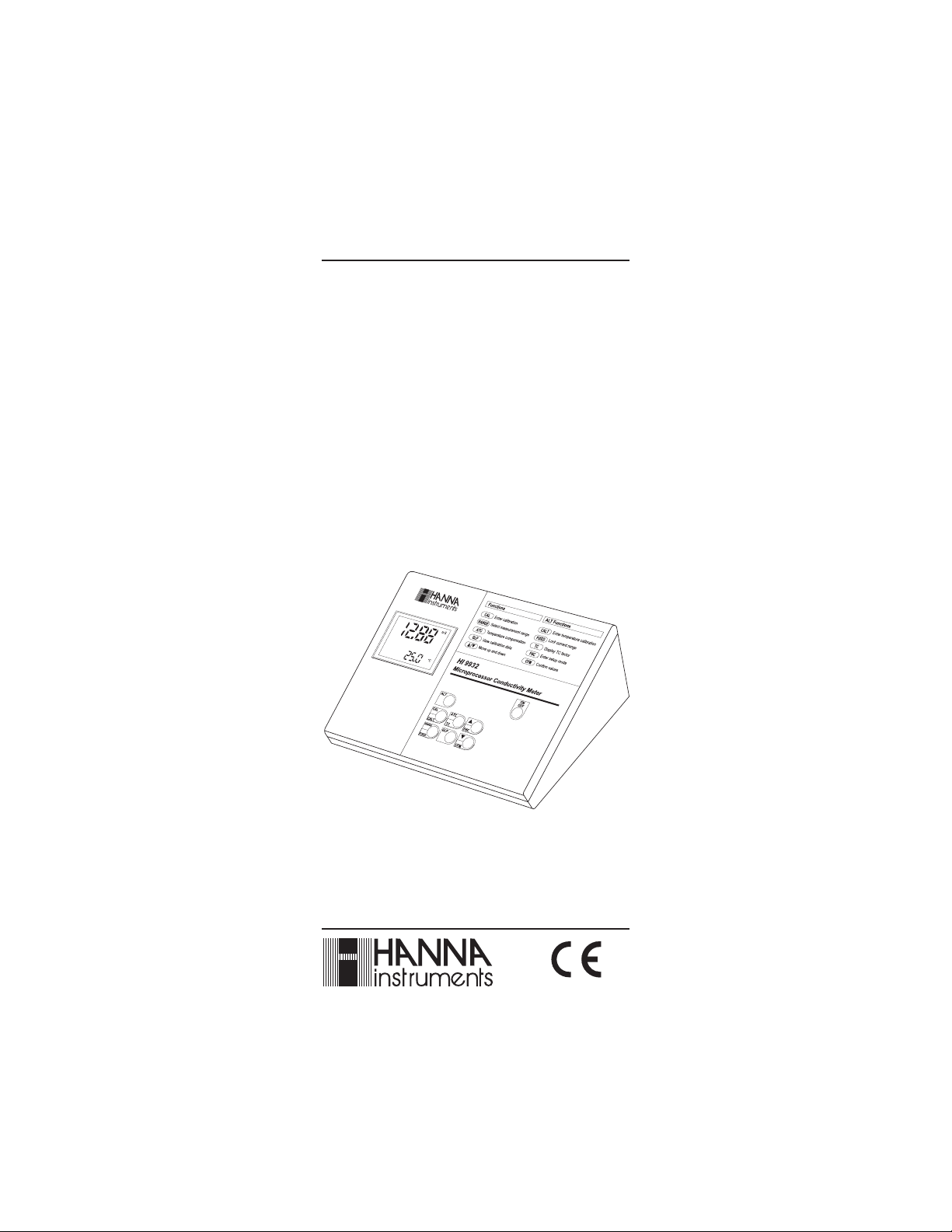
HI 9932
Autoranging Bench
Microprocessor
EC/TDS/NaCl/°C
Meter
Manufacturers since 1978
This Instrument is in
Compliance with the CE Directives
Page 2

Dear Customer,
Thank you for choosing a Hanna Instruments Product.
Please read this instruction manual carefully before using the instru-
ment.
This manual will provide you with the necessary information for a
correct use of the instrument, as well as a precise idea of its versatility.
If you need additional technical information, do not hesitate to e-mail
us at tech@hannainst.com.
These instruments are in compliance with
TABLE OF CONTENTSTABLE OF CONTENTS
TABLE OF CONTENTS
TABLE OF CONTENTSTABLE OF CONTENTS
PRELIMINARY EXAMINATION .............................................................. 3
GENERAL DESCRIPTION ...................................................................... 3
FUNCTIONAL DESCRIPTION .................................................................4
SPECIFICATIONS................................................................................ 5
CONNECTIONS .................................................................................. 6
TAKING MEASUREMENTS ................................................................... 7
AUTORANGING ..................................................................................8
TEMPERATURE COMPENSATION .......................................................... 8
EC / TDS CALIBRATION ...................................................................... 9
NaCl CALIBRATION .......................................................................... 10
TEMPERATURE CALIBRATION ............................................................ 11
TEMPERATURE ADJUSTMENT ............................................................ 11
CONDUCTIVITY VS. TEMPERATURE CHART ........................................... 12
SETUP ........................................................................................... 13
GOOD LABORATORY PRACTICE ...........................................................14
DATA TRANSFER TO PC .................................................................... 16
PROBE MAINTENANCE ..................................................................... 16
ACCESSORIES ................................................................................. 17
WARRANTY ..................................................................................... 18
CE DECLARATION OF CONFORMITY .................................................... 19
directives.
All rights are reserved. Reproduction in whole or in part is prohibited
without the written consent of the copyright owner,
Hanna Instruments Inc., 584 Park East Drive, Woonsocket, Rhode
Island, 02895 , USA.
Visit our Internet Home Page:
http://www.hannainst.com
2
Page 3

PRELIMINARY EXAMINATIONPRELIMINARY EXAMINATION
PRELIMINARY EXAMINATION
PRELIMINARY EXAMINATIONPRELIMINARY EXAMINATION
Remove the instrument from the packing material and examine it
carefully to make sure that no damage has occurred during shipping.
If there is any damage, notify your Dealer.
Each meter is supplied complete with:
• HI 76310 Conductivity/TDS probe
• 12V DC power adapter
• Dust Cover.
Note: Save all packing material until you are sure that the instrument
functions correctly. Any defective item must be returned in its
original packaging together with the supplied accessories.
GENERAL DESCRIPTIONGENERAL DESCRIPTION
GENERAL DESCRIPTION
GENERAL DESCRIPTIONGENERAL DESCRIPTION
HI 9932 is a bench microprocessor-based Conductivity/TDS/NaCl/temperature meter.
The autoranging feature of the EC and TDS ranges automatically sets
the meter to the scale with the highest possible resolution.
The measurements are automatically (ATC) or manually (MTC) compensated for temperature. The temperature coefficient value is user
selectable. It is possible to disable the temperature compensation and
measure the actual conductivity.
The meter is equipped with a stability indicator.
HI 9932 includes also GLP capability and transfer of data to a
computer through an RS232 port.
In addition, the meter allows the user to enter an ID code to uniquely
identify the instrument.
3
Page 4

FUNCTIONAL DESCRIPTIONFUNCTIONAL DESCRIPTION
FUNCTIONAL DESCRIPTION
FUNCTIONAL DESCRIPTIONFUNCTIONAL DESCRIPTION
1) Liquid Crystal Display (LCD)
2) ALT key, to alternate key function
3) CAL / CALT key, to enter calibration mode
4) RANGE / FIXED key, to select measurement range or (with ALT)
to freeze the current range on the LCD
5) ATC / TC key, to select temperature compensation mode or (with
ALT) to view the temperature coefficient value
6) GLP key, to display GLP data
7) WCFM key, to move down or (with ALT) confirm values
8) VFNC key, to move up or (with ALT) enter setup mode
9) ON/OFF key, to turn the meter on and off
10)Probe Connector
11) RS232 connector.
12)Power adapter socket
4
Page 5

SPECIFICATIONSSPECIFICATIONS
SPECIFICATIONS
SPECIFICATIONSSPECIFICATIONS
Range EC 0.00 to 29.99 µS/cm
(Autoranging) 30.0 to 299.9 µS/cm
300 to 2999 µS/cm
3.00 to 29.99 mS/cm
30.0 to 200.0 mS/cm
Up to 500.0 mS/cm actual
(*)
Conductivity
TDS 0.00 to 14.99 ppm
(Autoranging) 15.0 to 149.9 ppm
150 to 1499 ppm
1.50 to 14.99 g/L
15.0 to 100.0 g/L
Up to 400.0 g/L actual
(*)
TDS (with 0.80 factor)
NaCl 0.0 to 400.0 %
Temp. 0.0 to 60.0 C
Resolution EC 0.01 µS/cm (from 0.00 to 29.99 µS/cm)
0.1 µS/cm (from 30.0 to 299.9 µS/cm)
1 µS/cm (from 300 to 2999 µS/cm)
0.01 mS/cm (from 3.00 to 29.99 mS/cm)
0.1 mS/cm (over 30.0 mS/cm)
TDS 0.01 ppm (from 0.00 to 14.99 ppm)
0.1 ppm (from 15.0 to 149.9 ppm)
1 ppm (from 150 to 1499 ppm)
0.01 g/L (from 1.50 to 14.99 g/L)
0.1 g/L (over 15.0 g/L)
NaCl 0.1 %
Temp. 0.1C
Accuracy EC ±1% of reading ± (0.05 µS/cm or 1 digit,
whichever greater)
TDS ±1% of reading ± (0.03 ppm or 1 digit,
whichever greater)
NaCl ±1% of reading
Temp. ±0.4C
Typical EMC EC ±1% of reading
Deviation TDS ±1% of reading
NaCl ±1% of reading
Temp. ±0.1 C
(*)
Actual conductivity (or TDS) is the non-temperature compensated conductivity (or
TDS) value of a solution.
5
Page 6
EC Calibration 1 point with 6 memorized buffers
84,1413,5000,12880,80000,111800 µS/cm
NaCl Calibration 1 point with HI 7037 buffer (optional)
Temperature 2 points at 0 and 50C
Calibration (plus ±1C adjustment)
Temperature Automatic or Manual from 0 to 60C
Compensation (can be disabled to measure actual conductivity)
Temperature 0.00 to 6.00 %/C (for EC and TDS only)
Coefficient Default value is 1.90%/C
TDS Factor 0.40 to 0.80 (default value is 0.50)
Probe HI 76310 Platinum 4-ring probe, K=1 nomi-
nal and built-in temperature sensor (included)
GLP Storing of last calibration data
Serial Interface RS232 - downloading of last calibration data
Auto Off After 5 minutes (can be disabled)
Power supply 12 VDC adapter (included)
Casing Bench-top
Environment 0 to 50C ; 95% RH non-condensing
Dimensions 230 x 170 x 70 mm (9.1 x 6.7 x 2.7")
Weight 1 Kg (2.2 lb.)
CONNECTIONSCONNECTIONS
CONNECTIONS
CONNECTIONSCONNECTIONS
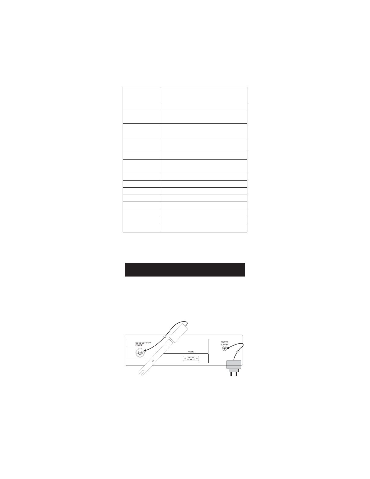
The connectors are located on the rear panel.
Connect the voltage adapter to the power adapter socket. Connect the
EC/TDS probe to the 7-pin connector. Tighten the threaded ring.
Make sure the probe sleeve is properly inserted, as shown below.
6
Page 7

TAKING MEASUREMENTSTAKING MEASUREMENTS
TAKING MEASUREMENTS
TAKING MEASUREMENTSTAKING MEASUREMENTS
Press the ON/OFF key to turn the meter on.
Immerse the probe into the solution to be tested.
The sleeve holes must be completely submerged.
Tap the probe repeatedly to remove any air bubbles
that may be trapped inside the sleeve.
If needed, press the RANGE key repeatedly until the
desired range (EC, TDS, NaCl) is selected on the
LCD.
Allow for the reading to stabilize. The upper
LCD displays the measure in the selected
range while the temperature is displayed on
the lower LCD.
Notes
I If the meter displays "----" the reading is out of range.
II If the reading is unstable, the stability indicator "
III The "gm" indication on the LCD means g/L.
IV Make sure the meter is calibrated before taking measurements.
V If measurements are taken successively in different samples, to
have accurate readings it is recommended to rinse the probe
thoroughly with deionized water before immersion in the samples.
VI TDS reading is obtained multiplying the EC reading by the TDS
factor, which has a default value of 0.50. It is possible to
change the TDS factor in the 0.40 to 0.80 range by entering
the setup mode and selecting the "tdS" item (see SETUP for
details).
VII When the use of an alternate function (FNC, CFM,FIXED,TC and
CALT) is requested, press and hold the ALT key first and then
the second key.
" blinks.
7
Page 8

AUTORANGINGAUTORANGING
AUTORANGING
AUTORANGINGAUTORANGING
The EC and TDS scales are autoranging. The meter automatically sets
the scale with the highest possible resolution.
By pressing ALT+FIXED, the autoranging
feature is disabled and the current range
is frozen on the LCD. "F1" symbol blinks
on the LCD.
To restore the autoranging option press ALT+FIXED again.
Note: Autoranging is automatically restored if the range is changed, if
the setup or calibration modes are entered and if the meter is
turned off and back on again.
TEMPERATURE COMPENSATIONTEMPERATURE COMPENSATION
TEMPERATURE COMPENSATION
TEMPERATURE COMPENSATIONTEMPERATURE COMPENSATION
Three options of compensating temperature are available:
Automatic (Atc): The probe has a built-in temperature sensor; the
value of the temperature is used to automatically compensate the EC/
TDS reading using 25C as reference temperature. This is the default
option.
Manual (Mtc): The temperature value, shown on the lower LCD, can
be manually set with the arrow keys. The compensation is referenced
at 25C. The "C" symbol blinks when this option is active.
No Compensation (notc): The temperature value shown on the lower
LCD is not taken into account. The reading displayed on the upper LCD
is the actual EC or TDS value. The "C" and "%TC" symbols blink when
this option is active.
To select the desired option press the ATC key until
the option is briefly displayed on the LCD.
Note: The default compensation mode is ATC.
If temperature compensation is active, measurements are compen-
sated using a default temperature coefficient of 1.90 %/C.
It is possible to select a different temperature coefficient (TC) in the
0.00 to 6.00 %/C range. To change the TC factor enter the setup
mode and select the "tc" item (see SETUP for details).
The current temperature coefficient can be
quickly viewed pressing ALT+TC. The value
is briefly displayed on the lower LCD.
8
Page 9

EC/TDS/MEC/TDS/M
EC/TDS/M
EC/TDS/MEC/TDS/M
Calibration is a 1-point procedure. Selectable calibration points are:
0.0, 84.0µS, 1413µS, 5.00mS, 12.88mS, 80.0mS,111.8mS.
To enter EC calibration select the EC range and press
the CAL key.
Note: TDS reading is automatically derived from the EC reading and
no specific calibration for TDS is needed. Pressing CAL while
TDS range is selected has no effect.
Rinse the probe with some of the calibration solution or
deionized water. Immerse the probe into the solution.
The sleeve holes must be completely submerged. Tap
the probe repeatedly to remove any air bubbles that
may be trapped inside the sleeve.
For zero calibration, just leave the dry probe in air.
ΩΩ
CALIBRATION CALIBRATION
Ω
CALIBRATION
ΩΩ
CALIBRATION CALIBRATION
The indications "BUF" and "CAL" are displayed. The upper LCD shows the uncalibrated
EC reading. The lower LCD shows the buffer
value. The stability indicator "
Select the desired value with the V
and W keys, if necessary.
" blinks.
When the " " symbol stops blinking, the
reading is stable. The "CON" indication starts
blinking on the LCD asking for confirmation.
Press ALT + CFM to confirm the calibration.
If everything is satisfactory, the meter displays the "Stor Good" message and returns to measurement mode.
Notes
I If the uncalibrated reading is too far from the expected value,
calibration is not recognized. The "CON" indication does not
appear; the " " and "BUF" symbols blink to signal wrong or
contaminated calibration solution.
II For best results choose an EC buffer value close to the sample
to be measured.
9
Page 10

III In order to minimize any EMC interference, use plastic beakers.
IV The meter uses 1.90%/C compensation factor during calibra-
tion. If the setup item "tc" has been set to a different value,
when exiting the calibration mode the value displayed on the
upper LCD could be different from the nominal buffer value.
V It is possible to set the cell constant value directly without
following the calibration procedure. To set the cell constant
enter the setup mode and select "CEL" (see SETUP for details).
NN
aa
CC
ll
CALIBRATION CALIBRATION
N
a
C
l
CALIBRATION
NN
aa
CC
ll
CALIBRATION CALIBRATION
Calibration is 1-point at 100.0% NaCl. Use the HI 7037 calibration
solution (sea water solution) as a 100% NaCl standard solution.
To enter NaCl calibration select the NaCl range and
press the CAL key.
Rinse the probe with some of the calibration solution or
deionized water. Immerse the probe into HI 7037 solution. The sleeve holes must be completely submerged.
Tap the probe repeatedly to remove any air bubbles that
may be trapped inside the sleeve.
The indications "BUF" and "CAL" are displayed. The upper LCD shows the uncalibrated
NaCl reading in percentage. The lower LCD
shows "100".
When the " " symbol stops blinking, the
reading is stable. The "CON" indication starts
blinking on the LCD asking for confirmation.
Press ALT + CFM to confirm the calibration.
If everything is satisfactory, the meter displays the "Stor Good" message and returns to measurement mode.
Note: If the uncalibrated reading is too far from the expected value,
the calibration is not recognized. The "CON" indication does not
appear; the " " and "BUF" symbols blink to signal wrong or
contaminated calibration solution.
Note: The meter uses 1.90%/C compensation factor during calibra-
tion. If the setup item "tc" has been set to a different value,
when exiting the calibration mode the value displayed on the
LCD could be different from the nominal calibration value.
10
Page 11

TEMPERATURE CALIBRATIONTEMPERATURE CALIBRATION
TEMPERATURE CALIBRATION
TEMPERATURE CALIBRATIONTEMPERATURE CALIBRATION
((
for technical personnel only)for technical personnel only)
(
for technical personnel only)
((
for technical personnel only)for technical personnel only)
The calibration is 2 points at 0.0, 50.0C.
• Immerse the probe in a 0C temperature bath.
• Press ALT+CALT to enter temperature calibration mode.
• The lower LCD displays "0.0 C"; "BUF" and "CAL" tags appear.
• When the reading is stable, "CON" symbol starts to blink.
• Press ALT+CFM to confirm. The lower LCD displays 50.0C.
• Immerse the probe in a 50C temperature bath.
• When the reading is stable, "CON" symbol starts to blink.
• Press ALT+CFM to confirm and return to normal operation.
TEMPERATURE ADJUSTMENTTEMPERATURE ADJUSTMENT
TEMPERATURE ADJUSTMENT
TEMPERATURE ADJUSTMENTTEMPERATURE ADJUSTMENT
The temperature reading can be manually fine-tuned by following this
procedure:
Press ALT+CALT to enter the temperature
calibration mode.
Press CAL to enter the temperature adjustment mode.
The upper and lower LCD will display the current
temperature reading.
Adjust the temperature reading on
the upper LCD using the arrow keys.
The maximum adjustment is ±1C
around current reading.
Press ALT+CFM to confirm. The meter
returns to measurement mode and displays the new temperature.
Note: Press ALT+CALT to escape without any changes.
Note: It is possible to enter the temperature adjustment mode only if
the probe is connected.
11
Page 12

CONDUCTIVITY VERSUSCONDUCTIVITY VERSUS
CONDUCTIVITY VERSUS
CONDUCTIVITY VERSUSCONDUCTIVITY VERSUS
TEMPERATURE CHARTTEMPERATURE CHART
TEMPERATURE CHART
TEMPERATURE CHARTTEMPERATURE CHART
The conductivity of an aqueous solution is the measure of its ability to
carry an electrical current by means of ionic motion.
The conductivity invariably increases with increasing temperature.
It is affected by the type and number of ions in the solution and by the
viscosity of the solution itself. Both parameters are temperature dependent. The dependency of conductivity on temperature is expressed
as a relative change per degree Celsius at a particular temperature,
commonly as percent per C.
The following table lists the temperature dependence of the HANNA
calibration buffers.
CF HI 7030 HI 7031 HI 7033 HI 7034 HI 7035 HI 7039
0 32 7150 776 64 48300 65400 2760
5 41 8220 896 65 53500 74100 3180
10 50 9330 1020 67 59600 83200 3615
15 59 10480 1147 68 65400 92500 4063
16 60.8 10720 1173 70 67200 94400 4155
17 62.6 10950 1199 71 68500 96300 4245
18 64.4 11190 1225 73 69800 98200 4337
19 66.2 11430 1251 74 71300 100200 4429
20 68 11670 1278 76 72400 102100 4523
21 69.8 11910 1305 78 74000 104000 4617
22 71.6 12150 1332 79 75200 105900 4711
23 73.4 12390 1359 81 76500 107900 4805
24 75.2 12640 1386 82 78300 109800 4902
25 77 12880 1413 84 80000 111800 5000
26 78.8 13130 1440 86 81300 113800 5096
27 80.6 13370 1467 87 83000 115700 5190
28 82.4 13620 1494 89 84900 117700 5286
29 84.2 13870 1521 90 86300 119700 5383
30 86 14120 1548 92 88200 121800 5479
31 87.8 14370 1575 94 90000 123900 5575
HI 8030 HI 8031 HI 8033 HI 8034 HI 8035 HI 8039
(µS/cm) (µS/cm) (µS/cm) (µS/cm) (µS/cm) (µS/cm)
12
Page 13

SETUPSETUP
SETUP
SETUPSETUP
Setup is used to view or change the instrument parameters.
To enter setup press ALT+FNC when the
meter is in measurement mode.
"Set" is displayed on the upper LCD. The
lower LCD displays the blinking code of the
current setup item.
Select the desired setup item using
the V or W key.
Press ALT+CFM to confirm.
Note: If ALT+FNC are pressed before item confirmation, the meter
will escape and return to measurement mode.
Once the desired setup item has been selected, its current value blinks (if it is a
changeable parameter).
To change the value use the V or W
key.
If there is another part of the item to be set
(e.g. month in setting up the correct date),
press RANGE to gain access to it.
The value of the flashing part can be changed
with the arrow keys.
Press ALT+CFM to confirm.
Note: Press ALT+FNC before confirmation to escape without chang-
ing the previously set value.
13
Page 14

The following table lists the setup items, their valid range of values
and the factory settings (default):
Item Description Valid values Default
tc Temp. compensation coeff. 0.00 to 6.00 %/C 1.90
tcE Temp. compensation mode Atc, Mtc, notc Atc
tdS TDS factor 0.40 to 0.80 0.50
CEL Cell constant (K) 0.500 to 1.700 1.000
AoF Auto-Off enabled On, OFF OFF
YEA Year 1999 to 2098 1999
dAt Date (DD.MM) 01.01 to 31.12 01.01
hou Time (hh.mm) 00.00 to 23.59 00.00
id Meter identification code 0000 to 9999 0000
vEr Firmware release
Notes:
I Once enabled, the Auto-Off time is fixed at 5 minutes.
II Assigning an ID code is helpful in identifying a particular meter
from others.
GOOD LABORATORY PRACTICEGOOD LABORATORY PRACTICE
GOOD LABORATORY PRACTICE
GOOD LABORATORY PRACTICEGOOD LABORATORY PRACTICE
Good Laboratory Practice (GLP) is a set of functions that allows the
storage and retrieval of data regarding the status of the system.
After a successful calibration, the meter automatically stores the date
and time of calibration, the calibration solution used and the resulting
cell constant value. All such information can be recalled by the user.
To view last calibration data select the desired
range (EC or NaCl) and press the GLP key.
The first information appearing on the LCD
is the meter "id" code.
By repeatedly pressing the RANGE key, the GLP
data are displayed in the following order:
Last calibration date.
14
Page 15

Last calibration year.
Last calibration time.
Cell constant value (K).
Offset value.
This information is displayed only if the
last calibration was performed at 0.00 µS.
Calibration solution used.
If the cell constant was changed after cali-
bration (through "CEL" setup function), this
information is not displayed.
For NaCl GLP, the last parameter is not the
nominal value of the calibration solution
but the actual conductivity (non-temperature compensated) and the temperature of
the calibration solution used.
If the RANGE key is pressed when the last parameter is displayed, the
meter returns to measurement mode.
Notes
I It is possible to escape from GLP at any time by pressing
ALT+GLP.
II If the calibration procedure was never performed, after display-
ing the ID code the LCD will show the "no CAL" message. Press
RANGE or ALT+GLP to escape to measurement mode.
III Last calibration data are available for EC and NaCl only. No
calibration data can be recalled for TDS. If the meter is in TDS
mode, by pressing ALT+GLP it is only possible to view the ID
code. Press ALT+GLP again to return to measurement mode.
IV The meter has an internal lithium battery that allows to cor-
rectly update the date and time even if the power is disconnected.
15
Page 16

DATA TRANSFER TO PCDATA TRANSFER TO PC
DATA TRANSFER TO PC
DATA TRANSFER TO PCDATA TRANSFER TO PC
Connect the meter
4). Use HI 920010 (9 to 9-pin) connection cable.
The meter must be in measurement mode to communicate.
The meter RS232 port is optoisolated and transmits data with a Baud
rate of 2400 bps.
Retrieve the GLP data and request the meter parameters and the
current reading (of the current range only) from the PC directly. It is
also possible to send a command from the PC to set the meter in a
different range.
To communicate with the PC use the HI 92000 communication soft-
ware. The software is provided with an exhaustive on-line guide of all
the commands available and allows data printing, plotting and exporting.
to a PC through the RS232 output (#11 on page
PROBE MAINTENANCEPROBE MAINTENANCE
PROBE MAINTENANCE
PROBE MAINTENANCEPROBE MAINTENANCE
Rinse the probe with clean water after measurements. If a more
thorough cleaning is required, remove the probe sleeve and clean the
probe with a cloth or a nonabrasive detergent. Make sure to reinsert
the sleeve onto the probe properly and in the right direction. After
cleaning the probe, recalibrate the instrument.
The platinum rings support is made of glass. Take great care while
handling the probe.
16
Page 17

ACCESSORIESACCESSORIES
ACCESSORIES
ACCESSORIESACCESSORIES
CONDUCTIVITY BUFFER SOLUTIONS
HI 70030P 12880 µS/cm (µmho/cm), 20mL sachets (25 pcs.)
HI 7030L 12880 µS/cm (µmho/cm), 460mL bottle
HI 7030M 12880 µS/cm (µmho/cm), 230mL bottle
HI 70031P 1413 µS/cm (µmho/cm), 20mL sachets (25 pcs.)
HI 7031L 1413 µS/cm (µmho/cm), 460mL bottle
HI 7031M 1413 µS/cm (µmho/cm), 230mL bottle
HI 70033P 84 µS/cm (µmho/cm), 20mL sachets (25 pcs.)
HI 7033L 84 µS/cm (µmho/cm), 460mL bottle
HI 7033M 84 µS/cm (µmho/cm), 230mL bottle
HI 7034L 80000 µS/cm (µmho/cm), 460mL bottle
HI 7034M 80000 µS/cm (µmho/cm), 230mL bottle
HI 7035L 111800 µS/cm (µmho/cm), 460mL bottle
HI 7035M 111800 µS/cm (µmho/cm), 230mL bottle
HI 70039P 5000 µS/cm (µmho/cm), 20mL sachets (25 pcs.)
HI 7039L 5000 µS/cm (µmho/cm), 460mL bottle
HI 7039M 5000 µS/cm (µmho/cm), 230mL bottle
HI 8030L 12880 µS/cm (µmho/cm), 460mL FDA approved bottle
HI 8031L 1413 µS/cm (µmho/cm), 460mL FDA approved bottle
HI 8033L 84 µS/cm (µmho/cm), 460mL FDA approved bottle
HI 8034L 80000 µS/cm (µmho/cm), 460mL FDA approved bottle
HI 8035L 111800 µS/cm (µmho/cm),460mL FDA approved bottle
HI 8039L 5000 µS/cm (µmho/cm), 460mL FDA approved bottle
HI 7037L 100% NaCl sea water standard solution, 460mL
PROBE CLEANING SOLUTIONS
HI 7061M General Cleaning Sol., 230mL bottle
HI 7061L General Cleaning Sol., 460mL bottle
HI 8061M General Cleaning Sol., 230mL FDA approved bottle
HI 8061L General Cleaning Sol., 460mL FDA approved bottle
OTHER ACCESSORIES
HI 76310 platinum 4-ring conductivity/TDS probe with tempera-
ture sensor and 1m (3.3') cable.
HI 710005 12VDC voltage adapter (US plug)
HI 710006 12VDC voltage adapter (European plug)
HI 920010 9 to 9-pin connection cable
HI 92000 Windows compatible software
17
Page 18

WARRANTYWARRANTY
WARRANTY
WARRANTYWARRANTY
All Hanna Instruments meters are warranted for two years against
defects in workmanship and materials when used for their intended
purpose and maintained according to instructions. The electrodes
and the probes are warranted for a period of six months. This
warranty is limited to repair or replacement free of charge.
Damages due to accident, misuse, tampering or lack of prescribed
maintenance are not covered.
If service is required, contact the dealer from whom you purchased the
instrument. If under warranty, report the model number, date of
purchase, serial number and the nature of the failure. If the repair is
not covered by the warranty, you will be notified of the charges
incurred. If the instrument is to be returned to Hanna Instruments, first
obtain a Returned Goods Authorization number from the Customer
Service department and then send it with shipping costs prepaid.
When shipping any instrument, make sure it is properly packaged for
complete protection.
To validate your warranty, fill out and return the enclosed warranty
card within 14 days from the date of purchase.
Hanna Instruments reserves the right to modify the design, construction and appearance of its products without advance notice.
18
Page 19

CE DECLARATION OF CONFORMITYCE DECLARATION OF CONFORMITY
CE DECLARATION OF CONFORMITY
CE DECLARATION OF CONFORMITYCE DECLARATION OF CONFORMITY
Recommendations for Users
Before using this product, make sure that it is entirely suitable for the environment in which it is used.
Operation of this instrument in residential area could cause unacceptable interference to radio and TV
equipment, requiring the operator to take all necessary steps to correct interference.
The metal bands of the probe are sensitive to electrostatic discharges. Avoid touching these metal bands
at all times.
To maintain the EMC performance of this equipment the recommended cables must be used.
Any variation introduced by the user to the supplied equipment may degrade the instruments EMC
performance.
To avoid electrical shock, do not use this instrument when voltage at the measurement surface exceeds
24VAC or 60 VDC.
To avoid damages or burns, do not perform any measurement in microwave ovens.
19
Page 20

HANNA LITERATUREHANNA LITERATURE
HANNA LITERATURE
HANNA LITERATUREHANNA LITERATURE
Hanna publishes a wide range of catalogs and handbooks
for an equally wide range of applications. The reference
literature currently covers areas such as:
• Water Treatment
• Process
• Swimming Pools
• Agriculture
• Food
• Laboratory
• Thermometry
and many others. New reference material is constantly
being added to the library.
For these and others catalogs, handbooks and leaflets,
contact your dealer or the Hanna Customer Service Center
nearest to you. To find the Hanna Office in your vicinity,
check our home page at www.hannainst.com
http://www.hannainst.comhttp://www.hannainst.com
http://www.hannainst.com
http://www.hannainst.comhttp://www.hannainst.com
MAN9932R2
11/00
 Loading...