

Page 1
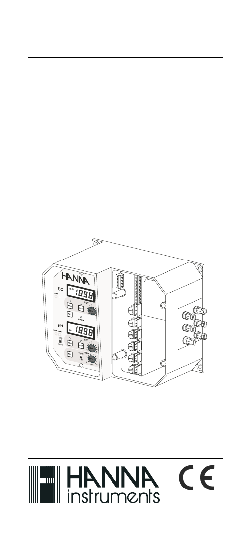
Instruction Manual
HI 9914
Wall mounted
Fertigation
Controller
Manufacturers since 1978
1
These Instruments are in
Compliance with the CE
Directives
Page 2

Dear Customer,
Thank you for choosing a Hanna Product. Please read this instruction
manual carefully before using the instrument.
This manual will provide you with the necessary information for a correct
use of the instrument, as well as a precise idea of its versatility.
If you need more technical information, do not hesitate to e-mail us at
tech@hannainst.com.
These instruments are in compliance with CE directives.
TABLE OF CONTENTS
PRELIMINARY EXAMINATION ......................................................... 3
GENERAL DESCRIPTION ................................................................. 3
MECHANICAL LAYOUT ................................................................... 5
FUNCTIONAL DESCRIPTION ........................................................... 6
SPECIFICATIONS........................................................................... 8
INSTALLATION ...........................................................................10
TANK ASSEMBLY SETUP .............................................................. 10
CONNECTIONS AND WIRING........................................................ 12
CONTROLLER START-UP .............................................................. 18
NORMAL OPERATION .................................................................19
ALARM CONDITIONS .................................................................. 22
CONTROLLER SETTINGS............................................................... 23
CALIBRATION ............................................................................. 26
pH ELECTRODE CONDITIONING & MAINTENANCE ........................... 29
CONDUCTIVITY PROBE MAINTENANCE ........................................... 31
ACCESSORIES ............................................................................. 32
APPENDIX .................................................................................. 33
A-pH VALUES AT VARIOUS TEMPERATURES ............................. 33
B-NUTRIENT SOLUTION - TABLES ........................................... 34
C-INSTALLATION EXAMPLES.................................................... 36
WARRANTY ................................................................................ 38
CE DECLARATION OF CONFORMITY ............................................... 39
2
Page 3

PRELIMINARY EXAMINATION
Remove the instrument from the packing material and examine it carefully to make sure that no damage has occurred during shipping. If there
is any noticeable damage, notify your Dealer.
Note: Save all packing materials until you are sure that the instrument
functions correctly. Any defective item must be returned in the
original packaging, together with the supplied accessories.
• Read carefully the instructions before using the instrument.
• Never install the controller outdoors, in a wet or humid area or under
direct sun light. Nor install the controller where liquids may be
sprayed or poured on it.
• The instrument has to be connected to a mains socket.
• The instrument’s mains power line is protected by a 400mA fuse. Use
only a 400mA fuse for replacement.
• The instrument’s dosage, water nozzle, feeding pump, circulation
pump and alarm terminals are protected by separate 2A fuses. Use
only 2A fuses for replacement.
GENERAL DESCRIPTION
HI 9914 Wall Mounted Fertigation Controller is designed to meet specific
process control requirements in agricultural, horticultural and hydroponics applications.
The controller is provided with two measuring channels, one for pH and
one for Conductivity. The actual values of pH and Conductivity are
displayed separately on two large LCDs with backlight feature for a best
easy reading.
The EC probe is designed with a built-in temperature sensor which allows
the controller to automatically compensate for the temperature effect.
The matching pin prevents potential grounding problems and thus
ensure longer life to the pH electrode.
The controller includes two regulators for pH and Conductivity, each of
them can be adjusted from the front panel and the setpoint values will
be displayed.
The conductivity regulator adds fertilizer in order to increase the conduc-
3
Page 4

tivity of the irrigation water, while the pH regulator can be set for high
or low pH correction.
For a better result, the Conductivity and pH controls are time separated
and a timed operation mode avoids overdosing of fertilizer or acid.
The controller is designed with relay outputs for pH and Conductivity
control (2A/240V), each one corresponding to a status LED for visual
check.
Three level sensors are used to offer the best control of water level, alarm
conditions and irrigation sequences.
The beginning of the irrigation can be triggered through an external
signal, while an additional input allows to restart the cycle at any time.
The good water composition is signaled on the front panel and with an
external signal for remote operating purposes.
The controller is equipped with an alarm system activated when an
unusual working condition occurs.
A humidity detector can be used to stop the controller if any leakage is
detected.
Water nozzle, Circulation pump, Feeding pump and Alarm are equipped
with 2A (240V) relays.
Two models of HI9914 controller are available, according to the required
power supply: 220/240V or 110/115V, at 50/60Hz.
4
Page 5
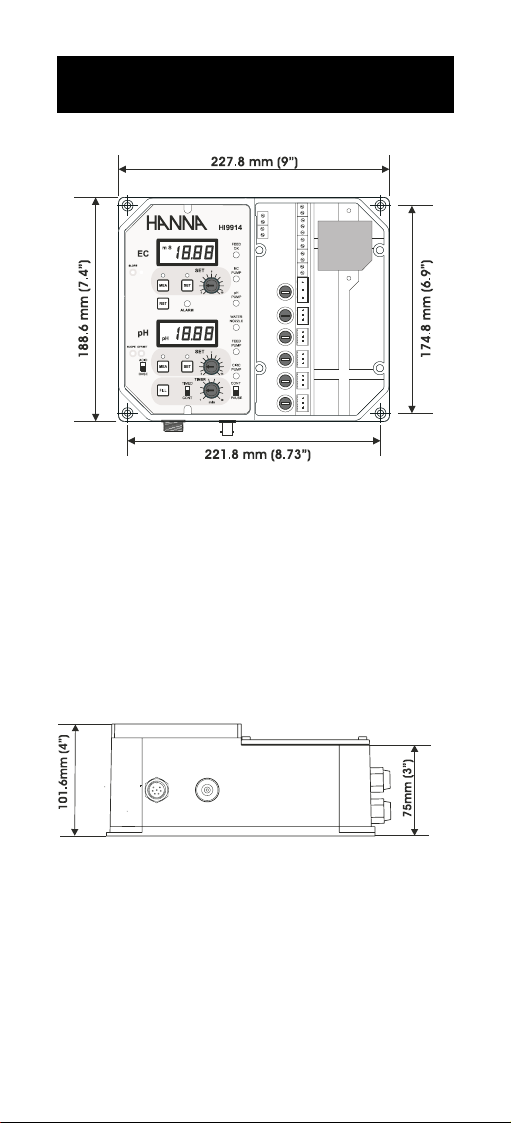
MECHANICAL LAYOUT
Front view
The molded mounting holes in the 4 corners provide for quick and secure
installation. No additional tool is needed. All the electrical connections
and control are located on the front panels so that adjustments can be
made without removing the unit.
Bottom view
The modular design isolates the control circuitry from the contacts, making possible to wire the connections and then close the compartment.
Adjustments can be made through the “control area” (left panel),
without open the connection compartment (right panel).
5
Page 6
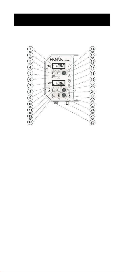
FUNCTIONAL DESCRIPTION
LEFT PANEL
1. LCD for Conductivity readings
2. EC SET button
3. EC slope adjustment trimmer
4. EC MEAsure button
5. Alarm LED
6. Reset button
7. LCD for pH readings
8. pH slope adjustment trimmer
9. pH offset adjustment trimmer
10. Acid / Base selector switch
11. pH MEAsure button
12. pH SET button
13. FILL button
14. Feed OK LED
15. EC setpoint knob
16. EC pump LED
17. pH pump LED
18. Water nozzle LED
19. Feed pump LED
20. pH setpoint knob
21. Circulation pump LED
22. RUN/STOP switch for Circulation pump
23. Timer knob
24. Timer mode selection switch
25. BNC connector for pH electrode
26. DIN connector for EC probe
6
Page 7

RIGHT PANEL
1. Connections for matching pin
2. EC analog output
3. pH analog output
4. Level sensors input
5. Mains power fuse
6. Fuse for pH and EC correction dosing pumps
7. Fuse for Water nozzle relay
8. Fuse for Feeding pump
9. Fuse for Circulation pump
10. Fuse for Alarm relay
11. Feed OK output
12. Connections for external fill switch
13. Irrigation start
14. Mains power transformer
15. Humidity sensor input
16. Power input
17. pH and EC pumps output
18. Water nozzle output
19. Feeding pump output
20. Circulation pump output
21. Alarm output
7
Page 8
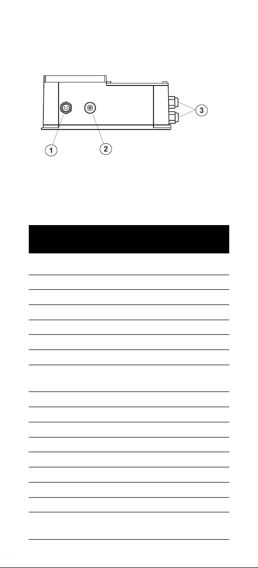
Bottom view
1. DIN connector for EC probe
2. BNC connector for pH electrode
3. Wiring access ports
SPECIFICATIONS
Conductivity
Range 0.00 to 10.00 mS/cm
Resolution 0.01 mS/cm
Accuracy (@20ºC/68ºF) ±5% Full Scale
Typical EMC deviation ±2% Full Scale
Setpoint Adjustable, from 0.50 to 10.00 mS/cm
Temp.Compensation Automatic from 0 to 50°C
Calibration Manual, through slope (80-120%) trimmer
on the front panel
Analog output 0-5V ±5% (0.5V / mS)
Controller output 2A, 220V relay
pH
Range 0.00 to 14.00 pH
Resolution 0.01 pH
Accuracy (@20ºC/68ºF) ±0.02 pH
Typical EMC deviation ±0.1 pH
Setpoint Adjustable, from 0.5 to 14.0 pH
Calibration Manual through offset (±2 pH) and slope
(80 to 120%) trimmers on the front panel
8
Page 9

Analog output 0-7V ±5% (0.5V / pH)
Controller Output 2A, 220V relay
other features
Timer Adjustable, from 1 to 10 min within a
15-minutes-time frame
Feed OK output 12V, 15 mA current source
Humidity sensor Active when resistivity is below 220 KΩ
Water nozzle output 2A, 220V relay
Circulation pump output 2A, 220V relay
Feeding pump output 2A, 220V relay
Alarm output 2A, 220V relay
Water level inputs Contact type water level sensors
User input Contact type switch
External FILL button Contact type push-button
Power supply 220/240V or 110/115V; 50/60Hz
Environment -10 to 50°C (14 to 122°F);
RH 95% max. non-condensing
Dimensions 189 x 228 x 102 mm (7.4 x 9 x 4”)
Weight 1.75 Kg (3.85 lb.)
9
Page 10

INSTALLATION
Install the HI 9914 controller on a wall, indoors, in a dry area and not
under direct sun light. Assure that liquids can not be sprayed or poured
on it. Fix the controller at a proper height to easily reach the front panels
and fix the 4 screws at the 4 corners.
Install the controller near the tank to keep short the cables of pH
electrode and Conductivity probe.
Assure the proper working voltage.
TANK ASSEMBLY SETUP
HI 9914 can work with different tank volumes and with various complexity of tank assembly. For proper operation of the controller, the tank
assemblies must be set minding the following:
- the pH electrode and EC probe should rapidly detect any modifications
in the water characteristics;
- it is recommended to use a circulation pump to mix water with fertilizer
and acid;
- fertilizer and acid should be added to the water at distance from sensors
to assure good mixing before the measuring point is reached;
- make sure that the pH electrode is always wet;
- the level sensors must be in the correct order, bottom to top: low level,
normal level and high (alarm) level;
- place the sensors in the area with the minimum waves amplitude;
- when a level is reached, the corresponding level sensor will close the
contact;
- the humidity detector must be placed outside the tank, where water
leakage can be detected;
- the inlets for the circulation and the feeding pumps must be under the
minimum water level (low level sensor);
- the normal level sensor must be used in all tank arrangements;
- if the high (alarm) level sensor is not used, leave the pin unconnected;
- if the low-level sensor is not used, connect the corresponding pin to the
common;
- if the humidity sensor is not used, leave the pin unconnected;
- for activate external refill, press the corresponding push-button.
10
Page 11
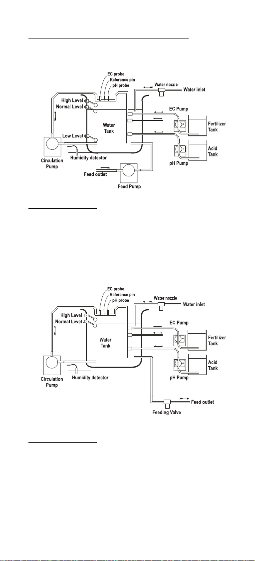
Typical arrangements for the Tank assembly
Complete tank assembly: all the sensors and pumps are mounted; the
best control of water composition and irrigation sequence is assured. The
inlet and outlet of the circulation pump are below the Low Level to avoid
that the pH electrode remains dry.
Simplified tank assembly: the low level detector is not used; the controller
does not react if the water level is too low.
Note: If a feed pump is used, provide a little water volume to keep
always the level in the tank above the circulation pump inlet.
Note: The inlet of the circulation pump must be below its outlet to avoid
damages to the pump itself.
11
Page 12
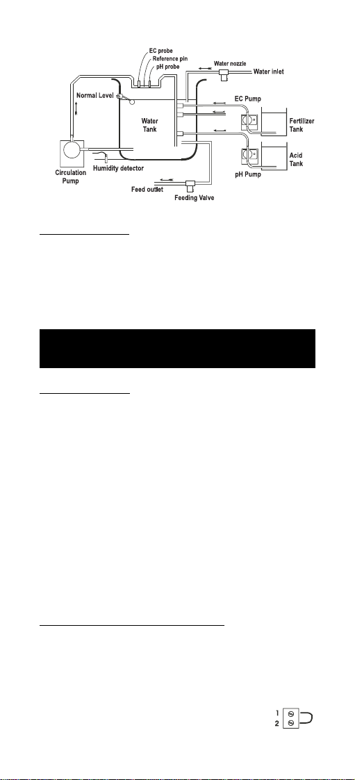
Minimal tank assembly: only the normal level sensor is used, the irrigation is made manually, regardless of the water composition or level. The
controller will refill the tank if the water goes under normal level for about
15 minutes or if the fill button is pressed.
Note: The inlet of the circulation pump must be below its outlet to avoid
damages to the pump itself.
CONNECTIONS AND WIRING
Wiring the controller
• Make sure the power supply is disconnected.
• Make sure all the auxiliary power sources are off.
• Unscrew the 4 screws from the right hand panel and remove the lid
and the gasket.
• Thread the wires through the access port on the right hand side of the
controller.
• Before connecting the controller to the mains, wire it completely,
connect the pumps, valves, alarm, probes, level sensors and user
input.
• Replace the lid. Connect the controller to mains line.
• Turn on all the auxiliary sources.
pH electrode and ground probe connections
• Attach the in-line pH electrode (for example HI 1001) to the BNC
socket on the bottom of the controller.
• Use the matching pin (differential input) to prevent potential grounding problems and thus ensure longer life to the electrode.
• If the matching pin is not used, short pin 1 and pin
2 of the external connector located in the right panel.
12
Page 13

• If the matching pin is used, connect
the matching pin terminal to the connector pin 2 located on the right panel.
• Immerse the matching pin near the pH electrode.
Conductivity probe connection
• Attach the conductivity probe (HI7632/D or HI3003/D) to the DIN
socket located on the bottom of the controller. Align the guide on the
connector with the socket, push-in the connector and tighten the
retainer ring.
• The probe is provided with a built-in temperature sensor, which allows
automatic temperature compensation of the readings.
Level inputs connections
All level sensors must have a contact type output.
If the water level is above the sensor position, the corresponding contact
is closed. If the water is below the sensor, the contact is open.
Each sensor will be connected between the INPUT COMMON (pin 9) and
the corresponding input pin (LOW LEVEL, NORM LEVEL, HIGH/ALARM
LEVEL).
13
Page 14

• Place the low-level sensor to indicate the minimum water level for the
correct function of both the circulation and feeding pumps.
• Connect the sensor between INPUT COMMON and LOW LEVEL pins.
• Place the normal-level sensor to indicate the filling level when the tank
is full.
• Connect the sensor between INPUT COMMON and NORMAL LEVEL pins.
• Place the alarm-level sensor to limit the highest water level.
• Connect the sensor between INPUT COMMON and HIGH (ALARM) LEVEL
pins.
Note: The level sensors act correctly if the sensor switch is closed when the
water is above the corresponding level
Irrigation start connection
Connect the irrigation-start switch
between INPUT COMMON and IR-
RIGATION START pins.
Irrigation can be controlled by:
• using a switch connected between the INPUT COMMON and IRRIGA-
TION START: the irrigation is started by closing the switch, and lasts
until the contact is open.
• using a 5V-logic signal, connected to the IRRIGATION START and
referred to INPUT COMMON: the irrigation starts at level “0” (0V)
and stops at level “1” (5V).
• using a level sensor that will be open when the desired level is
reached: the controller will irrigate until the desired level is reached,
and the irrigation will restart if the water falls below this level.
14
Page 15

External fill button connection
• Connect the button
between FILL and IN-
PUT COMMON pins.
• The tank will be immediately filled with
water if the external
fill button is pressed
and the water level is
below the normal level
float.
External FEED OK connection
This output is a current source from the FEED OK pin.
• Connect a LED, buzzer or other
device between FEED OK and IN-
PUT COMMON pins.
• When the water composition is good
for irrigation, the FEED OK will
source about 15mA and activate
the device.
Analog output connections
• Connect an external device between the
EC+ and EC- (for Conductivity signal) or
pH+ and pH- (for pH signal) pins.
• The output voltage is related to the value displayed on LCD. For EC the
output will be 0V for 0.00 on LCD and 5V for 10.00 on LCD; for pH the
output will be 0V for 0.00 on LCD and 7V for 14.00 on LCD.
Note: Never connect “EC” with “pH”. Make sure there is no galvanic
connection between the EC and the pH analog outputs, otherwise
the measured values will be not reliable and probes can be
damaged.
Relay connections
The controller is provided with six relay outputs (2A, 220V) protected by
2A fuses.
When a relay is off the COMMON pin is connected with the NC pin; when
is on the COMMON pin is connected with the NO pin.
The NC pin is not accessible for the pH and EC pumps and the COMMON
15
Page 16
pin is the same, so that the voltage of the power source has to match the
working voltage of the selected device and both the pH and EC correction
pumps have to work at the same voltage.
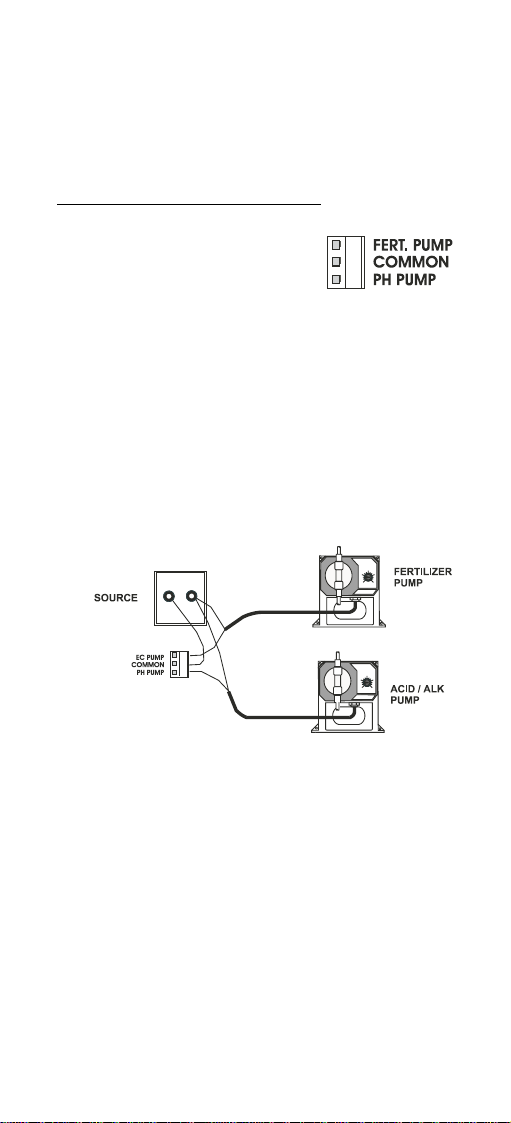
Acid and fertilizer dosing pump connection
The pH and EC correction relays (2A, 240V)
have a common pin: if the pH correction
pump is on, the COMMON pin is connected
to the pH PUMP pin; if the EC pump is
activated, the COMMON pin is connected to
the FERT. PUMP pin.
• Connect one pin of the source to the COMMON pin.
• Connect the pH correction pump between the pH PUMP pin and the
remaining pin of the source.
• Connect the EC correction pump between the FERT PUMP pin and the
remaining pin of the source.
Note: Both pH and EC correction pumps must have the same operating
voltage. The rated power of the pumps can be different.
16
Page 17

Water nozzle, Circulation and Feeding pump connection
The Water nozzle, Circulation pump and Feeding pump outputs are
relay type (2A, 240V). Both the NO (normally open) and NC (normally
closed) contacts are available to the user. If the device is off, the COM-
MON pin is connected to corresponding NC pin. If the device is on, the
COMMON pin is connected to the NO pin.
• Connect one pin of the source to the COMMON pin.
• Connect the device between the NO pin and the remaining source pin.
Alarm connection
The Alarm output is relay type (2A, 240V). Both the NO (normally open)
and NC (normally closed) contacts are available to the user. If the alarm
is off, the COMMON pin is connected to the NC pin. If the alarm is off, the
COMMON pin is connected to the NO pin.
• Connect one pin of the source to the COMMON pin of the alarm
output.
• Connect the alarm device between the NO output pin and the
remaining source pin.
17
Page 18

Main power supply connection
Before connecting the unit to the mains, make sure the controller is
completely wired and all the connections for pumps, alarm, probes, etc.
have been done.
• Connect the mains power wires to the power
supply input pins.
• Replace the right panel lid and tighten the four
provided screws.
• Connect the controller to the mains.
CONTROLLER START-UP
Before starting-up make sure the controller has been properly calibrated,
and the pH and conductivity setpoints have been adjusted (see the
following pages).
The pH electrode, conductivity probe and any reference pin must be
properly connected and wired to the controller (see the section above).
The EC probe must be immersed in the solution above the air-vent holes
on the external sleeve, and installed in such a way to minimize the
presence of air bubbles (see probe installation tips at the end of the
manual).
Remove the protective cap from the pH electrode and immerse the
electrode (at least 4cm/1.5") into the solution to be tested. Install the
electrode in such a way that it permanently lies in the solution.
The level sensors, user input, external fill button and humidity sensor
must be connected accordingly with the chosen tank assembly.
If some of the inputs are not used, they must be connected as explained
in the TANK ASSEMBLY section.
The pumps, water nozzle and alarm must be wired as described above.
Turn on the water supply and start the controller by connecting it to the
mains power supply.
The HI 9914 controls different status and gives visual information through
various LED:
- When the dosing pumps are active, the corresponding EC and pH pump
LEDs are on.
- When the circulation or the feeding pump is running, the corresponding
LED is ON.
- When the water nozzle is open, the water nozzle LED is ON.
18
Page 19

- When the water is good for irrigation, the Feed OK LED is ON.
- If any alarm condition occurs (see pag.22), the ALARM LED turns ON.
The controller can be restarted by pressing the
RESET button.
If the alarm condition is still present, the controller goes back in alarm
status.
When the controller is powered, the actual pH and conductivity values
are displayed on the two LCDs in pH and mS/cm units respectively.
NORMAL OPERATION
When the HI 9914 controller is turned on, the meter performs a status
check of the level sensors and provides the commands depending on the
input status.
All the inputs have a delay of about 1 second in order to avoid wrong
commutations caused by the waves.
Step 1:
At start-up the controller checks the normal level and low-level sensors.
• If the tank is empty, both sensors are open and the controller goes
to step 2.
• If the low-level sensor is closed and the normal level sensor is open (the
water level is between low and normal level), the controller goes to
step 3.
Step 2:
The water nozzle is activated (open) and the tank is filled with water.
When the low level is reached, the controller goes to step 3.
• If the controller remains in this status for more than 30 seconds, an
alarm condition occurs.
Step 3:
The water nozzle is open, the circulation pump is running and the tank
is filled with water.
When the normal level is reached (the normal level sensor is closed) the
controller goes to step 4.
19
Page 20

Step 4:
The water nozzle is closed, circulation pump is running and the Conductivity & pH controls are activated. The Conductivity control has the
priority over the pH control.
• If the timer feature is activated, the control is on for a selected period
(1-10 minutes) and off for the remaining period until 15 minutes.
• If both the conductivity and pH values are good for at least 30
seconds, the controller goes to step 5.
• If the normal level sensor remains open for about 15 minutes, the
controller goes back to step 3.
Step 5:
The Conductivity & pH values are good. The Circulation pump is running
and the controller waits for user input. This state is signaled on the front
panel by FEED OK LED and externally through a 15mA current between
the FEED OK and INPUT COMMON pins.
• If the water composition is not good, the controller goes back to step 4.
• If the normal level sensor remains open for about 15 minutes, the
controller goes back to step 3.
• If the FILL button (or the external fill button connected between FILL
and INPUT COMMON) is pressed while the NORMAL LEVEL sensor is
open, then the controller goes back to step 3.
• If the user input command is active (the contact is closed between the
USER INPUT and INPUT COMMON pins), the controller goes to step 6.
Step 6:
The Feeding pump is activated. The control of Conductivity and pH is
inhibited.
• If the user input becomes inactive (the contact between the USER
INPUT and INPUT COMMON pins is open), the controller goes back
to step 3.
• If the low level is reached (the low-level sensor contact is open), the
controller goes back to step 3.
• If the water remains under normal level for about 15 minutes (the
normal level contact is open), the controller goes back to step 3.
The tank can also be filled by pressing the FILL button on the front panel
(or the external fill button connected between FILL and INPUT COMMON
pins) when the irrigation is completed.
20
Page 21

If the CONT/PAUSE switch of the Circulation pump is in
CONT position, the circulation pump will act as described
above.
If the CONT/PAUSE switch of the Circulation pump is in
PAUSE position, the circulation pump will not run the step 5.
When the low-level sensor is not used, the low-level condition is not sensed
by the controller. The user must take care to stop the user input command before the water in the tank goes below the low level.
When the high (alarm) level sensor is not used and
the normal level sensor does not work properly, the
controller is unable to detect when the water reaches
the high (alarm) level. In order to stop the controller, the humidity sensor must be placed where it can
sense if the water pours down from the tank.
If the tank assembly is minimal, the irrigation takes place without using
the user input command. Only the normal level and humidity sensors are
used. The controller fills the tank at normal level and begins the Conductivity & pH correction. The user can add water at any time or wait until
a good water composition is signaled.
21
Page 22

ALARM CONDITIONS
When an alarm condition is reached, the ALARM LED turns ON and the
alarm relay contact is closed (short between the COMMON and NO pins).
All the pumps and the water nozzle are off. The Conductivity and pH
measuring channels display the EC and pH values.
An alarm condition occurs when:
• the water remains below the low level (the sensor contact is open) for
about 30 seconds;
• the high (alarm) level is reached (the sensor contact is closed);
• the humidity sensor detects water leakage;
• an impossible condition is detected, for example when the low level is
not reached and the normal level is reached.
Reset button
To return to normal function, it is necessary that:
• the water level in the tank decreases
below the high (alarm) level sensor;
• the level sensors operate correctly;
• the humidity sensor is dry;
• the RESET button is pressed.
22
Page 23

CONTROLLER SETTINGS
SETTING THE pH CONTROL
To adjust the pH setpoint:
• Press the SET button close to the pH display to read the setpoint value.
• Turn the SET knob until the display shows the desired value.
• Return to measurement mode by pressing the MEA button.
To select the dosing direction:
• Select the desired solution for pH correction by setting the ACID/BASE
switch.
• If the switch is in the ACID position, the pH pump is activated when
the pH value exceeds the setpoint. The controller will dose
acidic solution to reduce the pH until the user-selected
setpoint is reached.
• If the switch is in the BASE position, the pH pump is
activated when the pH value falls below the setpoint.
The controller will dose alkaline solution to increase the
pH until the user-selected setpoint is reached.
SETTING THE EC CONTROL
To adjust the Conductivity setpoint:
• Push the SET button close to EC display to read the setpoint value.
23
Page 24

• Turn the SET knob until the display shows the desired value.
•Turn back in measurement mode by pressing the MEA button.
Note: The internal pH and EC regulators have a small hysteresis to
prevent oscillations of the relay output that can damage the
pumps. As a result, the selected pH and EC values are equal to
the set value ± hysteresis value.
SETTING EC AND pH CONTROL TIMERS
The Timer feature is provided to avoid overdosing in a system with a long
response time. The running time of the dosing pumps is set through the
TIMER knob. The total time frame is 15 minutes. For example, if the
TIMER is set to 3 minutes, the EC or pH correction pumps will be active for
3 minutes and off for 12 minutes (3+12=15 minutes).
Setting the timer:
• In order to activate the timed dosing feature put the TIMED/CONT
switch to the TIMED position.
• To set the duty cycle of the dosing
pumps, turn the TIMER knob to the
desired position, from 1 to 10 minutes,
depending on the tank volume.
When the TIMED/CONT switch is at the CONT position, the EC and pH
correction pumps will run continuously.
24
Page 25

SETTING THE CIRCULATION PUMP WORKING REGIME
• Set the CONT/PAUSE switch to CONT to enable a continuous running
of the Circulation pump (if no ALARM condition is present).
• Set the CONT/PAUSE switch to PAUSE to stop the Circulation pump
after the good water composition is reached (do not run the Step 5).
The pump will start again when an adjustment of water composition
is needed or the irrigation takes place.
25
Page 26

CALIBRATION
Disconnect the pumps, the water nozzle and the alarm or assure that the
start of one of them will cause no damage.
ON, OFF or blinking LEDs have no effect on the measurement and
calibration of pH and EC.
pH CALIBRATION
To calibrate the controller, first set it in measurement mode by pressing
the MEA button (MEA LED is on).
Make sure the pH electrode and matching pin have been properly
connected and wired to the controller, and the meter is plugged to the
mains.
The calibration should be performed at a temperature similar to that of
the liquid to be monitored. Use the Hanna Checktemp (or other accurate thermometer) as reference.
Remove the protective cap from the electrode.
During calibration, move the electrode and the ground probe (if in use)
together from one buffer to the next.
Offset adjustment
• Rinse the tip of the electrode with pH7.01
solution (HI 7007), dip the bottom 4 cm
(1.5") of the electrode and ground probe in
the pH7.01 buffer.
• Place also the Checktemp thermometer in
the solution.
• Wait for the reading to stabilize and adjust
the OFFSET trimmer to display the correct
pH value at the measured solution temperature; e.g. 7.01 at 25°C (77°F). See the
“pH VALUES AT DIFFERENT TEMPERATURES”
section.
26
Page 27

Slope adjustment
• Rinse the electrode and the ground probe
thoroughly with water and immerse the
bottom 4 cm (1.5") in a pH10.01 (HI 7010)
or a pH4.01 (HI 7004) buffer solution.
• Stir the electrode and wait for the reading
to stabilize before adjusting the SLOPE trimmer to display the correct pH value at the
measured solution temperature; e.g. 4.01
(or 10.01) at 25°C (77°F). See the “pH
VALUES AT DIFFERENT TEMPERATURES” section.
The pH calibration is now complete.
CONDUCTIVITY CALIBRATION
To calibrate the controller, first set it in measurement mode by pressing
the MEA button (the MEA LED lights up).
Make sure the conductivity probe has been properly connected and wired
to the controller and the meter is plugged to the mains.
The calibration should be performed at a temperature similar to that of
the liquid to be monitored.
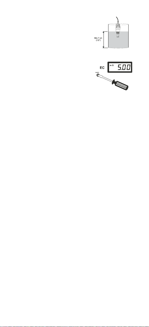
Slope adjustment
• Pour in a beaker a solution of known conductivity value, which should
be close to the sample stream to be monitored. For example, if
measurements are in the 1.2 to 2.5 EC range, choose HI 7031 (1.41
mS/cm @25°C). Similarly, if measurements are in the 4 to 6 mS/cm
range utilize HI 7031 or HI 7039 (5.00 mS/cm @25°C).
• Immerse the probe in the beaker ensuring that the holes on the probe
sleeve are completely covered.
27
Page 28
• Stir the probe and tap it gently to the
bottom of the beaker to ensure that
any air bubbles trapped inside it.
For best results, do not put the probe
close to the walls of the beaker or lying
on the bottom.
• Wait for the reading to stabilize. Adjust
the SLOPE trimmer to display the same
value as the calibration solution
@25°C. For example, with HI 7039
buffer solution, adjust the trimmer to
display “5.00”.
Note: Once the controller has been calibrated by referring to the value
@25°C of the calibration solution, all the subsequent measurements are temperature compensated to 25°C. Temperature compensation to a different temperature reference point can be obtained by calibrating the meter to that value. For example, the
conductivity value of HI 7031 @20°C is 1.28 mS/cm. By adjusting the trimmer to display this values, all the subsequent measurements will be compensated to a temperature of 20°C.
The conductivity calibration is now complete.
28
Page 29

pH ELECTRODE CONDITIONING
& MAINTENANCE
Preparation
Remove the protective cap.
DO NOT BE ALARMED IF ANY SALT DEPOSITS ARE PRESENT. This is
normal with pH electrodes and they will disappear when rinsed with
water.
During transportation tiny air bubbles may have formed inside the glass
bulb (membrane). Shake down the electrode, as you would do with a
glass thermometer to remove the bubbles.
If the bulb and/or junction are dry, soak the electrode overnight in HI
70300 Storage Solution.
Storage
To minimize noise and assure a quick response time, the glass bulb and
the junction should be kept moist at any time and not allowed to dry out.
This can be achieved by installing the electrode in such a way that it is
constantly in a well filled with the sample.
When not in use, pour a few drops of HI 70300 Storage Solution or HI
7007 pH 7.01 Buffer Solution in the protective cap and place it on the
electrode.
NEVER USE DISTILLED OR DEIONIZED WATER FOR STORING PURPOSES.
Periodic maintenance
Rinse off any salt deposits with water.
Inspect the electrode and the cable. The electrode connection cable must
be intact. There must be no points of broken insulation on the cable or
cracks on the electrode stem or bulb. If any scratches or cracks are
present, replace the electrode.
The connector must be perfectly clean and dry.
Cleaning procedure
Soak the electrode in HI 7061 General Cleaning Solution for approximately half an hour.
For a more specific cleaning procedure, refer to the electrode’s instruction
manual.
Note: After performing a cleaning procedure, rinse the electrode thor-
oughly with distilled water and recalibrate the controller.
29
Page 30

Troubleshooting
Evaluate the electrode performance based on the following:
• Noise (readings fluctuate up and down) could be due to clogged/dirty
junction:
- Dry Membrane/Junction: soak in HI 70300 Storage Solution overnight.
Check that the installation has been done to create a well to maintain
the electrode bulb constantly moist.
• Low Slope:
- Check the electrode for cracks in the glass stem or bulb (replace the
electrode if cracks are found).
- Make sure that cable and connections are neither damaged nor lying
in a pool of water or solution.
• Slow Response/Excessive Drift:
- Soak the tip in HI 7061 Solution for 30 minutes, rinse thoroughly with
distilled water and then recalibrate the meter.
Note: It is always recommended to keep at least one spare electrode
handy. When anomalies are not resolved with a simple maintenance, change the electrode (and recalibrate the controller) to see
if the problem is solved.
30
Page 31

CONDUCTIVITY PROBE MAINTENANCE
Preparation
Make sure that the protective sleeve is on the probe shaft and is intact.
Storage
Conductivity probes should be stored dry. If they are not to be used for a
while, clean and dry them thoroughly before storing them in a dry place.
Periodic maintenance
Inspect the probe and the cable. The cable used for the connection to the
controller must be intact. There must be no points of broken insulation on
the cable or cracks on the probe sleeve. If any cracks are present, replace
the probe and cable.
The connector must be clean and dry.
Cleaning procedure
Soak the probe in HI 7061 General Cleaning Solution for 1 hour.
If the probe has been left in highly concentrated fertilizer solution and
does not seem to have become clean, repeat the cleaning procedure. The
pins can also be cleaned with a cloth. The cloth has to be made of a soft
and nonabrasive material and does not scratch the pins.
Note: After performing a the cleaning procedure, rinse the probe thor-
oughly with distilled or tap water. Dry the probe and recalibrate
the controller.
Troubleshooting
• If the controller does not respond properly or constantly reads zero or
a value close to it:
- Check the probe and cable for cracks and replace it if needed.
• If the controller display shows 1. :
- The cable may be shorted or the probe broken. Replace it if needed.
• If the response seems sluggish:
- Follow the above cleaning procedure.
• If there are anomalies such as fluctuating numbers:
- Ensure that the probe has been properly mounted and constantly lies
in a well filled with solution.
31
Page 32

- Air bubbles also disturb measurements and the probe should be
installed in such a way as to minimize them.
Note: It is always recommended to keep at least one spare probe
handy. When anomalies are not resolved with a simple maintenance, change the electrode (and recalibrate the controller) to see
if the problem is alleviated.
Note: Ensure that the probe is installed in such a way that it perma-
nently lies in the solution whether in the tank or the circulation
pipe.
ACCESSORIES
pH electrodes
HI 1001 pH electrode for continuous flow-through monitoring
HI 1002 pH electrode for continuous flow-through monitoring
HI 1003 pH electrode with matching pin
EC probes
HI 7632/D Conductivity probe, ATC, 1/2” thread, with DIN
connector and 2m (6.6’) cable, for continuous flowthrough monitoring up to 3 atm pressure
HI 3003/D Conductivity probe, ATC, Pt-ring, Kynar® body,
1/2” thread, with DIN connector and 2m (6.6’)
cable, for continuous flow-through monitoring up to
6 atm pressure
pH calibration solutions
HI 7004L pH 4.01 buffer solution, 460ml bottle
HI 7007L pH 7.01 buffer solution, 460ml bottle
HI 7010L pH 10.01 buffer solution, 460ml bottle
pH electrode storage solution
HI 70300L Storage solution, 460ml bottle
EC calibration solutions
HI 7031L 1.41 mS/cm EC calibration solution, 460ml bottle
HI 7039L 5.00 mS/cm EC calibration solution, 460ml bottle
Electrode & probe cleaning solution
HI 7061L General cleaning solution, 460ml bottle
Other accessories
BL1.5, BL3, BL5, BL7, BL10, BL15, BL20
Dosing pumps with flow rate from 1.5 to 18.3 lph
(0.4 to 4.8 gph)
32
Page 33
APPENDIX - A
pH VALUES AT VARIOUS TEMPERATURES.
The temperature directly affects the pH value.
For example, if the buffer’s temperature is 25°C (77°F), calibrate the
meter to read 7.01, 4.01 or 10.01; if the temperature is 20°C, calibrate
the meter to 7.03, 4.00 or 10.06; if the temperature is 50°C, calibrate
the meter to 6.98, 4.06 or 9.82; etc.
Please refer to the following chart for a more accurate pH calibration.
TEMP pH VALUES
°C °F 4.01 6.86 7.01 9.18 10.01
0
32
4.01
6.98
7.13
9.46
10.32
5
41
4.00
6.95
7.10
9.39
10.24
10
50
4.00
6.92
7.07
9.33
10.18
15
59
4.00
6.90
7.04
9.27
10.12
20
68
4.00
6.88
7.03
9.22
10.06
25
77
4.01
6.86
7.01
9.18
10.01
30
86
4.02
6.85
7.00
9.14
9.96
35
95
4.03
6.84
6.99
9.10
9.92
40
104
4.04
6.84
6.98
9.07
9.88
45
113
4.05
6.83
6.98
9.04
9.85
50
122
4.06
6.83
6.98
9.01
9.82
55
131
4.07
6.84
6.98
8.99
9.79
60
140
4.09
6.84
6.98
8.97
9.77
65
149
4.11
6.85
6.99
8.95
9.76
70
158
4.12
6.85
6.99
8.93
9.75
33
Page 34
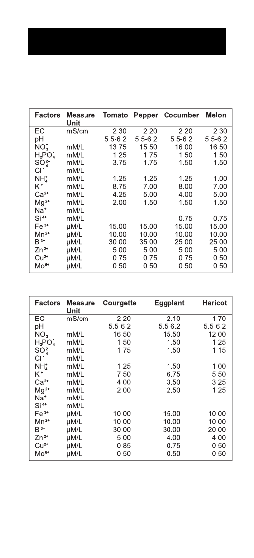
APPENDIX - B
Composition of nutrient solution for several plants growth in hydroponic
system utilized in nursery and cutting plants cultivation.
34
Page 35

Reference:
“Principi tecnico-agronomici della fertirrigazione e del fuori suolo”, pag.115,
published by “Veneto Agricoltura-Centro Sperimentale Ortofloricolo Po di
Tramontana”, coordinator Prof. F.Pimpini, Agricultural Faculty, University of Padova - Oct. 2001
35
Page 36
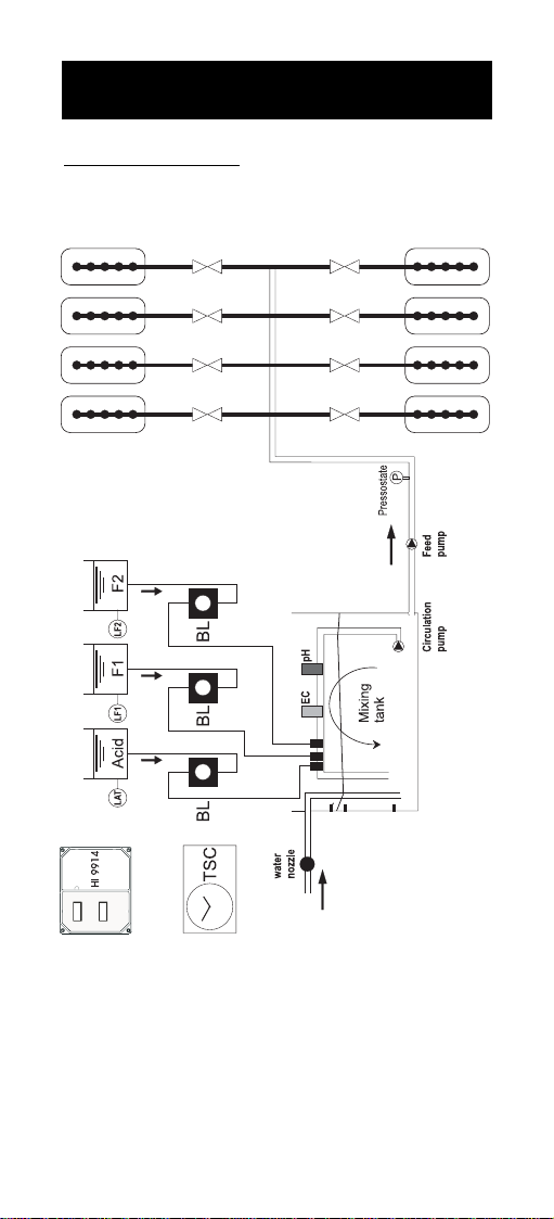
APPENDIX - C
INSTALLATION EXAMPLES
Block diagram for a typical installation of an irrigation system, with
HI9914 controller.
36
Page 37

Block diagram for an irrigation system with recirculation circuit.
37
Page 38

WARRANTY
All Hanna controllers are warranted for two years against defects in
workmanship and materials when used for their intended purpose and
maintained according to instructions. Electrodes and probes are war-
ranted for a period of six months.
Damages due to accident, misuse, tampering or lack of prescribed maintenance are not covered. This warranty is limited to free of charge or
replacement of the meter only, if any malfunctioning is due to manufacturing defects.
If service is required, contact the dealer from whom you purchased the
instrument. If under warranty, report the model number, date of purchase, serial number and the nature of failure. If the repair is not covered
by the warranty, you will be notified of the charges incurred. If the
instrument is to be returned to Hanna Instruments, first obtain a
Returned Goods Authorization Number from the Customer Service department and then send it with shipment costs prepaid. When shipping
any instrument, make sure it is properly packaged for complete protection.
All rights are reserved. Reproduction in whole or in part is prohibited without the written
consent of the copyright owner, Hanna Instruments Inc, 584 Park East Drive, Woonsocket,
Rhode Island, 02895, USA
Hanna Instruments reserves the right to modify the design, construction and
appearance of its products without advance notice.
38
Page 39

CE DECLARATION OF CONFORMITY
Recommendations for Users:
Before using this product, make sure that it is entirely suitable for the environment in
which it is used.
Operation of this instrument in residential area could cause unacceptable interferences
to radio and TV equipment.
Any variation introduced by the user to the supplied equipment may degrade the
instrument’s EMC performance.
Unplug the instrument from the power supply before replacing the fuse or making any
electrical connections.
39
Page 40

07/02
www.hannainst.com
40
MAN9914
 Loading...