

Page 1
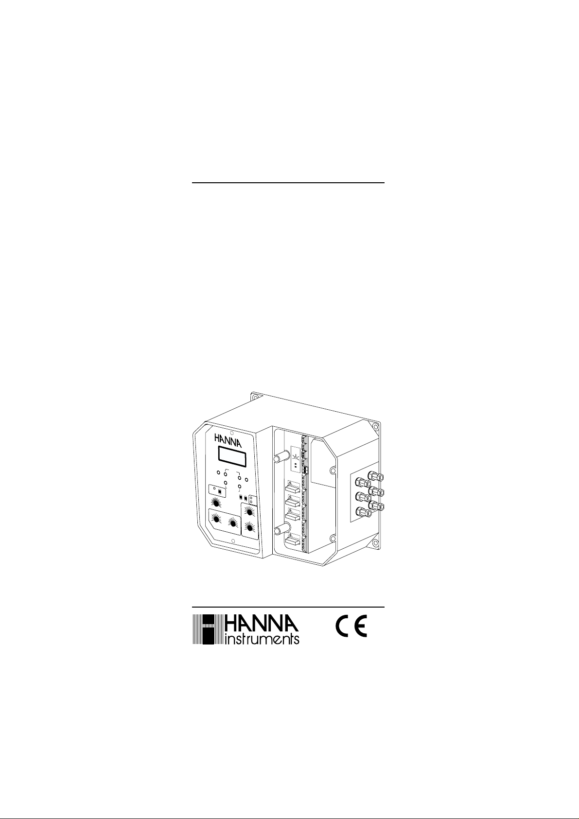
Instruction Manual
HI 9910 - HI 9911
HI 9920
Wall Mounted
pH & ORP
Controllers
H
I 9
pH
O
F
F
S
E
T
O
N
A
L
A
R
M
O
F
F
3
0
2
4
0
0
5
1
0
0
0
6
0
-
1
7
0
8
1
0
.5
1
.
0
p
2
H
P
R
O
P
O
R
9
AC
ID
S
E
T
C
O
A
R
S
E
F
I
N
E
S
L
O
P
E
A
L
K
A
L
I
N
E
S
E
T
S
E
T
AC
ID
AC
ID
R
F
E
E
A
E
D
D
A
L
K
A
L
M
0
0
5
.
0
T
I
O
N
K
T
5
C
2
.5
A
L
°
C
A
K
7
.
5
1
4
5
1
0
5
2
AC
.
5
I
D
7
0
L
S
.5
S
E
C
9
O
0
N
D
S
1
E
T
T
I
N
G
S
M
IN
U
1
0
T
E
S
T
IM
E
R
http://www.hannainst.com
p
H
A
L
A
R
M
1
0
2
T
E
M
P
.C
O
M
M
P
.
T
C
AT
C
4
/
2
0
0
/
2
0
m
A
O
U
T
P
U
T
A
L
A
R
M
S
E
T
A
C
ID
S
E
T
A
L
K
L
I
N
E
Compliance with the CE Directives
These Instruments are in
Page 2

Dear Customer,
Thank you for choosing a Hanna Product.
Please read this instruction manual carefully before using the
instrument. This manual will provide you with the necessary
information for a correct use of the instrument, as well as a more
precise idea of its versatility. If you need more technical information, do not hesitate to e-mail us at tech@hannainst.com.
These instruments are in compliance with the directives
EN 50081-1, 50082-1 and 61010-1.
TABLE OF CONTENTSTABLE OF CONTENTS
TABLE OF CONTENTS
TABLE OF CONTENTSTABLE OF CONTENTS
PRELIMINARY EXAMINATION .....................................................3
GENERAL DESCRIPTION.............................................................3
MECHANICAL LAYOUTS ............................................................. 4
FUNCTIONAL DIAGRAM HI 9910 ............................................... 6
FUNCTIONAL DIAGRAM HI 9911 ............................................... 9
FUNCTIONAL DIAGRAM HI 9920 ............................................. 12
CONNECTIONS & WIRING ....................................................... 14
NORMAL OPERATION & MEASUREMENT ................................... 19
pH CALIBRATION ................................................................... 20
ORP CALIBRATION ................................................................. 22
ADJUSTEMENT OF SETPOINT(S) ............................................... 23
PROPORTIONAL CONTROL ...................................................... 26
OVERDOSAGE TIMER............................................................... 29
pH VALUES AT VARIOUS TEMPERATURES................................. 30
REDOX MEASUREMENT (HI 9920)............................................ 31
ELECTRODE CONDITIONING & MAINTENANCE............................. 33
SUGGESTED INSTALLATIONS FOR pH/ORP ELECTRODES.............. 34
ACCESSORIES......................................................................... 35
WARRANTY ............................................................................ 37
OTHER PRODUCTS FROM HANNA ............................................ 38
CE DECLARATION OF CONFORMITY ........................................... 39
ISO 9000 Certified
Company since 1992
2
Page 3

PRELIMINARY EXAMINATIONPRELIMINARY EXAMINATION
PRELIMINARY EXAMINATION
PRELIMINARY EXAMINATIONPRELIMINARY EXAMINATION
Remove the instrument from the packing material and examine it
carefully to make sure that no damage has occurred during shipping.
If there is any noticeable damage, notify your Dealer.
Note: Save all packing materials until you are sure that the
instrument functions correctly. Any defective item must be
returned in the original packaging together with the supplied
accessories.
IMPORTANT:
1. Read the instructions before using the instrument.
2. The instrument should be connected to a mains socket.
3. Never install the controller outdoors, in a wet or humid area or
under direct sun light. Nor install the controller where liquids may
be sprayed or poured on it.
4. The instrument’s main power line as well as the dosage and
alarm terminals are protected by separate 2A fuses. Use only 2A
fuses for replacement.
GENERAL DESCRIPTIONGENERAL DESCRIPTION
GENERAL DESCRIPTION
GENERAL DESCRIPTIONGENERAL DESCRIPTION
Hanna's wall-mounted pH and ORP controllers
control are designed to meet a variety of process control requirements.
The electrodes can be installed quickly and easily. Simply plug the
universal BNC connector into the socket and twist it into a secured
position. Accurate measurements are displayed on a large LCD.
The controllers come equipped with relays operating at a maximum of
2A (240V).
The Hanna controllers incorporate a triple contact alarm system.
When activated, the alarm contacts will open or close, triggering the
mechanism of your choice, whether a buzzer, light or any other
electrical device.
The recorder output terminals are isolated from the controller circuitry
to avoid any interference and are user-switchable between 0 to 20
mA or 4 to 20 mA.
In order to avoid electrical noise and interference all models provide
for a ground probe (differential input).
These controllers are housed in a rugged, modular, fiber-reinforced
ABS housing.
3
with proportional
Page 4
All models can be wired to work with 110/115V or 220/240V
50/60 Hz power supplies.
The models covered in this manual are:
HI 9910 a single setpoint pH controller
HI 9911 a dual setpoint pH controller, specifically designed for
all those applications in which the pH value intends to
oscillate both up and down
HI 9920 ORP controller, designed for numerous industrial
applications, but in particular for swimming pools and
drinking water sanitation
MECHANICAL LAYOUTSMECHANICAL LAYOUTS
MECHANICAL LAYOUTS
MECHANICAL LAYOUTSMECHANICAL LAYOUTS
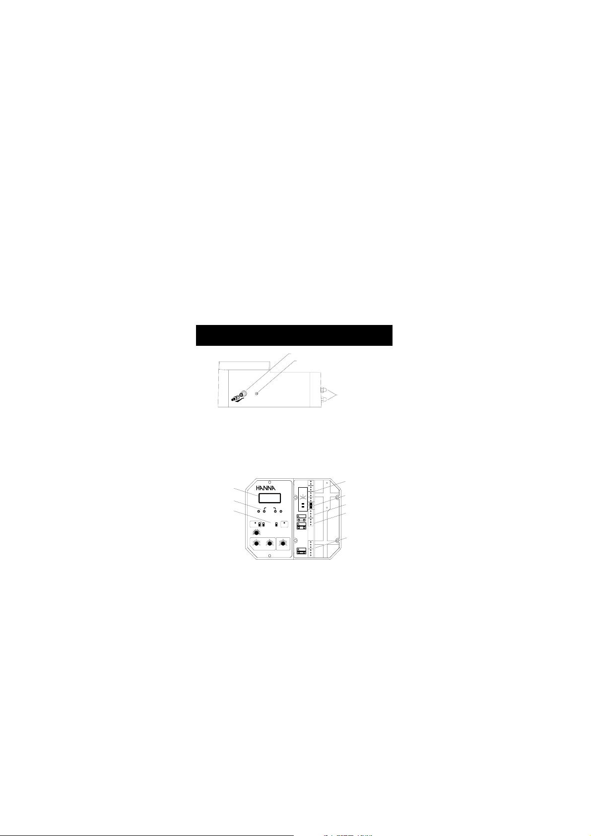
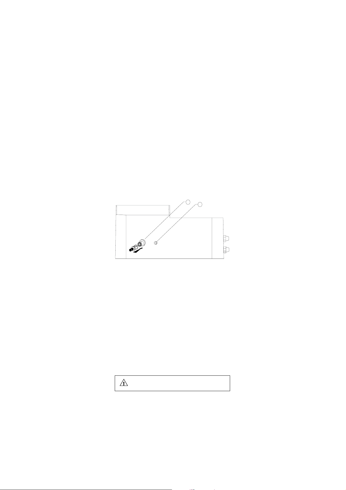
BNC CONNECTOR FOR ELECTRODE
4 mm BANANA SOCKET
FOR GROUND PROBE
WIRING ACCESS
PORTS
Fig. 1
Figure 1: displays the connector for electrode and the wiring access
ports.
LCD DISPLAY
CALIBRATION
TRIMMERS
CONTROL KNOBS
AND SWICHES
pH
ALARM
30
20
10
0
-10
0.511.5
0pH2.0
COARSE
ON
ACID
OFF
ALK
40
50
60
MTC
70
80
PROPORTIONAL SETTINGS
SET POINT
°C
45
090
SECONDS
FINE SLOPEOFFSET
SET
READ
HI 9910
2.557.5
1
MINUTES
ALARM DOSINGTIME
pH
ALARM
1
0
2
TEMP.COMP.
MTC ATC
4/20 0/20
mA OUTPUT
ALARM
SET pH
DOSING
10
LINE
OUTPUT CONTACTS
TEMP.COMPENSATION
SWITCH
ALARM CONTACTS
DOSING TERMINALS
POWER SUPPLY
TERMINALS
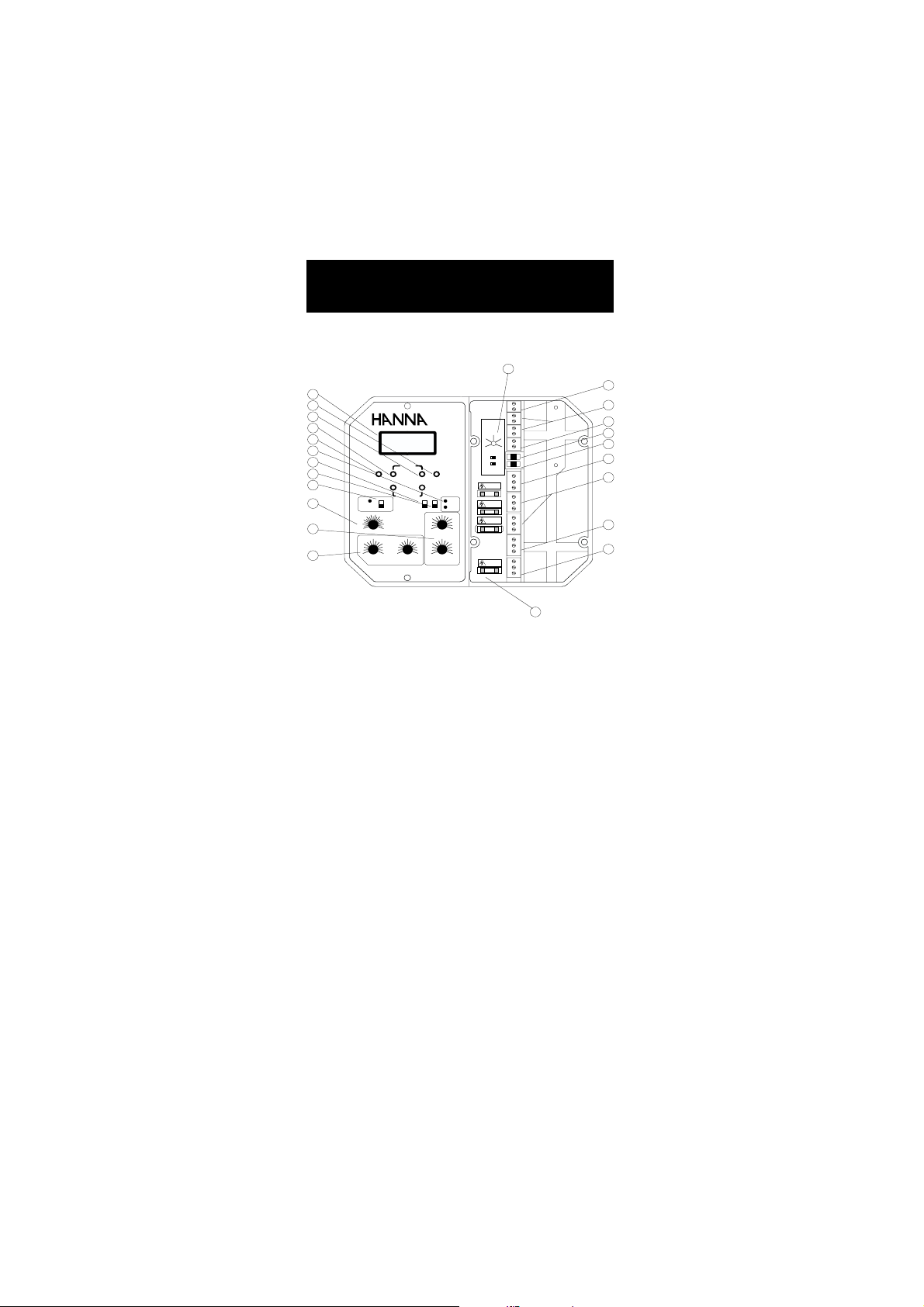
Fig. 2
Figure 2 illustrates the controls and terminals on the HI 9910 pH
controller. Layouts vary from model to model based on their features
and capabilities.
4
Page 5
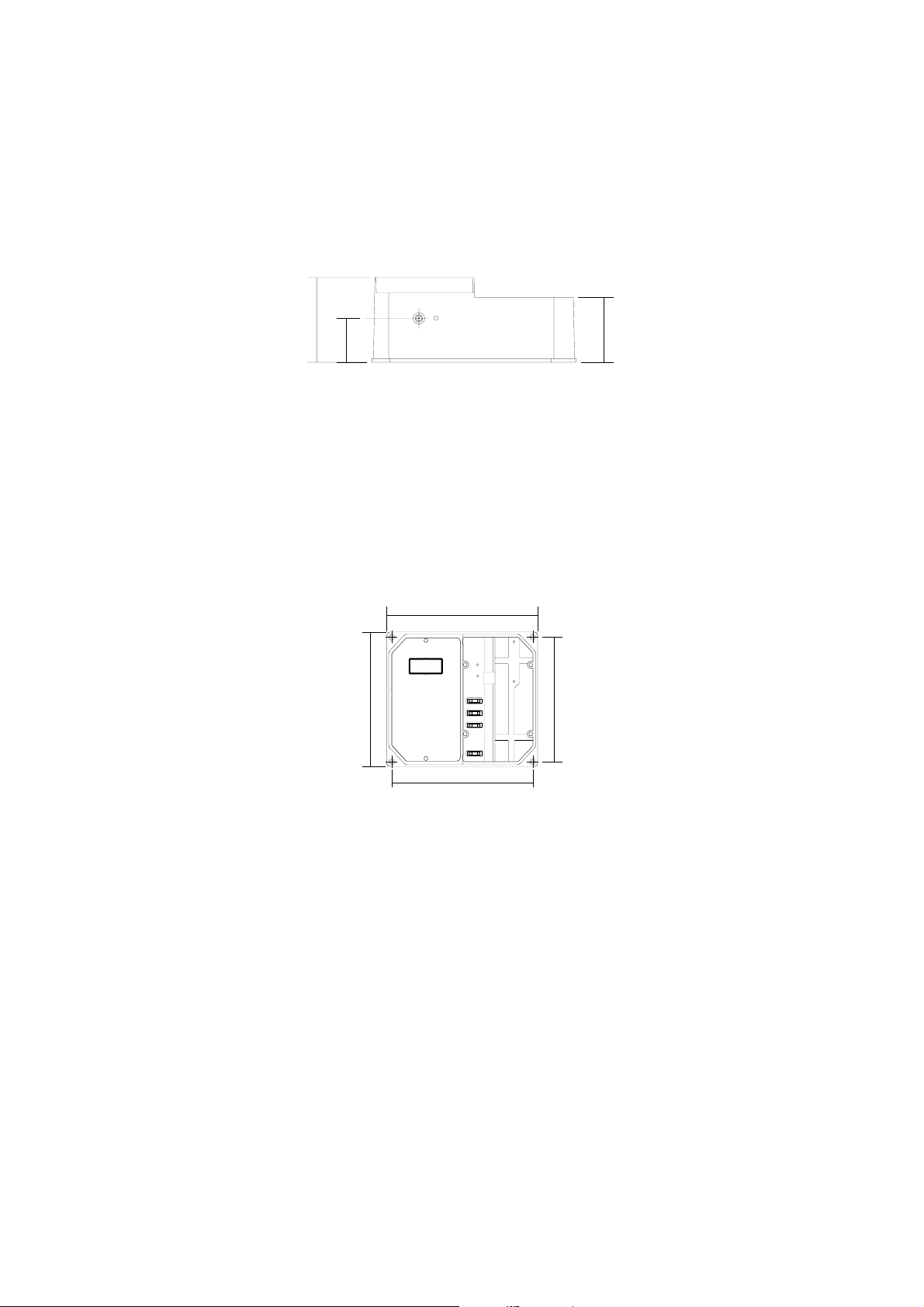
3.8“
96.9 mm
1“
25 mm
75 mm
Fig. 3
Figure 3 is a dimensioned, bottom view of the wall mounted
controllers. The modular design isolates the control circuitry from the
contacts making it possible to make the connections and then close
the compartment. Adjustments can then be made only in the control
area, without having to open the contacts compartment.
227.8 mm
9“
3“
7.4“
188.6 mm
221.8 mm
8.7“
6.9“
174.8 mm
Fig. 4
Figure 4 is a dimensioned front view of the wall mounted controllers.
The molded, mounting holes in the corners provide for quick and
secure installation. No additional hardware is needed for mounting.
All electrical connections and controls are located on the front of the
instrument so that adjustment can be made without having to
remove the unit.
5
Page 6
FUNCTIONAL DIAGRAM HI 9910FUNCTIONAL DIAGRAM HI 9910
FUNCTIONAL DIAGRAM HI 9910
FUNCTIONAL DIAGRAM HI 9910FUNCTIONAL DIAGRAM HI 9910
SINGLE SETPOINT, SINGLE SETPOINT,
SINGLE SETPOINT,
SINGLE SETPOINT, SINGLE SETPOINT,
pp
H CONTROLLERH CONTROLLER
p
H CONTROLLER
pp
H CONTROLLERH CONTROLLER
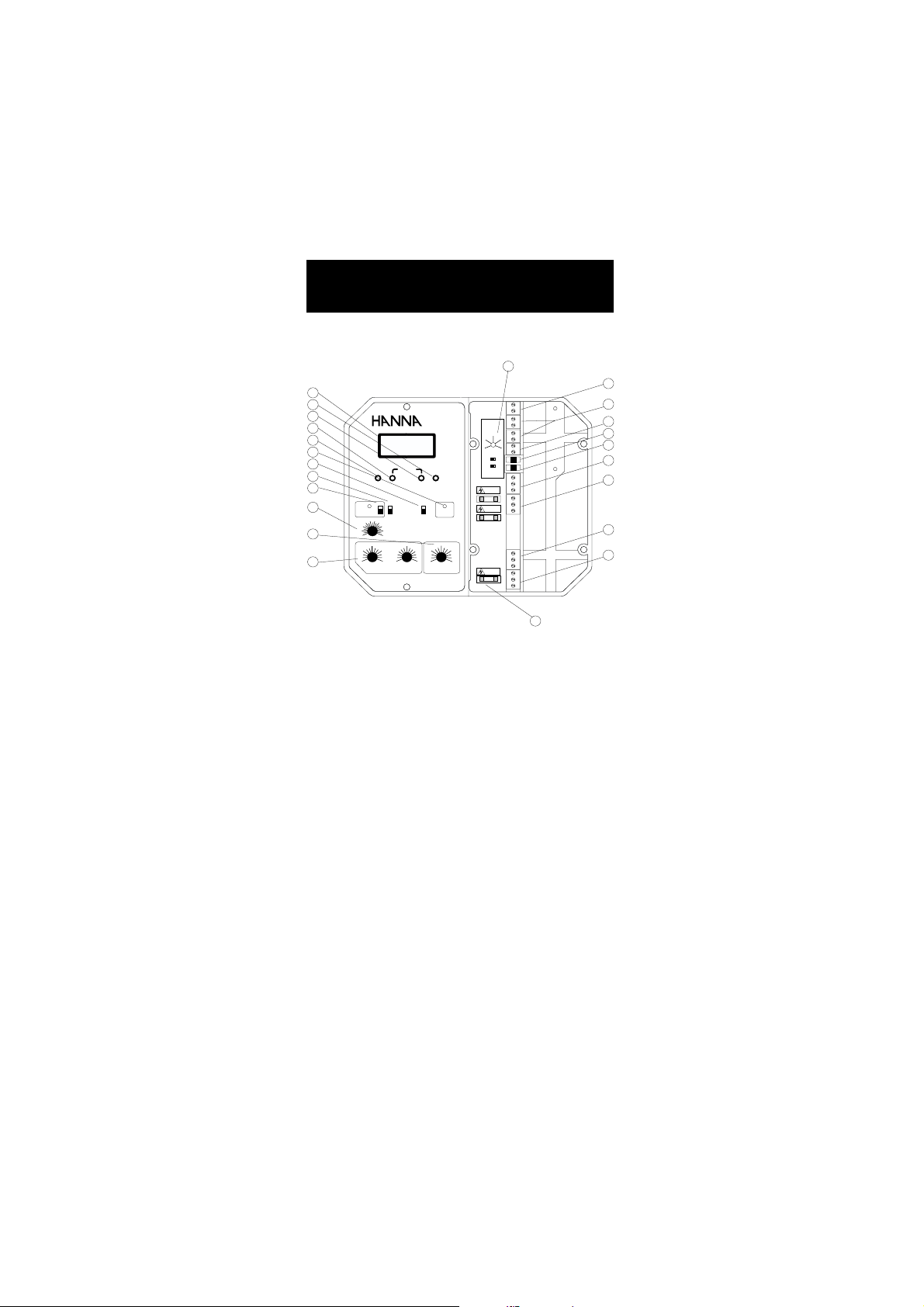
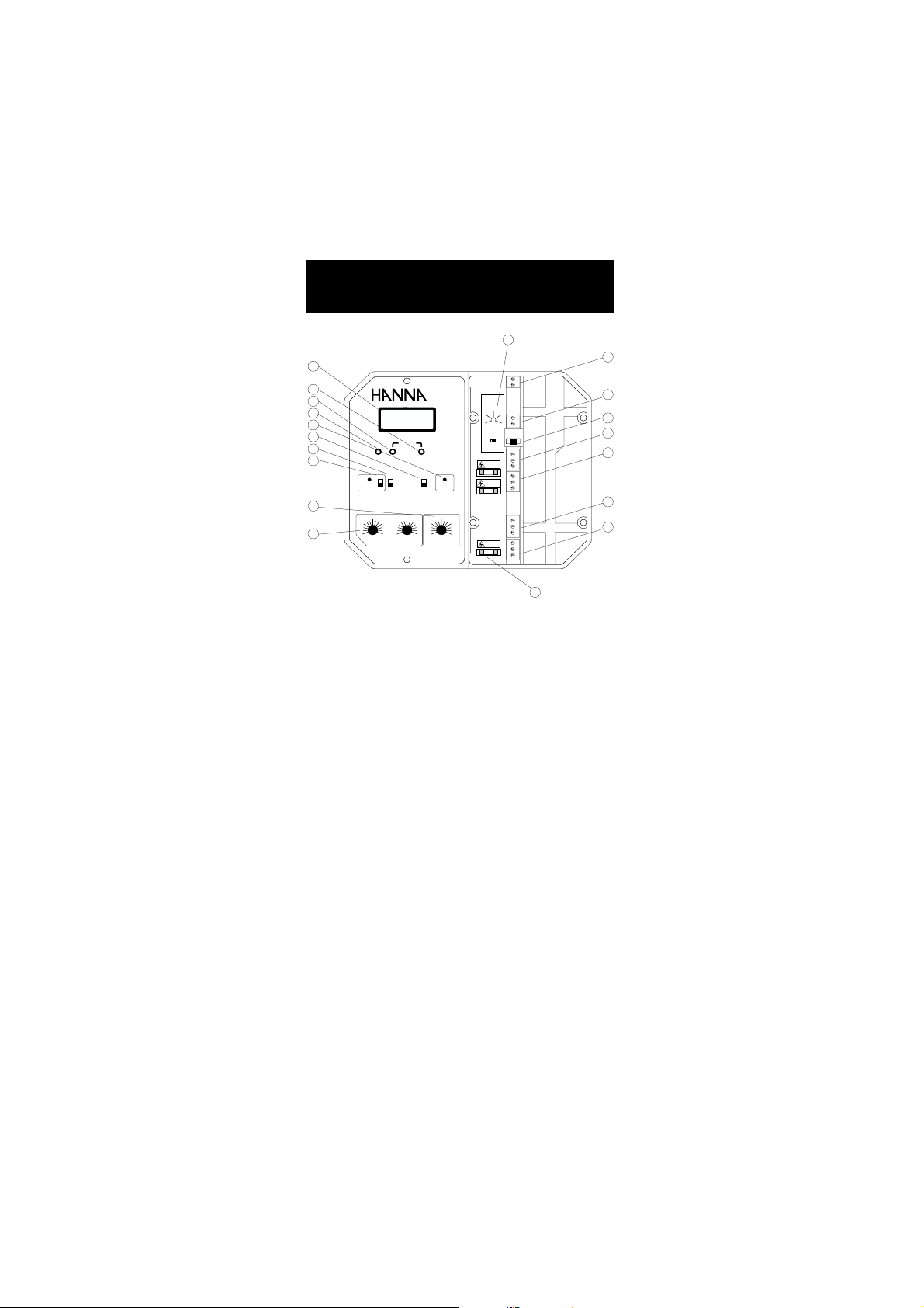
FRONT PANEL
13
1
2
3
4
5
6
7
8
9
10
11
12
pH
ALARM
30
40
20
10
0
-10
0.511.5
0pH2.0
PROPORTIONAL SETTINGS
ON
OFF
50
SET POINT
COARSE
ACID
ALK
60
MTC
70
°C
80
45
090
SECONDS
HI 9910
FINE SLOPEOFFSET
SET
READ
2.557.5
ALARM DOSINGTIME
DOSING
1
MINUTES
pH
ALARM
1
0
2
TEMP.COMP.
MTC ATC
4/20 0/20
mA OUTPUT
ALARM
SET pH
10
LINE
23
Left panel
1. Liquid Crystal Display
2. Slope calibration trimmer
3. Fine setpoint trimmer
4. Coarse setpoint trimmer
5. Offset calibration trimmer
6. Dosing LED visual signal
7. READ for actual measurement and SET for setpoint
adjustment
8. Acid or Alkaline Dosage selection
9. Alarm LED and switch to disable the alarm
10. Graded dial for Manual Temperature Compensation
11. Overdosage timer
12. Proportional pH band and time cycle settings
14
15
16
17
18
19
20
21
22
Right panel
13. pH alarm setting from 0 to 2 pH
14. Short the terminals if a ground probe is not in use, or
connect the ground probe wire to the Matching Pin terminal
15. Three-wire Pt 100 plus a shield protection
6
Page 7
16. Recorder output contacts
17. Automatic or Manual Temperature Compensation switch
18. 0 to 20 or 4 to 20 mA isolated output switch
19. Triple contact alarm in a Normally Closed (NC) or a Normally
Open (NO) position.
20. Powered dosage terminals (Relay)
21. 110/115V or 220/240V power configuration
22. Incoming power terminals
23. Fuses
BOTTOM VIEW
24
25
24. Female BNC socket for combination pH electrode
25. 4-mm Banana socket for ground probe
Unplug the instrument from the power supply before
wiring and replacing the fuses.
7
Page 8

Specifications HI 9910
RANGE 0.00 to 14.00 pH
RESOLUTION 0.01 pH
ACCURACY ±0.02 pH
(@20°C/68°F)
TYPICAL EMC ±0.1 pH
DEVIATION
mA OUTPUT User-selectable 0 to 20 mA or 4 to 20 mA
CALIBRATION Through "OFFSET" and "SLOPE" trimmers
TEMPERATURE
COMPENSATION
SETPOINT From 0.00 to 14.00 pH with "COARSE" and "FINE"
RANGE trimmers with "ACID" or "ALK" (alkaline) selection
PROPORTIONAL pH is user adjustable from 0.0 to 2.0 and
CONTROL time cycle from 0 to 90 seconds
ALARM
CONTACT
DOSING TERMINALS Relay terminals (115 to 240V, Max.2A,1,000,000
strokes) are activated when pH exceeds the setpoint with
“ACID” dosage or falls below the setpoint with “ALK”
selection (Alkaline dosage)
POWER SUPPLY 220/240V or110/115V at 50/60Hz
ENVIRONMENT -10 to 50 °C (14 to 122 °F)
WEIGHT 1.6 Kg (3.5 lb.)
ENCLOSURE 181 x 221 x 142mm (7.1 x 8.7 x 5.6")
CASE MATERIAL Fiber-reinforced, self-extinguishing ABS
over the 0-14 pH range with isolated output
(Max. ±1.5 pH for offset and 80% to 110% for slope)
Manual from -10 to 80 °C (14 to 176 °F) or
automatic with a 3-wire Pt 100 probe from 0 to 50
°C (32 to 122 °F)
Terminals can be configured as normally open or
normally closed (isolated output Max. 2A, Max. 240V,
resistive load, 1,000,000 strokes). The alarm is
activated if pH varies by more than user-selectable
interval (0 to 2 pH) from setpoint or due to overdosage
max. 95% RH non-condensing
8
Page 9
FUNCTIONAL DIAGRAM HI 9911FUNCTIONAL DIAGRAM HI 9911
FUNCTIONAL DIAGRAM HI 9911
FUNCTIONAL DIAGRAM HI 9911FUNCTIONAL DIAGRAM HI 9911
DUAL SETPOINT, DUAL SETPOINT,
DUAL SETPOINT,
DUAL SETPOINT, DUAL SETPOINT,
pHpH
CONTROLLER CONTROLLER
pH
CONTROLLER
pHpH
CONTROLLER CONTROLLER
FRONT PANEL
13
1
2
3
4
5
6
7
8
9
10
11
12
pH
ALARM
30
20
10
0
-10 80
1
0.5
0
pH
PROPORTIONAL SETTINGS
ON
OFF
40
50
60
70
1.5
2.0 0
HI 9911
ACID SET
COARSE FINE SLOPEOFFSET
ALKALINE SET
SET
ACID
READ
ALK
2.557.5
MTC
°C
1
45
2.557.5
90
1
SECONDS
MINUTES
TIMER
pH
ALARM
1
0
2
TEMP.COMP.
MTC ATC
4/20 0/20
mA OUTPUT
ALARM
ACID
SET ACID
FEED
ALK
ALK
SET ALK
10
ACID
10
LINE
23
Left panel
1. Liquid Crystal Display
2. Slope calibration trimmer
3. Fine setpoint trimmers for acid and alkaline feed
4. Coarse setpoint trimmers for acid and alkaline feed
5. Offset calibration trimmer
6. Dosing LED signals for acid and alkaline feed
7. READ for actual measurement and SET for setpoint
adjustment
8. Acid or Alkaline selection for setpoint
9. Alarm LED and switch to disable the alarm
10. Graded dial for Manual Temperature Compensation
11. Two independent overdosage timers
12. Proportional pH band and time cycle settings
14
15
16
17
18
19
20
21
22
Right panel
13. pH alarm setting from 0 to 2 pH
14. Short the terminals if a ground probe is not in use, or
connect the ground probe wire to the Matching Pin terminal
15. Three-wire Pt 100 plus a shield protection
16. Recorder output contacts
17. Automatic or Manual Temperature Compensation switch
9
Page 10
18. 0 to 20 or 4 to 20 mA isolated output switch
19. Triple contact alarm in a Normally Closed (NC) or a Normally
Open (NO) position.
20. Powered dosage terminals (Relays)
21. 110/115V or 220/240V power configuration
22. Incoming power terminals
23. Fuses
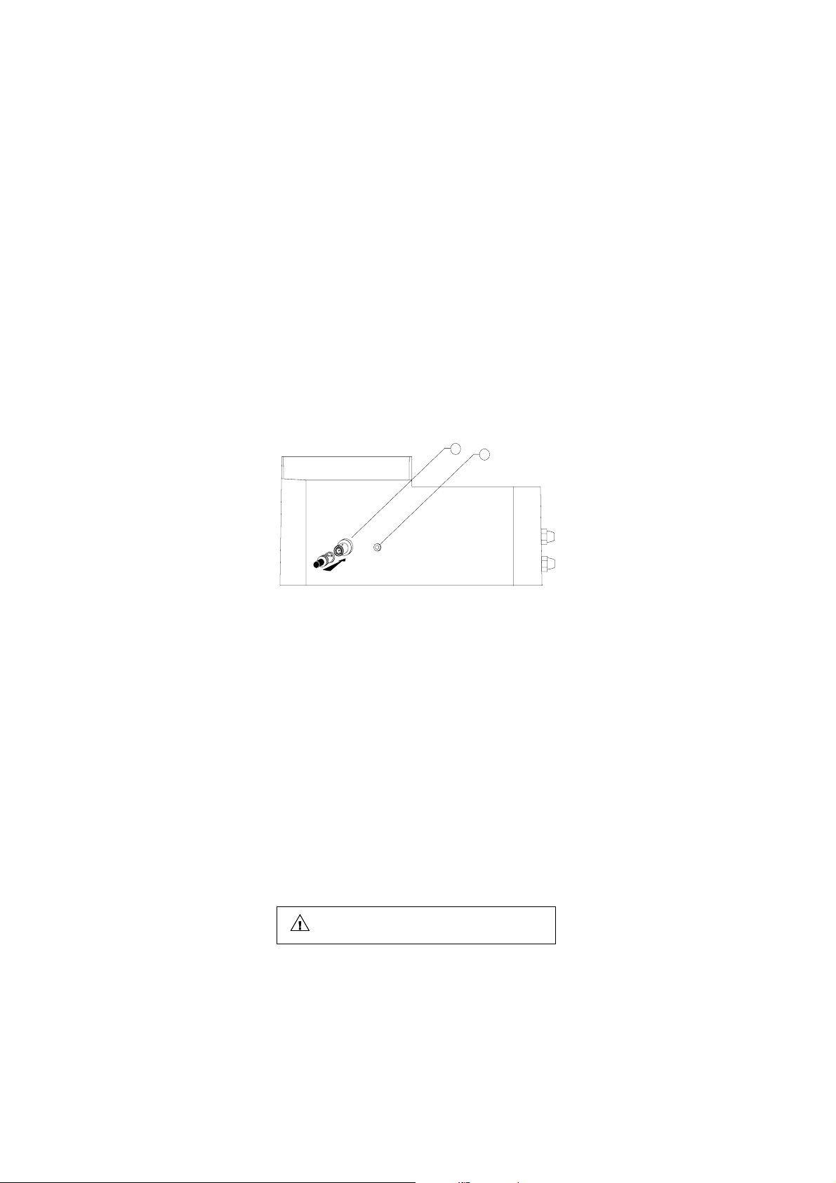
BOTTOM CONNECTION
24
25
24. Female BNC socket for combination pH electrode
25. 4-mm Banana socket for ground probe
Unplug the instrument from the power supply before
wiring and replacing the fuses.
10
Page 11

Specifications HI 9911
RANGE 0.00 to 14.00 pH
RESOLUTION 0.01 pH
ACCURACY ±0.02 pH
(@20°C/68°F)
TYPICAL EMC ±0.1 pH
DEVIATION
mA OUTPUT User-selectable 0 to 20 mA or 4 to 20 mA
CALIBRATION Through "OFFSET" and "SLOPE" trimmers
TEMPERATURE
COMPENSATION
SETPOINT
RANGE
PROPORTIONAL pH is user adjustable from 0.0 to 2.0 and
CONTROL time cycle from 0 to 90 seconds
ALARM
CONTACT
DOSING TERMINALS Two sets of independent relay terminals (115 to 240V,
Max.2A, 1,000,000 strokes) are activated whenever pH
exceeds the “ACID” setpoint or falls below the “ALK”
setpoint (Alkaline dosage)
POWER SUPPLY 220/240V or110/115V at 50/60Hz
ENVIRONMENT -10 to 50 °C (14 to 122 °F)
WEIGHT 1.6 Kg (3.5 lb.)
ENCLOSURE 181 x 221 x 142mm (7.1 x 8.7 x 5.6")
CASE MATERIAL Fiber-reinforced, self-extinguishing ABS
over the 0-14 pH range with isolated output
(Max. ±1.5 pH for offset and 80% to 110% for slope)
Manual from -10 to 80 °C (14 to 176 °F) or automatic
with 3-wire Pt 100 probe from 0 to 50 °C (32 to 122 °F)
From 0.00 to 14.00 pH with 2 trimmers: "COARSE"
for approx. regulation, "FINE" for fine tuning.
Terminals can be configured as normally open or
normally closed (isolated output Max. 2A, Max.
240V, resistive load, 1,000,000 strokes). The alarm
is activated if pH varies by more than user-selectable
interval (0 to 2 pH) from setpoint or due to
overdosage
max. 95% RH non-condensing
11
Page 12
FUNCTIONAL DIAGRAM HI 9920FUNCTIONAL DIAGRAM HI 9920
FUNCTIONAL DIAGRAM HI 9920
FUNCTIONAL DIAGRAM HI 9920FUNCTIONAL DIAGRAM HI 9920
ORP CONTROLLER ORP CONTROLLER
ORP CONTROLLER
ORP CONTROLLER ORP CONTROLLER
FRONT PANEL
13
1
3
4
5
ORP
6
7
8
9
11
12
mV
ALARM
50
0
mV
PROPORTIONAL SETTINGS
ON
OFF
150
200
HI 9920
SET POINT
COARSE FINECAL
SET
OXID
RED
DOSING
READ
45100
2.557.5
1
0
90
MINUTES
SECONDS
TIMER
mV
ALARM
100
0
200
mA OUTPUT
4/20 0/20
ALARM
SET mV
10
LINE
Left panel
1. Liquid Crystal Display
3. Fine setpoint trimmer
4. Coarse setpoint trimmer
5. Calibration trimmer
6. Dosing LED visual signal
7. READ for actual measurement and SET for setpoint
adjustment
8. Oxidization or Reduction Dosage selection
9. Alarm LED and switch to disable the alarm
11. Overdosage timer
12. Proportional ORP band and time cycle settings
14
16
18
19
20
21
22
23
Right panel
13. ORP alarm setting from 0 to 200 mV
14. Short the terminals if a ground probe is not in use, or
connect the ground probe wire to the Matching Pin terminal
16. Recorder output contacts
18. 0 to 20 or 4 to 20 mA isolated output switch
19. Triple contact alarm in a normally-closed (NC) or a normally
open (NO) position.
12
Page 13

20. Powered dosage terminals (Relay)
21. 110/115V or 220/240V power configuration
22. Incoming power terminals
23. Fuses
BOTTOM CONNECTION
24
25
24. Female BNC socket for combination ORP electrode
25. 4-mm Banana socket for ground probe
Unplug the instrument from the power supply before
wiring and replacing the fuses.
13
Page 14

Specifications HI 9920
RANGE -500 to 1500 mV
RESOLUTION 1 mV
ACCURACY ±5mV
(@20°C/68°F)
TYPICAL EMC ±6 mV
DEVIATION
mA OUTPUT User-selectable 0 to 20 mA or 4 to 20 mA
CALIBRATION Through "CAL" trimmer
SETPOINT
From -500 to 1500 mV with "COARSE" and "FINE"
RANGE 2 trimmers with "OXID" or "RED" selection for oxidizing
or reducing dosage
PROPORTIONAL ORP setting is adjustable from 0 to 200 mV and
CONTROL time cycle from 0 to 90 seconds
ALARM
CONTACT
DOSING TERMINALS Relay terminals (115 to 240V, Max.2A,1,000,000
strokes) are activated when mV exceeds the setpoint
with “RED” dosage or when mV falls below the
setpoint with “OXID” selection
POWER SUPPLY 220/240V or110/115V at 50/60Hz
ENVIRONMENT -10 to 50 °C (14 to 122 °F)
WEIGHT 1.6 Kg (3.5 lb.)
ENCLOSURE 181 x 221 x 142mm (7.1 x 8.7 x 5.6")
CASE MATERIAL Fiber-reinforced, self-extinguishing ABS
over the -500 to 1500 mV range with isolated output
Normally open or normally closed isolated outputs
(Max. 2A, Max. 240V, resistive load, 1,000,000 strokes).
Terminals are activated when the ORP value varies by
more than the user selectable interval (0 to 200mV)
from setpoint, or due to overdosage
max. 95% RH non-condensing
CONECTIONS & WIRINGCONECTIONS & WIRING
CONECTIONS & WIRING
CONECTIONS & WIRINGCONECTIONS & WIRING
GENERAL POINTS
relay terminalsrelay terminals
• The
relay terminals of the controllers are
relay terminalsrelay terminals
means that you can simply hook up your pumps or electrovalves
directly to the controller and do not need additional power
supply.
• Unscrew the 4 screws on the right hand panel and remove the
cover and the gasket. Thread the wires through the access ports
on the right hand side of the controller.
14
poweredpowered
powered. This
poweredpowered
Page 15

BeforeBefore
•
connecting the controller to the mains, wire connecting the controller to the mains, wire
Before
connecting the controller to the mains, wire
BeforeBefore
connecting the controller to the mains, wire connecting the controller to the mains, wire
the controller completelythe controller completely
the controller completely and make all the connections for
the controller completelythe controller completely
pumps, alarm, electrode, set the alarm threshold and adjust the
settings. Upon completion,
replace the coverreplace the cover
replace the cover.
replace the coverreplace the cover
Only then
connect the controller to the power supply.
ELECTRODE & GROUND PROBE CONNECTIONS
ELECTRODE WITH
BNC CONNECTION
MATCHING PIN FOR GROUND PROBE
WIRING ACCESS
PORTS
• Simply attach any combination pH or ORP electrode with a
male BNC connector (such as HI 1002/3 or HI 2002/3) to the
female BNC socket located on the bottom of the casing and twist
it into a secure position.
• All models provide for a Ground Probe (differential input) to
reduce electrical noise and interference. The
controllers are shipped with the Matching Pin
and Reference terminals shorted (see 14 - Functional Diagram). If you are not using a matching
pin (ground probe),
the next two paragraphs.
• It is recommended that only electrodes that incorporate a matching pin (such as HI 1003/3 or HI 2003/3) are utilized. In this
case simply
matching pin to the socketmatching pin to the socket
matching pin to the socket located next to the BNC
matching pin to the socketmatching pin to the socket
connector on the outer casing (see 25 - Functional Diagram) and
remove the jumperremove the jumper
remove the jumper shorting the matching pin terminals.
remove the jumperremove the jumper
• When using a separate probe for grounding purposes, wire it to
the Matching Pin terminal on the right hand panel and
the jumperthe jumper
the jumper (see 14 Functional Diagram).
the jumperthe jumper
leave the terminals shortedleave the terminals shorted
leave the terminals shorted and skip
leave the terminals shortedleave the terminals shorted
attach the 4-mm banana connector of theattach the 4-mm banana connector of the
attach the 4-mm banana connector of the
attach the 4-mm banana connector of theattach the 4-mm banana connector of the
removeremove
remove
removeremove
NOTE:
NEVER leave the jumper in when
using an electrode with a matching
pin. This can shorten the life of the
electrode (reference) drastically.
15
REMOVE WHEN
USING MATCHING PIN
Page 16

RELAY CONNECTIONS
• Wire the external device or devices (pumps or electrovalves)
directly to the relay terminal strip of the controller (see 20 Functional Diagram). The
do not need an external power supplydo not need an external power supply
you
do not need an external power supply for the pump
do not need an external power supplydo not need an external power supply
terminals are poweredterminals are powered
terminals are powered and hence
terminals are poweredterminals are powered
or electrovalve. There is one terminal strip for HI 9910 and
HI 9920 and two for HI 9911.
BL DOSING PUMP
pH
20
10
0
-10
0.511.5
0pH2.0
ON
ALARM
OFF
30
40
PROPORTIONAL SETTINGS
COARSE
ACID
ALK
50
60
MTC
70
80
SET POINT
°C
45
090
SECONDS
pH
HI 9910
ALARM
1
0
2
TEMP.COMP.
MTC ATC
4/20 0/20
mA OUTPUT
FINE SLOPEOFFSET
ALARM
SET
SET pH
DOSING
READ
2.557.5
10
1
MINUTES
ALARM DOSINGTIME
LINE
ALARM CONNECTIONS
• The operator can select an alarm threshold of 0.0
to 2.0 pH for HI 9910 and HI 9911 or 0 to 200
mV for HI 9920 by turning the alarm knob (see 13
of Functional Diagram). If the actual measurements
are above or below the setpoint by a margin
greater than the user-selectable alarm threshold,
the alarm terminal is activated. The alarm can be
selected as normally closed ("NC") by connecting the external
device to the C and NC terminals or normally open ("NO") by
connecting the external device to the C and NO terminals.
• When activated, the alarm contacts will open or close, triggering
the mechanism of your choice. When the
all other terminalsall other terminals
all other terminals (such as dosing relay etc.)
all other terminalsall other terminals
disactivateddisactivated
disactivated. The alarm LED light also comes on.
disactivateddisactivated
alarm is activatedalarm is activated
alarm is activated
alarm is activatedalarm is activated
pH
ALARM
1
0
TEMP. COMP.
MTC ATC
4/20 0/20
mA OUTPUT
areare
are
areare
2
10
0
-10
0.511.5
0pH2.0
pH
ALARM
20
ON
OFF
30
40
50
60
PROPORTIONAL SETTINGS
SET POINT
COARSE
ACID
ALK
MTC
70
°C
80
090
SECONDS
pH
HI 9910
ALARM
1
0
2
TEMP.COMP.
MTC ATC
4/20 0/20
mA OUTPUT
FINE SLOPEOFFSET
ALARM
SET
SET pH
DOSING
READ
45
2.557.5
10
1
MINUTES
ALARM DOSINGTIME
LINE
EXTERNAL ELECTRICAL
DEVICE ACTIVATED BY
AN ALARM CONDITION
16
Page 17

ALARM
ON
OFF
• The alarm ON/OFF switch is only to
ALARM DOSING TIME
MINUTES
1
10
2.5
5
7.5
the alarm terminalthe alarm terminal
the alarm terminal (e.g. the buzzer will
the alarm terminalthe alarm terminal
disabledisable
disable
disabledisable
not sound). However, all other functions such as
disactivation of the dosing relay remain unvaried, i.e. the pump
ceases to dose until the alarm condition is alleviated.
• The controllers provide for
automatic fail-safeautomatic fail-safe
automatic fail-safe security by
automatic fail-safeautomatic fail-safe
activating the alarm if there is a power failure, regardless of
whether the NC or NO configurations were chosen.
• The alarm is also activated if the maximum
dosage time is exceeded. The overdosage timer
can be set from 1 to 10 minutes. For HI 9911,
two timers for acid and alkaline corrections can
be independently selected.
• Once in an alarm condition, the alarm contact remains activated
until the switch is manually put in the off position or the
measurements returns to normal values.
Model Alarm is activated when the reading varies by :
HI 9910 0 to 2.0 pH (selectable) above or below the setpoint
HI 9911 0 to 2.0 pH (selectable) lower than the ALKALINE setpoint or
higher than the ACID setpoint
HI 9920 0 to 200 mV (selectable) above or below the setpoint
RECORDER OUTPUT CONNECTIONS
• The recorder output contacts are
isolatedisolated
isolated from the controller circuitry
isolatedisolated
to avoid interference. Select between
0 to 20 or 4 to 20 mA with the
Output mA
selector
selector (see 18 - Functional Diagram) before wiring. The output
mA value is proportional and is the pH or ORP value over the
entire range. For example, when measuring pH 7, the output
values are 10 mA or 12 mA based on whether the 0-20 or 4-20
output were respectively selected.
RECORDER
pH
ALARM
30
20
10
0
-10
0.511.5
0pH2.0
PROPORTIONAL SETTINGS
ON
OFF
40
50
SET POINT
COARSE
ACID
ALK
60
MTC
70
°C
80
090
SECONDS
pH
HI 9910
ALARM
1
0
2
TEMP.COMP.
MTC ATC
4/20 0/20
mA OUTPUT
FINE SLOPEOFFSET
READ
45
SET
2.557.5
1
ALARM DOSINGTIME
ALARM
SET pH
DOSING
10
MINUTES
LINE
17
0/204/20
Page 18

TEMPERATURE COMPENSATION
Neutral
Line
POWER
SUPPLY
220 VAC
Configuration
L
L1
N1
Neutral
Line
POWER
SUPPLY
L
L1
N1
110 VAC
Configuration
110 VAC
Configuration
(HI 9910 and HI 9911 only)
• Manual Temperature Compensation:
the MTC position (see 17-Functional Diagram). Then manually set
the temperature by turning the dial (see 10 - Functional
Diagram) to the correct working temperature.
ATCMTC
Temp. compensation
selector
• Automatic Temperature Compensation:
the ATC position (see 17-Functional Diagram). Then wire a Pt
100 probe such as HI 5001/5 to the controller’s terminals as
shown.
Pt 100 1-grey
Pt 100 2-brown
Pt 100 3-yellow
Pt 100 shield
1-grey
2-brown
3-yellow
shield
HI 5001/5 is made of stainless steel. For solutions
not compatible with stainless steel, use the glassbody HI 5002/5 or other appropriate 3-wire Pt
100 probe.
Move the selector to
30
40
20
10
0
-10
50
Move the selector to
1
2
3
MAIN POWER SUPPLY CONNECTION
BeforeBefore
•
connecting the unit to the mains connecting the unit to the mains
Before
connecting the unit to the mains, make sure
BeforeBefore
connecting the unit to the mains connecting the unit to the mains
that the
controller is completely wiredcontroller is completely wired
controller is completely wired and that all
controller is completely wiredcontroller is completely wired
connections for pump, alarm, electrode, etc. have been made.
60
MTC
70
°C
80
• For 220-240V, short the L1 and N1 terminals. Then wire the external power supply
to the three terminals as shown.
• For 110-115V, short the L and L1 terminals
and
the N1 and Neutral. Then wire
the external power supply to the three
terminals as shown.
• Replace the cover with the gasket and screw it tight with the 4
screws provided.
Only thenOnly then
Only then connect the controller to the mains.
Only thenOnly then
18
Page 19

NORMAL OPERATION andNORMAL OPERATION and
ATCMTC
NORMAL OPERATION and
NORMAL OPERATION andNORMAL OPERATION and
MEASUREMENTMEASUREMENT
MEASUREMENT
MEASUREMENTMEASUREMENT
Make sure that the controller has been properly calibrated before
commencing and that the pH or ORP setpoint(s) have been adjusted
(see the following pages).
The pH or ORP electrodes and any ground probes must be properly
connected and wired to the controller (see preceding pages). Remove
the protecteive cap if it is still on the tip of the electrode.
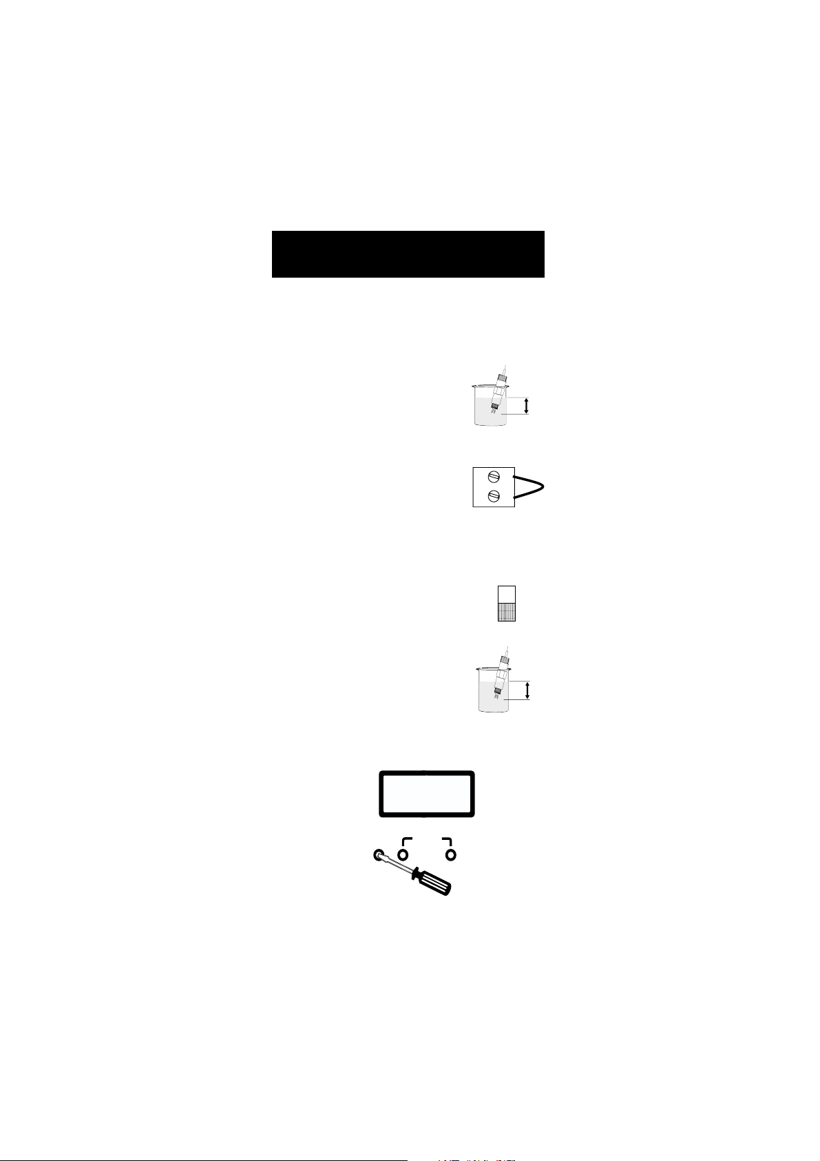
Ensure that the electrode is properly installed and lies perma-
SET
nently in the solution to a depth of at least 4cm/1.5”. The
selector (see 7 - Functional Diagram) must be on the "READ"
READ
position.
If temperature compensation is necessary (HI 9910 and HI 9911),
make sure that the temperature probe is also immersed in the
solution and the selector is on ATC (see 17 - Functional Diagram).
For manual temperature compensation, the selector should be on MTC with the dial showing
the temperature of the solution.
30
40
50
20
ATCMTC
10
0
-10
60
MTC
70
°C
80
The actual pH or ORP value of the solution will be displayed on the
LCD.
SET
8.00
READ
All controllers provide for a visual dosing status
through an LED. With HI 9910 and HI 9920 the
DOSING LED lights up when the controller is in the
pH or ORP dosage mode and the terminals are
activated.
Likewise, HI 9911 provides for two LED’s, one for
ACID and another for ALK (alkaline) dosage when
the appropriate terminals are activated.
19
DOSING
ACID
FEED
ALK
Page 20

pH pH
4cm
(1½")
HI 7007
CALIBRATIONCALIBRATION
pH
CALIBRATION
pH pH
CALIBRATIONCALIBRATION
(HI 9910 and HI 9911)
Make sure that the pH electrode and any ground probe have been
properly connected and wired to the controller (see preceding pages)
and that the meter is plugged to the mains.
Calibration should be ideally performed at a temperature similar to
that of the liquid to be monitored.
Use a Checktemp (or an accurate thermometer)
as reference for temperature compensation.
Remove the electrode cap if it is still on the
electrode.
During calibration, move the electrode and the
separate ground probe (if in use) together from
one buffer to the next.
If no separate ground probe is being used, make sure
that the Reference and the Matching Pin terminals are
shorted (see 14 - Functional Diagram).
If the electrode incorporates a ground probe/matching pin (HI 1003/3)
then remove the jumper.
• Turn the switch to the "READ" position.
HI 7007
HI 7007
SET
(1½")
(1½")
4cm
4cm
READ
OFFSET ADJUSTMENT:
• Rinse the tip of the electrode with pH
7.01 solution (HI7007), then dip the
bottom 4 cm (1.5”) of the electrode (and
ground probe) in the pH 7.01 buffer.
• Place the Checktemp thermometer in the buffer solution. Turn the
dial (see 10 - Functional Diagram) to show the same temperature
30
40
50
60
MTC
70
°C
80
ATCMTC
Temp. compensation
selector
20
10
0
-10
20
Page 21

as that on the Checktemp and make sure the selector is in the
MTC position (see 17 - Functional Diagram).
• Wait for the measurement to stabilize and then adjust the
"OFFSET" trimmer to display pH
7.01 on the LCD if the tempera-
pH
7.01
ture of the buffer solution is at
25°C (77°F).
• If the temperature of the buffer
COARSE
SET POINT
FINE SLOPEOFFSET
solution is not 25°C (77°F),
refer to the chart at the end of the manual for the appropriate
buffer value at a given temperature and adjust the trimmer
accordingly.
SLOPE ADJUSTMENT:
• Rinse the electrode (and ground probe)
thoroughly with water and immerse the
bottom 4 cm (1.5”) in a pH 4.01
(HI 7004) or a pH 10.01 (HI 7010)
buffer solution.
HI 7004
Note: Use pH 4.01 if you are going to be monitoring acidic solutions
or pH 10.01 for alkaline samples.
• Stir the electrode and wait for the display to stabilize before
adjusting the "SLOPE" trimmer to display pH 4.01 (or 10.01) on
the LCD if the temperature of the buffer solution is at 25 °C
(77 °F). Otherwise, refer to the
chart at the end
pH
4.01
of the manual
COARSE
SET POINT
FINE SLOPEOFFSET
for the appropriate buffer value
and adjust the
trimmer accordingly.
The pH calibration is now complete.
(1½")
4cm
21
Page 22
ORP CALIBRATIONORP CALIBRATION
4cm
(1½")
HI 7020
4cm
(1½")
HI 7020
ORP CALIBRATION
ORP CALIBRATIONORP CALIBRATION
(HI 9920)
Make sure that the ORP electrode and any ground probe have been
properly connected and wired to the controller (see preceding pages)
and that the meter is plugged to the mains.
Remove the electrode cap if it is still on the electrode.
During calibration, introduce both the electrode
and the ground probe (if in use) to the known
solution. An immersion level of 4 cm (1.5”) is
recommended.
If no separate ground probe is being used, make sure that the
Reference and the Matching Pin terminals are
shorted (see 14 - Functional Diagram).
If the electrode incorporates a ground probe/matching pin (HI 2003/3)
then remove the jumper.
SET
• Turn the switch to the "READ" position.
READ
• Immerse the electrode in a HI 7020
(or
another known) ORP solution and wait for
a few minutes for the reading to stabilize.
• Adjust the CAL trimmer to 230 ±20 mV (or a known value).
ORP
mV
230
SET POINT
COARSE FINECAL
22
Page 23

ADJUSTEMENT OF SETPOINT(S)ADJUSTEMENT OF SETPOINT(S)
ADJUSTEMENT OF SETPOINT(S)
ADJUSTEMENT OF SETPOINT(S)ADJUSTEMENT OF SETPOINT(S)
Make sure that the electrode (and any ground probe) is properly
installed and calibrated (see the preceding pages).
FOR HI 9910
Turn the switch to the "SET" position (see 7 - Functional Diagram).
The display will show the previously adjusted value (e.g. pH 8.00).
SET
8.00
READ
Using a small screwdriver, first adjust the setpoint through the
COARSE trimmer and then fine tune it to your required level with the
FINE trimmer (see 3 and 4 - Functional Diagram) until the desired
set value is displayed (e.g. pH 6.00).
pH
6.18
SET POINT
FINE SLOPEOFFSET
COARSE
pH
6.00
SET POINT
FINE SLOPEOFFSET
COARSE
DOSING DIRECTION
Select the direction of dosing through the "ACID"/”ALK” switch (see 8
- Functional Diagram). In order to dose acidic substances (i.e. lower
the pH value) leave the selector on "ACID". When dosing base or
alkaline solutions (to increase the pH) select the “ALK” position.
e.g. Dosing acidic liquids
Setpoint = pH 6.00
Measured value = pH 7.00
To reach the setpoint you need to dose acid, therefore
move the switch to the "ACID" position (see 8 - Functional
Diagram).
23
ACID
ALK
Page 24

e.g. Dosing base liquids
ACID
Set point = pH 6.00
Measured value = pH 4.00
To adjust the sample stream to the setpoint, you need to
dose base, therefore select "ALK".
ALK
FOR HI 9911 (DUAL-POINT ADJUSTMENT)
a) ACID SETPOINT and DOSAGE
Turn the switches to "SET" and “ACID” (see 7 and 8 - Functional
Diagram) to
lower
set the upper limitset the upper limit
set the upper limit and to direct the controller to
set the upper limitset the upper limit
the pH. The display will show the higher setpoint (e.g. pH
7.00).
SET
ACID
7.00
READ
ALK
Using a small screwdriver, adjust the “ACID SET” trimmers. First
adjust the “COARSE” trimmer and then fine tune with the “FINE”
trimmer (see 3 and 4 - Functional Diagram) until the desired set
value is displayed (e.g. pH 8.00).
pH
7.00
ACID SET
COARSE FINE SLOPEOFFSET
ALKALINE SET
pH
8.00
ACID SET
COARSE FINE SLOPEOFFSET
ALKALINE SET
a) ALKALINE SETPOINT and DOSAGE
Turn the switches to "SET" and “ALK” (see 7/8 - Functional Diagram)
set the lower limitset the lower limit
to
set the lower limit and to direct the controller to
set the lower limitset the lower limit
increase
the
pH. The display will show the lower setpoint (e.g. pH 6.00).
SET
ACID
6.00
READ
ALK
24
Page 25

Using a small screwdriver, adjust the “ALKALINE SET” trimmers. First
adjust the “COARSE” trimmer and then fine tune with the “FINE”
pH
5.18 5.00
ACID SET
COARSE FINE SLOPEOFFSET
ALKALINE SET
pH
ACID SET
COARSE FINE SLOPEOFFSET
ALKALINE SET
trimmer (see 3 and 4 - Functional Diagram) until the desired set
value is displayed (e.g. pH 5.00).
NOTE:
• The “FINE” trimmer can adjust up to ±1.5 pH.
• Should you use the HI 9911
for a single-point dosage, it is
recommended to adjust the “ALKALINE SET” trimmers to 0.00 pH
if you are dosing acid solutions to lower the pH and adjust the
“ACID SET” trimmers to your desired values. Likewise, when
dosing only base solutions, set the “ACID SET” trimmers to 14.00
pH and adjust the “ALKALINE SET” trimmers to your desired
value.
FOR HI 9920
SET
650
READ
Turn the switch to the "SET" position (see 7 - Functional Diagram).
The display will show the previously adjusted value (e.g. mV 650).
Using a small screwdriver, first adjust the setpoint through the
“COARSE” trimmer and then fine tune it with the “FINE” trimmer (see
3 and 4 - Functional Diagram) until the desired set value is
displayed (e.g. mV 700).
ORP
mV
680
SET POINT
COARSE FINECAL
25
ORP
mV
700
SET POINT
COARSE FINECAL
Page 26

DOSING DIRECTION
Select the direction of dosing through the "OXID"/”RED” switch (see 8
- Functional Diagram). For reducing dosage (i.e. lowering the mV
value) leave the selector on "RED". Likewise, for oxidizing solutions (to
increase the mV) select the “OXID” position.
e.g. Dosing reducing substances
OXID
Setpoint = mV 650
Measured value = mV 700
switch to the "RED" position (see 8 - Functional Diagram).
RED
e.g. Dosing oxidizing substances
Setpoint = mV 650
OXID
Measured value = mV 500
To adjust the sample stream to the setpoint, you need to
dose oxidants, therefore select "OXID".
RED
PROPORTIONAL CONTROLPROPORTIONAL CONTROL
PROPORTIONAL CONTROL
PROPORTIONAL CONTROLPROPORTIONAL CONTROL
In order to optimize the controlling process and reduce the amount of
chemicals used, it is recommended to use a proportional dosage
appropriate for the system.
1
0.5
0
pH
PROPORTIONAL SETTINGS
1.5
2.0
45
090
SECONDS
All models allow for a proportional band (0 to 2.0 pH or 0 to 200 mV
delta) as well as a time cycle (from 0 to 90 seconds) to be set. The
proportional dosage is obtained by personalizing a current pulse
whose height equals the pH or ORP proportional delta and the
length corresponds to the selected time cycle.
The controller will enter
or minus the preselectedor minus the preselected
or minus the preselected delta. It will then keep the dosing
or minus the preselectedor minus the preselected
proportional dosageproportional dosage
proportional dosage at
proportional dosageproportional dosage
setpoint plussetpoint plus
setpoint plus
setpoint plussetpoint plus
relay activated for a period proportional to the difference between the
measurement and the setpoint over the cycle.
26
Page 27

e.g. pH proportional control
D pH
Seconds15 30 45
60
0.25
0.50
0.75
1.00
1.25
1.50
1.75
2.00
15 30 45 60
Setpoint = pH 5.00
Measured value = 6.50
Delta = 6.5 - 5.0 = 1.5 pH
Proportional settings: pH set to 2 and time cycle to 60 seconds.
1
0.5
1.5
45
0
pH
PROPORTIONAL SETTINGS
090
2.0
SECONDS
The controller will be dosing acids to reduce pH to the desired limit.
Since it is 1.50/2.00 = 75% away from the ideal setting, it will
keep the dosing terminals
activated for 75% of the time
over the predetermined 60
seconds. The relay is hence
theoretically activated for 45
D pH
2.00
1.75
1.50
1.25
1.00
0.75
0.50
0.25
60
15 30 45 60
Seconds15 30 45
seconds and off for 15 seconds.
In order to avoid over dosage with fast responding samples or highly
concentrated chemicals or under dosage with slow reacting or weak
chemicals, the controller provides even a more accurate control.
As the graphs show, it does
that by stopping the dosage
as soon as the current pulse
curve intersects the dosage
curve.
D pH
2.00
1.75
1.50
1.25
1.00
0.75
0.50
0.25
60
15 30 45 60
Seconds15 30 45
This means shortening the dosage period if the chemicals have
reacted quickly or lengthening it if the measured pH
continues to drift from the
ideal setpoint as can be seen
from the graphs.
27
Page 28

.g. ORP proportional control
Setpoint = 725 mV
Measured value = 700 mV
Delta = 725 - 700 = 25 mV
Proportional settings = mV set to 100 and time cycle to 60 seconds.
50
0
mV
PROPORTIONAL SETTINGS
150
200
45100
090
SECONDS
The controller will be dosing reductants to reduce redox to the desired
value. Since it is 25/100 = 25% away from the ideal setting, it will
keep the dosing relay activated for 25% of the time
over the predetermined 60
seconds. The terminals are
hence activated for 15 seconds and off for 45 seconds
D mV
100
75
50
25
60
15 30 45 60
Seconds15 30 45
until the next cycle.
NOTE:
• If the setting is left at 0 pH or 0 mV, the controller will operate as
an on/off control with no proportional dosage. In this case the
controller will operate with a 0.1 pH or 7 mV hysteresis.
Do not set the time cycle to zeroDo not set the time cycle to zero
•
Do not set the time cycle to zero. This causes the relay to
Do not set the time cycle to zeroDo not set the time cycle to zero
chatter and can be detrimental to your system and pumps.
28
Page 29

OVERDOSAGE TIMEROVERDOSAGE TIMER
OVERDOSAGE TIMER
OVERDOSAGE TIMEROVERDOSAGE TIMER
All models provide for an overdosage alarm
system ranging from 1 to 10 minutes . The
5
2.5
7.5
operator can set the maximum amount of
time that the dosage terminals should continuously remain activated. Should this period
1
MINUTES
ALARM DOSING TIME
10
elapse, the alarm terminals are activated
(and dosage disactivated to ensure that chemicals have not run out
or pumps or electrovalves have not ceased to function properly).
5
2.5
ALK
7.5
HI 9911 provides for two independent such
5
TIMER
10
ACID
7.5
10
controls, one for acid dosage and another for
alkaline.
2.5
1
1
MINUTES
29
Page 30

pHpH
VALUES AT VARIOUS VALUES AT VARIOUS
pH
VALUES AT VARIOUS
pHpH
VALUES AT VARIOUS VALUES AT VARIOUS
TEMPERATURESTEMPERATURES
TEMPERATURES
TEMPERATURESTEMPERATURES
Please refer to the following chart for a more accurate pH calibration:
TEMP pH VALUES
°C °F 4.01 6.86 7.01 9.18 10.01
0
32
4.01
6.98
7.13
9.46
10.32
5
41
4.00
6.95
7.10
9.39
10.24
10
50
4.00
6.92
7.07
9.33
10.18
15
59
4.00
6.90
7.04
9.27
10.12
20
68
4.00
6.88
7.03
9.22
10.06
25
77
4.01
6.86
7.01
9.18
10.01
30
86
4.02
6.85
7.00
9.14
9.96
35
95
4.03
6.84
6.99
9.10
9.92
40
104
4.04
6.84
6.98
9.07
9.88
45
113
4.05
6.83
6.98
9.04
9.85
50
122
4.06
6.83
6.98
9.01
9.82
55
131
4.07
6.84
6.98
8.99
9.79
60
140
4.09
6.84
6.98
8.97
9.77
65
149
4.11
6.85
6.99
8.95
9.76
70
158
4.12
6.85
6.99
8.93
9.75
For instance, if the buffer temperature is 25°C (77°F), calibrate
the meter to read 4.01, 7.01 or 10.01 on the display.
If the buffer temperature is 20°C, calibrate it to 4.00, 7.03 or
10.06.
If the buffer temperature is 50°C, calibrate it to 4.06, 6.98 or
9.82.
30
Page 31

REDOX MEASUREMENTREDOX MEASUREMENT
REDOX MEASUREMENT
REDOX MEASUREMENTREDOX MEASUREMENT
(HI 9920)(HI 9920)
(HI 9920)
(HI 9920)(HI 9920)
Redox measurements allow the quantification of the oxidizing or
reducing power of a solution, and are commonly expressed in mV.
Oxidation may be defined as the process during which a molecule (or
an ion) loses electrons and reduction as the process by which electrons
are gained.
Oxidation is always coupled together with reduction so that as one
element gets oxidized, the other is automatically reduced, therefore
the term oxidation-reduction is frequently used.
Redox potentials are measured by an electrode capable of absorbing
or releasing electrons without causing a chemical reaction with the
elements with which it comes into contact.
The electrodes most usually available for this purpose have gold or
platinum surfaces; gold possesses a higher resistance than platinum
in conditions of strong oxidation such as cyanide, while platinum is
preferred for the measurements of oxidizing solutions containing
halides and for general use.
When a platinum electrode is immersed in an oxidizing solution a
monomolecular layer of oxygen is developed on its surface. This layer
does not prevent the electrode from functioning, but it increases the
response time. The opposite effect is obtained when the platinum
surface absorbs hydrogen in the presence of reducing mediums. This
phenomenon is rough on the electrode.
To make accurate redox measurements the surface of the electrode
must be clean and smooth. At certain mV and pH values, the ORP
electrode requires a considerable amount of time before it reads the
proper value. This is at times due to the fact that it is moving from
a reducing to an oxidizing state. Once it reaches a stable condition
though, it reacts rapidly to changes.
Hence when the process is first set up allow sufficient time for the ORP
electrode to adapt itself to the sample stream.
As with pH electrodes, gel-filled redox electrodes are more suitable for
industrial applications due to less maintenance requirements.
In the event that measurements are made in solutions containing
heavy doses of sulfide or protein, the diaphragm of the reference
electrode must be cleaned more often.
In order to test that the ORP electrode is functioning properly,
immerse it into a HI 7020 solution. The measured value should be
31
Page 32

between 200 and 250 mV.
When not in use, the electrode tip should be kept moist in order for
the reference junction, especially Teflon models, to respond quickly.
Otherwise, soak the electrode overnight in a HI 70300 storage
solution or allow more time upon installation for its stabilization. Also
keep the electrode far from any type of mechanical stress which might
cause damage.
Install the electrode in such a way that it is constantly in a well filled
with the sample (stream or tank) and does not dry up.
The protective cap should also be filled with a few drops of HI 70300
storage solution if the electrode is not being used at all.
Note:Note:
Note: With industrial applications, it is always good practice to
Note:Note:
keep at least one spare electrode handy. When anomalies are
not resolved with a simple maintenance, change the electrode
to see if the problem is alleviated.
32
Page 33

ELECTRODE CONDITIONINGELECTRODE CONDITIONING
ELECTRODE CONDITIONING
ELECTRODE CONDITIONINGELECTRODE CONDITIONING
& MAINTENANCE& MAINTENANCE
& MAINTENANCE
& MAINTENANCE& MAINTENANCE
PREPARATION
Remove the protective cap.
DO NOT BE ALARMED IF ANY SALT DEPOSITS ARE PRESENT.
This is normal with electrodes and they will disappear when rinsed
with water.
During transport tiny bubbles of air may have formed inside the glass
bulb (membrane). Shake down the electrode as you would do with a
glass thermometer to remove these bubbles.
If the bulb and/or junction are dry, soak the electrode in a HI 70300
Storage Solution overnight.
STORAGE
To minimize clogging and assure a quick response time, the glass
bulb and the junction should be kept moist and not allowed to dry
out. This can be achieved by installing the electrode in such a way
that it is constantly in a well filled with the sample (stream or tank).
When not in use, pour a few drops of HI 70300 Storage Solution or,
in its absence, HI 7007 pH 7.01 Buffer Solution in the protective
cap and replace it on the electrode.
Note: NEVER STORE THE ELECTRODE IN DISTILLED OR DEIONIZED
WATER.
PERIODIC MAINTENANCE
Inspect the electrode and the cable. The cable used for the connection
to the controller must be intact and there must be no points of broken
insulation on the cable or cracks on the electrode stem or bulb.
Connectors must be perfectly clean and dry. If any scratches or cracks
are present, replace the electrode. Rinse off any salt deposits with
water.
CLEANING PROCEDURE
Soak in Hanna HI7061 General Cleaning Solution for ½ hour.
For more specific cleaning procedures, refer to the electrode’s instruc-
tion manual.
IMPORTANT: After performing any of the cleaning procedures rinse
the electrode thoroughly with distilled water and recalibrate the
controller.
33
Page 34

TROUBLESHOOTING
Evaluate your electrode performance based on the following.
• Noise (Readings fluctuate up and down) could be due to a
clogged/dirty junction: Refer to the Cleaning Procedure above.
• Dry Membrane/Junction: Soak in Storage Solution HI 70300
overnight. Check to make sure the installation is such as to create
a well for the electrode bulb to constantly remain moist.
• Low Slope: Refer to the cleaning procedure above.
• No Slope: - Check the electrode for cracks in glass stem or bulb
(replace the electrode if cracks are found).
- Make sure cable and connections are not damaged nor lying in a pool of water or solution.
• Slow Response/Excessive Drift: Soak the tip in Hanna Solution HI 7061 for 30 minutes, rinse thoroughly with distilled
water and then recalibrate the meter.
• For ORP Electrodes: Polish the metal tip with a lightly abrasive
paper (paying attention not to scratch the surface) and wash
thoroughly with water.
Note: With industrial applications, it is always recommended to keep
at least one spare electrode handy. When anomalies are not
resolved with a simple maintenance, change the electrode
(and recalibrate the controller) to see if the problem is
alleviated.
SUGGESTED INSTALLATIONSSUGGESTED INSTALLATIONS
SUGGESTED INSTALLATIONS
SUGGESTED INSTALLATIONSSUGGESTED INSTALLATIONS
for pH/ORP ELECTRODESfor pH/ORP ELECTRODES
for pH/ORP ELECTRODES
for pH/ORP ELECTRODESfor pH/ORP ELECTRODES
The electrode should be installed in such a way that its tip
permanently lies in the solution whether in a well, tank or on the
discharge pipe.
SHORT DISTANCE, INDOOR INSTALLATION
Due to the low currents involved, a very high grade of insulation is
required. A dry environment is needed in order to obtain a level of
insulation not lower than 10
This type of connection is very delicate and requires constant attention
to maintain proper operating conditions.
The conventional electrodes may be used for indoor applications but
the cable length should not exceed 10 m (33').
12
Ω.
34
Page 35

MEDIUM DISTANCE, INDOOR/OUTDOOR
INSTALLATION
When an outdoor installation is required, it is normally necessary to
install a transmitter to obtain accurate readings at distances from 10
to 50 m (33-165').
Since the introduction of AmpHel electrodes these distances are no
longer a problem. You can now connect your meter directly to an
AmpHel electrode, saving the cost of a transmitter.
The standard cable length of the AmpHel electrode is 5 m (16.5').
Additional lengths of regular cable up to 50 m (165'), can be
installed without special connectors. It is recommended to use coaxial
cables due to their excellent insulation, even though, Amphel electrodes can operate with both.
AmpHel electrodes have a micro-amplifier in the electrode cap to boost
the signal, drastically reducing susceptibility to noise and drift.
For more details about these or other specially made electrodes,
consult the Hanna process and water treatment literature, or call the
Hanna Office nearest to you.
ACCESSORIESACCESSORIES
ACCESSORIES
ACCESSORIESACCESSORIES
pH ELECTRODES
HI 1002/3 Double Teflon junction with external threads
HI 1003/3 Double Teflon junction with matching pin
HI 2911B/5 Preamplified, double Teflon junction
ORP (Pt) ELECTRODES
HI 2002/3 Double Teflon junction with external threads
HI 2003/3 Double Teflon junction with matching pin
HI 2931B/5 Preamplified, double Teflon junction
ORP (AU) ELECTRODES
HI 2012/3 Double Teflon junction with external threads
HI 2013/3 Double Teflon junction with matching pin
Hanna manufactures hundreds of pH and ORP electrodes for a
wide variety of process and water treatment applications. Consult
the specific handbooks for electrodes and process instrumentation,
or simply call the Hanna Office nearest to you for a complete list.
35
Page 36

pH CALIBRATION SOLUTIONS
HI 7004L pH 4.01 buffer solution, 460 mL
HI 7007L pH 7.01 buffer solution, 460 mL
HI 7010L pH 10.01 buffer solution, 460 mL
ORP SOLUTIONS
HI 7020L 200-275mV ORP solution, 460 mL
HI 7091L Pretreatment reducing solution, 460 mL
HI 7092L Pretreatment oxidizing solution, 460 mL
ELECTRODE STORAGE SOLUTION
HI 70300L Storage solution, 460 mL
ELECTRODE CLEANING SOLUTIONS
HI 7061L General purpose cleaning solution, 460 mL
HI 7073L Protein cleaning solution, 460mL
HI 7074L Inorganic cleaning solution, 460mL
HI 7077L Oil & fat cleaning solution, 460 mL
OTHER ACCESSORIES
BL PUMPS Dosing pumps (several models are available with
flow rates from 1.5 to 18.3 lph / 0.4 to 4.8 gph)
ChecktempC Pocket-size thermometer (range -50.0 to 150.0°C)
ChecktempF Pocket-size thermometer (range -58.0 to 302.0°F)
HI 6050 Submersible electrode holder (605 mm/23.8" long)
HI 6051 Submersible electrode holder (1105 mm/43.5" long)
HI 6054B Electrode holder for in-line applications
HI 5001/5 3-wire Pt100 stainless steel temperature probe
HI 5002/5 3-wire Pt100 glass temperature probe
HI 8427 pH and ORP Electrode Simulator and high imped-
ance tester with 1 m (3.3') Coaxial Cable ending in
a male BNC connector (HI 7858/1)
HI 931001 pH and ORP Electrode Simulator with LCD Display
and 1 m (3.3') Coaxial Cable ending in a male BNC
connector (HI 7858/1)
36
Page 37

WARRANTYWARRANTY
WARRANTY
WARRANTYWARRANTY
All Hanna controllers are warranted for two years against defects
in workmanship and materials when used for their intended purpose
and maintained according to instructions.
Damages due to accident, misuse, tampering or lack of prescribed
maintenance are not covered. This warranty is limited to free of
charge repair or replacement of the meter only, if any malfunctioning
is due to manufacturing defects.
If service is required, contact the dealer from whom you purchased the
instrument. If under warranty, report the model number, date of
purchase, serial number and the nature of the failure. If the repair
is not covered by the warranty, you will be notified of the charges
incurred. If the instrument is to be returned to Hanna Instruments,
first obtain a Returned Goods Authorization Number from the Customer Service department and then send it with shipment costs
prepaid. When shipping any instrument, make sure it is properly
packaged for complete protection.
To validate your warranty, fill out and return the enclosed warranty
card within 14 days from the date of purchase.
All rights are reserved. Reproduction in whole or in part is
prohibited without the written consent of the copyright owner,
Hanna Instruments Inc., 584 Park East Drive, Woonsocket,
Rhode Island, 02895 , USA.
Hanna Instruments reserves the right to modify the design,
construction and appearance of its products without advance
notice.
37
Page 38

OTHER PRODUCTS FROM HANNAOTHER PRODUCTS FROM HANNA
OTHER PRODUCTS FROM HANNA
OTHER PRODUCTS FROM HANNAOTHER PRODUCTS FROM HANNA
• CABLES AND CONNECTORS
• CALIBRATION AND MAINTENANCE SOLUTIONS
• CHEMICAL TEST KITS
• CHLORINE METERS
• CONDUCTIVITY/TDS METERS
• DISSOLVED OXYGEN METERS
• HYGROMETERS
• ION SPECIFIC METERS (Colorimeters)
• MAGNETIC STIRRERS
• Na/NaCl METERS
• pH/ORP/Na ELECTRODES
• pH METERS
• PROBES (DO, µS/cm, RH, T, TDS)
• PUMPS
• REAGENTS
• SOFTWARE
• THERMOMETERS
• TITRATORS
• TRANSMITTERS
• TURBIDITY METERS
• Wide Range of ACCESSORIES
Most Hanna meters are available in the following formats:
• BENCH-TOP METERS
• POCKET-SIZED METERS
• PORTABLE METERS
• PRINTING/LOGGING METERS
• PROCESS METERS (Panel and Wall-mounted)
• WATERPROOF METERS
• METERS FOR FOOD INDUSTRY
For additional information, contact your dealer or the nearest Hanna
Customer Service Center.
You can also e-mail us at tech@hannainst.com.
38
Page 39

CE DECLARATION OF CONFORMITYCE DECLARATION OF CONFORMITY
CE DECLARATION OF CONFORMITY
CE DECLARATION OF CONFORMITYCE DECLARATION OF CONFORMITY
DECLARATION OF CONFORMITY
We
Hanna Instruments Srl
V.ledelle industrie 12
35010 Ronchi di Villafranca (PD)
ITALY
herewith certify that the wall-mounted instruments:
HI 9910 HI 9911 HI 9920
have been tested and found to be in compliance with the following regulations:
IEC 801-2
IEC 801-3
IEC 801-4
EN 55022
EN 61010-1
Electrostatic Discharge
RF Radiated
Fast Transient
Radiated, Class B
User Safety Requirement
Date of Issue: 07-06-1999
D.Volpato- Engineering Manager
On behalf of
Hanna Instruments S.r.l.
Recommendations for Users
Before using these products, make sure that they are entirely suitable for the environment in which they are used.
Operation of these instruments in residential areas could cause unacceptable interference to radio and TV equipment.
Any variation introduced by the user to the supplied equipment may degrade the
instruments' EMC performance.
Unplug the instruments from power supply before replacing the fuse or making any
electrical connections.
39
Page 40

HANNA LITERATUREHANNA LITERATURE
HANNA LITERATURE
HANNA LITERATUREHANNA LITERATURE
Hanna publishes a wide range of catalogs and handbooks for an equally wide range of applications.
The reference literature currently covers areas such as:
• Water Treatment
• Process
• Swimming Pools
• Agriculture
• Food
• Laboratory
• Thermometry
and many others. New reference material is constantly
being added to the library.
For these and other catalogs, handbooks and leaflets,
contact your dealer or the Hanna Customer Service
Center nearest to you. To find the Hanna Office in
your vicinity, check our home page at
www.hannainst.com.
http://www.hannainst.com
PRINTED IN PORTUGAL
MAN9910-20 10/99
 Loading...