

Page 1
SALES AND TECHNICAL SERVICE CONTACTS
Instruction Manual
Australia:
Tel. (03) 9769.0666 • Fax (03) 9769.0699
China:
Tel. (10) 88570068 • Fax (10) 88570060
Egypt:
Tel. & Fax (02) 2758.683
Germany:
Tel. (07851) 9129-0 • Fax (07851) 9129-99
Greece:
Tel. (210) 823.5192 • Fax (210) 884.0210
Indonesia:
Tel. (21) 4584.2941 • Fax (21) 4584.2942
Japan:
Tel. (03) 3258.9565 • Fax (03) 3258.9567
Korea:
Tel. (02) 2278.5147 • Fax (02) 2264.1729
Malaysia:
Tel. (603) 5638.9940 • Fax (603) 5638.9829
Singapore:
Tel. 6296.7118 • Fax 6291.6906
South Africa:
Tel. (011) 615.6076 • Fax (011) 615.8582
Taiwan:
Tel. 886.2.2739.3014 • Fax 886.2.2739.2983
Thailand:
Tel. 66.2619.0708 • Fax 66.2619.0061
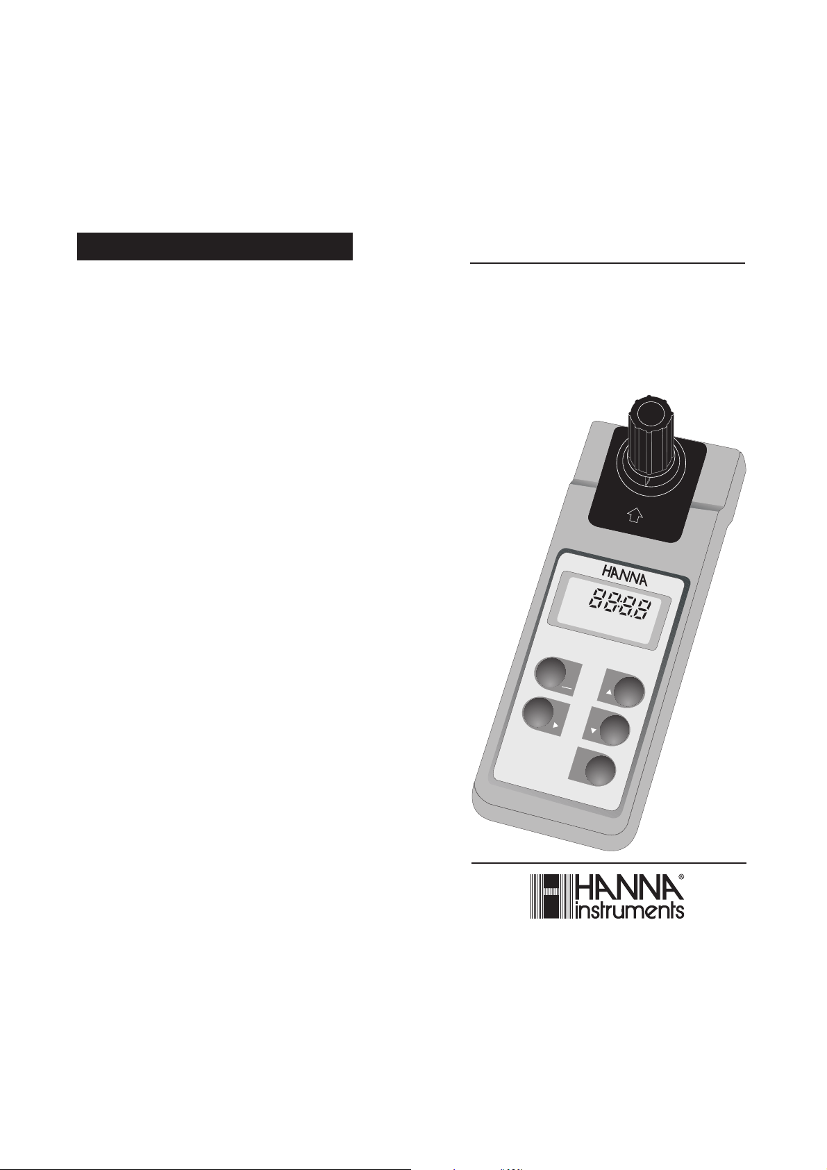
Turbidity Meter with RS232
MAN93703-11R1 08/05
HI 93703-11
Portable Logging
HI9370 3-11HI
GLP
LOGGIN G
LOGGIN G
MICROP ROCESSOR
MICROP ROCESSOR
TURBID ITYMETER
TURBID ITY
METER
LOG
93703- 11
ON
OFF
CAL
CLR
READ
ALT
DATE
188
VIEW
STO
DATE
TIME
LOBAT
%
United Kingdom:
Tel. (01525) 850.855 • Fax (01525) 853.668
USA:
Tel. (401) 765.7500 • Fax (401) 765.7575
For e-mail contacts and complete list of Sales and
Technical offices, please see www.hannainst.com
www.hannainst.com
Page 2

Dear Customer,
Thank you for choosing a Hanna product.
Please read this instruction manual carefully
before using the instrument.
This manual will provide you with the necessary
information for the correct use of the instrument.
If you need additional technical information, do
not hesitate to e-mail us at
tech@hannainst.com
This instrument is in compliance with the
directives.
TABLE OF CONTENTS
Preliminary Examination ............................ 3
General Description.................................... 3
Principle of Operation ................................. 5
Functional Description................................ 6
Specifications ............................................ 7
Operational Guide ...................................... 8
Measurement Procedure ....................... 8
Log-on-demand ................................... 11
Cleaning Logged Data ......................... 11
Viewing Logged Data .......................... 12
Viewing and setting Date and Time ..... 12
Error Codes......................................... 13
Ensure Accurate Measurements ............. 1 4
Sources of Interference....................... 15
Cali brat ion................................................ 16
Calibration Procedure .......................... 16
Viewing Calibration Date ..................... 18
Ensure Accurate Calibration................ 18
Standard Suspension .......................... 19
Battery Replacement ............................... 20
PC Connection......................................... 21
Accessories............................................. 22
Warranty .................................................. 23
2
WARRANTY
All Hanna Instruments meters are warranted
for two years against defects in workmanship
and materials when used for their intended
purpose and maintained according to instructions. This warranty is limited to repair or
replacement free of charge. Damages due to
accidents, misuse, tampering or lack of prescribed maintenance are not covered.
If service is required, contact the dealer from
whom you purchased the instrument. If under
warranty, report the model number, date of
purchase, serial number and the nature of the
failure. First obtain a Returned Goods Authorization number from the Customer Service department, then return the instrument with the
Authorization # included along with shipment
costs prepaid. If the repair is not covered by the
warranty, you will be notified of the charges.
When shipping any instrument, make sure it is
properly packaged for complete protection.
All rights are reserved. Reproduction in whole
or in part is prohibited without the written
consent of the copyright owner.
Recommendations for Users
Before using this product, make sure that it is entirely suitable for the environment
in which it is used.
Operation of this instrument in residential area could cause unacceptable
interferences to radio and TV equipments, requiring the operator to take all
necessary steps to correct interferences.
Any variation introduced by the user to the supplied equipment may degrade
the instrument's EMC performance.
To avoid electrical shock, do not use this instrument when voltages at the
measurement surface exceed 24 Vac or 60 Vdc.
To avoid damages or burns, do not perform any measurement in microwave
ovens.
23
Page 3

ACCESSORIES
PRELIMINARY EXAMINATION
HI 731318 Tissue for wiping cuvets (4 pcs)
HI 731321 Spare glass cuvet (4 pcs)
HI 731313 Maintenance kit: rugged
carrying case including HI
93703-0 and HI 93703-10
calibration solutions, HI 9370350 cuvet cleaning solution, 1
tissue for wiping cuvets and 2
cuvets
HI 93703-0 AMCO-AEPA-1 @0 FTU*
calibration solution, 30 mL
HI 93703-05 AMCO-AEPA-1 @500 FTU*
calibration solution, 30 mL
HI 93703-10 AMCO-AEPA-1 @10 FTU*
calibration solution, 30 mL
HI 93703-50 Cuvet cleaning solution, 230
mL
HI 92000 Windows® compatible software
HI 920011 Serial cable for PC connection
(5 to 9-pin)
* 1 FTU = 1 NTU
22
Remove the instrument from the packing material
and examine it to make sure that no damage has
occurred during shipping. If there is any damage,
notify your Dealer.
HI 93703-11 is supplied complete with:
• Glass cuvet with cap
• Batteries (4 x 1.5V AA)
• Instruction manual
Note: Save all packing material until you are sure
that the instrument functions correctly. Any
defective item must be returned in its original
packaging with the supplied accessories.
GENERAL DESCRIPTION
With HI93703-11 turbidity measurements can
be performed with high precision in the field as
well as in the laboratory. HI93703-11 turbidity
meter is a microprocessor-based instrument
used to determine the turbidity of water and
waste-water. The meter covers a 0-1000 FTU
range in two scales: 0.00 to 50.00 FTU and 50
to 1000 FTU. The autoranging feature of the
instrument sets the appropriate range for the
measurement.
HI 93703-11 also includes a real-time clock and
log-on-demand capability. The PC
communication is made through a serial port of
your computer and the 5-pin socket on the
meter.
Note: HI 93703-11 has been designed
according to the ISO 7027 International
Standard, consequently the turbidity
measurement units are expressed in
FTU (Formazine Turbidity Unit). FTU is
identical to the other internationally
recognized unit: NTU (Nephelometric
Turbidity Unit).
3
Page 4
The meter is housed in a rugged and lightweight
case, with an easy-to-read LCD.
To save battery-life, the instrument is equipped
with an automatic shut-off feature which is
activated after 5-minutes of non-use. This feature is disabled when the meter is connected to
the serial port of the computer.
All operations can be carried out with only five
keys and troubleshooting functions can be
performed with displayed error code guides.
A positive-locking system guarantees that the
cuvet is firmly placed in the cell.
The keypad is water-resistant and can be wiped
with a moist cloth for quick cleanups.
Two or three point calibration (0,10, 500 FTU*)
can be easily performed using available standards, and the last calibration date is automatically stored for future retrivial.
We have chosen 10 FTU * as the standard
calibration point because it best fits the
water turbidity measurements in different
applications, from drinking water to wastewater treatment.
HANNA instruments® uses the primary standard AMCO-AEPA-1 to avoid all formazinerelated problems. Formazine is a toxic, unstable substance, which requires particular care:
its standards have to be prepared only a few
minutes before performing the calibration, and
cannot be reused because of their short life.
HANNA instruments® standards are extremely
stable, can be reused, and last up to six
months, if free from contamination.
HI 93703-11 can be used with both standards.
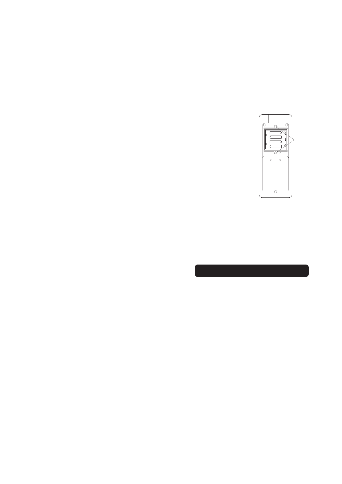
Battery replacement must only take place in a
safe area and using 1.5V AA alkaline batteries.
To install or replace the
batteries, turn the unit off
and remove the battery
compartment cover on the
raer of the meter.
-
1.5V
+
-
1.5V
+
-
1.5V
1.5V
+
SCREW
+
POTS
-
Insert the new batteries
while paying attention to
the polarity.
After the batteries have been installed, close the
battery cover and make sure the gasket is in
place before tightening the 2 screws, to ensure
a watertight seal.
PC CONNECTION
To communicate with the instrument through
the HI 92000 software, use the HI 920011 cable
(optional) to connect a serial port of your computer to the 5 pin connector of the meter.
When connected the meter will maintain full
functionality, being able to perform a data transfer while the meter is being operated.
Notes:
• Serial communication is not allowed when the
meter is being calibrated.
• The auto shut-off feature is also disabled when
the meter is connected to a computer.
* 1 FTU = 1 NTU
4
21
Page 5

BATTERY REPLACEMENT
PRINCIPLE OF OPERATION
All components have been selected to minimize current drain without compromising functionality. In order to minimize the battery consumption, the meter is equipped with an autoshut off function which switches the meter off
after 5 minutes of non-use.
The four 1.5V batteries guarantee 60 hours of
working life (or 900 measurements).
In order to obtain accurate measurements, the
battery level is monitored every time the meter
is switched on.
LOBAT
In addition, a "LO BAT" indication will appear on
the lower right corner of the display when the
batteries are weak (<10%). All four batteries
need to be replaced.
0
%
LO BAT
When the batteries are too weak to ensure
reliable measurements, the message 0% LO
BAT appears for a few seconds, and then the
meter will automatically switch itself off. Replace the batteries immediately.
HI 93703-11 has been designed to perform
measurements according to the ISO 7027 International Standard.
The instrument functions by passing a beam of
infrared light through a vial containing the sample
being measured.
LIGHT
DETECTOR
IR LED
EMITTED LIGHT (890 nm)
90° SCATTERED
CUVET
LIGHT
A sensor, positioned at 90° with respect to the
direction of light, detects the amount of light
scattered by the undissolved particles present
in the sample. The microprocessor converts
such readings into FTU* values.
As noted above, FTU unit is equal to the NTU
unit. However, there are other known measurement units for turbidity: Jackson Turbidity Unit
(JTU) based on the old method of Jackson's
candle, and Silica Unit (mg/L of SiO2). For your
reference the conversion table between these
measurement units is shown below:
JTU FTU/NTU SiO2 (mg/L)
JTU 1 19 2.5
FTU/NTU 0.053 1 0.13
SiO2 (mg/L) 0.4 7.5 1
20
* 1 FTU = 1 NTU
5
Page 6

FUNCTIONAL DESCRIPTION
8
1
2
LOG LOBAT
HI 93703-11
35
4
CLRCLR
ON
OFF
CALCAL
GLPGLP
LOGGING
LOGGING
MICROPR OCESSOR
MICROPR OCESSOR
TURBIDI TYMETER
TURBIDI TY
METER
188
VIE WVIE W
STOSTO
DATEDATE
REA DREA D
ALTALT
DATE
TIME
%
6
7
1) Measurement cell
2 ) LCD (Liquid Crystal Display)
3) ON/OFF/CLR key, to turn the meter ON
and OFF, and to clear log memory
4) GLP/CAL key, to display last calibration
date & time, and to enter calibration mode
5) STO/VIEW key, to store sample after reading, and to view log memory
6) READ/DATE key, to perform measurements, and to display (toggle) current
date/time
7 ) ALT key, to activate the second functions
(second function keys in orange)
8 ) RS232 connector (5 pin)
6
• All glassware that comes into contact with
standards should be maintained clean. Wash
with the HI93703-50 cleaning solution and
rinse with HI 93703-0 or turbidity free water.
• Rinse the vial twice with 5 ml of the liquid to
be tested. This removes the effect of any
previous liquid and any dust or foreign objects that may be present inside. Gently pour
the liquid down the side of the vial to reduce
air bubbles (no mixing is required when HI
93703-0 and HI 93703-10 AMCO-AEPA-1
standards are used).
• Before inserting the vial into the instrument,
wipe it with HI93703-70 or a soft, lint-free
tissue. Handle vials so that no fingerprints
can get on the areas where light passes
(approx. bottom 2 cm/1").
STANDARD SUSPENSION
Presently, there are only two recognized primary standards: AMCO-AEPA-1 and formazine.
Hanna supplies HI 93703-11 with the AMCO-
AEPA-1 which has a much longer shelf life at all
concentrations (approx. six months, if free from
contamination). In addition, no special handling
or disposal is required and a much higher
stability of suspended particles has been observed.
On the other hand, formazine is a toxic substance, generated by a known carcinogen, with
poor stability (particles flocculate and settle
quickly). Lower concentrations change value
within a few days or hours after dilution.
The consistency of HI 93703-11 readings by
using both standards has been separately established by Advanced Polymer Systems and
Hanna Instruments.
Additional documentation about the formazine
standard and more complex calibration procedures is available upon request.
* 1 FTU = 1 NTU
19
Page 7

• After approximately
30 seconds the LCD
will display "----".
Now the instrument
is calibrated and
ready for use.
NOTE: If "ERR1" is displayed, the calibra-
tion data is maintained.
VIEWING CALIBRATION DATE
To display the last calibration time and date,
press the GLP button to
toggle through the date
and time. If the display
shows "FS", the instru-
HI 93703-11
CLRCLR
ON
OFF
CALCAL
GLPGLP
LOGGING
LOGGING
MICROPRO CESSOR
MICROPRO CESSOR
TURBIDIT Y
TURBIDIT YMETER
METER
VIE WVIEW
STOSTO
DATEDATE
REA DREA D
ALTALT
ment has factory calibration settings loaded and
no date will be displayed.
FS
VIEWING FIRMWARE VERSION
To display the firmware version press and
hold the ON/OFF key for
approx. ten seconds
(when turning the meter
on).
HI 93703-11
CLRCLR
ON
OFF
CALCAL
GLPGLP
LOGGING
LOGGING
MICROPROC ESSOR
MICROPROC ESSOR
METER
TURBIDITY
TURBIDITYMETER
VIE WVIEW
STOSTO
DATEDATE
REA DREAD
ALTALT
The firmware version will
be displayed
V1.0
SPECIFICATIONS
Range 0.00 to 50.00 FTU *
50 to 1000 FTU *
Resolution 0.01 and 1 FTU *
Accuracy ±0.5 FTU* or
±5% of reading (whichever is greater)
Typical EMC Deviation ±2% FS
Calibration 3 point (0, 10 and 500 FTU*)
Light Source Infrared LED
Light Source Life Life of the instrument
Light Detector Silicon photocell
Data Logging 199 measurements, on-demand
PC Connection Through serial port,
using HI 920011 connection cable and
HI 92000 Windows® compatible software
Battery Type 4 x 1.5V AA alkaline batteries
Battery Life Approx. 60 hours of continuous use
or 900 measurements
Auto-off After 5 minutes of non-use
Environment 0 to 50
RH max 95% non-condensing
Dimensions 220 x 82 x 66 mm
Weight 510 g (1.1 lb.)
°
C (32 to 122°F);
(8.7 x 3.2 x 2.6")
ENSURE ACCURATE CALIBRATION
The procedure below should be carefully followed during testing and calibration:
18
* 1 FTU = 1 NTU
7
Page 8

OPERATIONAL GUIDE
To prepare the instrument for taking
measurements, first install the batteries (see
Battery Replacement section on page 20) and
then turn the instrument on.
To maximize battery-life, the display is
automatically switched off after 5-minutes of
non-use. To reactivate the display, simply
press the ON/OFF key.
MEASUREMENT PROCEDURE:
HI 93703-11
CLRCLR
VIEWVIE W
• Turn the meter on by
pressing the ON/OFF
key.
ON
OFF
CALCAL
GLPGLP
LOGGING
LOGGING
MICROPROC ESSOR
MICROPROC ESSOR
METER
TURBIDITY
TURBIDITYMETER
STOSTO
DATEDATE
READREAD
ALTALT
• The meter will carry
out a self-test displaying a full set of figures.
LOG LOBAT
188
DATE %
TIME
• The meter will carry
out a battery test showing in percentage the
98
ba
%
battery life left.
• If "ERR1" appearson
the LCD, please check
the standard solution.
err1
• After approximately 30 seconds the meter
will display 10.00, prompting the user to
place the 10.00 FTU standard solution in
the cuvet holder.
10.00
cl
• Place the 10.00 FTU
standard in the holder press CAL, SIP and
CL will start blinking
sip
• After approximately
30 seconds the meter
will display 500, asking the user to place
the 500 FTU buffer
solution in the cuvet
holder.
NOTE: At this point the
user can save the two point calibration
setup by pressing ALT & CAL buttons,
leaving the calibration mode.
cl
500
cl
• When the LCD displays “--- -” the meter
is ready to measure.
• Fill a clean cuvet up to one quarter inch (0.5 cm) from its rim with
the thoroughly agitated sample.
• Allow sufficient time for bubbles
to escape before securing the cap.
Note: do not overtighten the cap.
8
1/4“
To perform a three point
calibration, place the 500
FTU standard solution in the
cuvet holder.
• Press CAL, SIP and
0.5 cm
CL will start blinking
17
sip
cl
Page 9

CALIBRATION
To check the date of last calibration, simply
press the GLP/CAL key. Press again to
toggle between date and time.
To make sure that the meter is calibrated, take
a measure of a standard solution.
The instrument can be calibrated at two or three
points and a monthly calibration is recommended.
CALIBRATION PROCEDURE
• Turn the meter on and
wait for the display to
show "----".
NOTE: Wipe the cuvet thoroughly with a lint-
free tissue (HI 93703-70 ) before inserting into the measurement cell.
The cuvet must be completely free of
fingerprints and other oil or dirt, particularly in the area where the light
goes through (approx. the bottom
2 cm/1").
• Place the cuvet into
the cell and check
that the notch on the
cap is positioned securely into the
groove.
• Press the ALT & CAL
buttons together. The
"CAL" message will
blink on the display 3
times. The meter then
enters the calibration
mode, displaying "0.00
cl" and prompting the
user to insert the 0.00
FTU standard.
• Place the 0.00 FTU standard in the cuvet holder
• Press CAL, SIP and
CL will start blinking
HI 93703-11
CLRCLR
VIEWV IEW
ON
STOSTO
OFF
CALCAL
DATEDATE
GLPGLP
READRE AD
LOGGING
LOGGING
ALTALT
MICROPROCE SSOR
MICROPROCE SSOR
TURBIDITY
TURBIDITYMETER
METER
0.00
cl
sip
cl
• The mark on the
cuvet cap should
point towards the
LCD.
• Press the READ key
and the LCD will display a blinking “SIP”
(Sampling in Process). The turbidity
value will appear after approx. 20 seconds.
HI 93703-11
CLRCL R
ON
OFF
CALCA L
GLPGL P
LOGGING
LOGGING
MICROPROC ESSOR
MICROPROC ESSOR
METER
TURBIDITY
TURBIDITYMETER
VIE WVI EW
STOST O
DATEDAT E
REA DR EAD
ALTALT
51
16
9
Page 10

• Even though HI93703-11 covers a very
wide range of turbidity values, for very
accurate measurements of samples exceeding 40FTU *, Standard Methods require dilution. In such cases, the correct
amount of HI93703-0 or turbidity-free
water to be added to the sample can be
calculated as follows:
Vos = 3000 / T
where: Vos = volume of sample (mL) to be
combined with HI 93703-0 to
obtain the final volume of 100mL.
T = HI 93703 reading (exceeding
40FTU*)
E.g.:HI 93703 reading = 200 FTU *
3000 / 200 = 15 mL (Vos)
15 mL (Vos)+85 mL (HI93703-0) = 100 mL
At this point, take a sample of this solution
and measure its turbidity.
The correct turbidity value of the original
sample will be:
Tn x 100 mL / Vos = T
a
where: Tn = new HI 93703 reading
Ta = actual turbidity value of the original
sample
E.g. If Tn = 27 FTU *
Ta = 27 FTU *x100 mL / 15 mL = 180 FTU *
NOTE: Any sample taken above 1000 FTU will
show out of range by blinking "1000".
hours (the sample needs to be kept at room
temperature prior to the analysis).
• To obtain a representative sample, gently,
but thoroughly, mix it before samples are
taken. Do not shake (to prevent air bubbles)
and do not let the sample settle.
• It is recommended to calibrate the meter with
the supplied HI93703-10 @10 FTU* standard at least once a month or more frequently
for greater accuracy.
• Before inserting vials into the instrument,
wipe them with HI93703 -70 or a soft, lintfree tissue. Handle vials so that no fingerprints get on the areas where light passes
(approx. the bottom 2 cm/1 inch).
If you experience any problems in taking measurements, contact your dealer or the nearest
Hanna Customer Service Center.
SOURCES OF INTERFERENCE
• Presence of floating debris and coarse sedi-
ments which settle out rapidly will give false
readings.
• The infrared light source used for HI 9370311 turbidity meter, complies with the ISO
7027 International Standard and can effectively minimize any errors due to colored
dissolved substances. This effect, called
"true color", is a common interference for
most commercially available instruments
operating in the range of visible light.
• Air bubbles and the effect of vibrations that
disturb the surface of the sample may give
false results and should be avoided.
• Dirty glassware could also affect readings
along with scratched or dented vials.
* 1 FTU = 1 NTU
10
* 1 FTU = 1 NTU
15
Page 11

• Real Time Clock
error ∗
• EEPROM error∗
• Internal communica-
err2
err3
err4
tion error∗
• Internal Bus error∗
Contact the HANNA office nearest to you.
∗
err5
LOG-ON-DEMAND:
• After taking a read-
ing, press the STO
button. The last
sample read will be
stored in memory.
The display will also
show on the bottom
HI 93703-11
CLRCLR
ON
OFF
CALCAL
GLPGLP
LOGGING
LOGGING
MICROPRO CESSOR
MICROPRO CESSOR
TURBIDIT Y
TURBIDIT YMETE R
METER
VIE WVIEW
STOSTO
DATEDATE
REA DREA D
ALTALT
right corner the reference number of the
stored sample.
NOTE: When the maximum number of samples
has been reached
(199), the LCD display will show "FULL".
FULL
This is a warning that
you will be overwriting the oldest sample recorded. To store the
current sample, press the STO button again
and this will overwrite the oldest sample in the
memory. All samples are shifted (reference
numbers reduced by one). Sample number
one remains the oldest sample.
ENSURE ACCURATE MEASUREMENTS
• Each time the cuvet is used, tighten the cap
to the same degree.
• Discard the sample soon after the reading is
taken to avoid permanently clouding the glass.
• All glassware used to contain the standards
and the samples should be maintained clean,
washed with the HI93703-50 cleaning solution
and rinsed with HI 93703-0 or turbidity-free
water.
• Collect the samples in clean glass or plastic
bottles, fit stoppers and perform the analysis
quickly. If necessary, store the sample in a
cool, dark place, for up to a maximum of 24
14
CLEARING LOGGED DATA:
HI 93703-11
• Press the ALT &
CLR buttons together. The display
will show "CLR" for
confirmation. Press
CLRC LR
ON
OFF
CALC AL
GLPG LP
LOGGING
LOGGING
MICROPROC ESSOR
MICROPROC ESSOR
METER
TURBIDITYMETER
TURBIDITY
VIE WVI EW
STOS TO
DATEDAT E
REA DREAD
ALTALT
ALT & CLR again to
clear memory. To
abort the operation,
press any button.
CLR
LOG
ALL SAMPLES PREVIOUSLY STORED
WILL BE ERASED FROM MEMORY!
11
Page 12

VIEWING LOGGED DATA:
• Press the ALT & VIEW
buttons together. The
last sample will be displayed.
• Press the right arrow to
scroll between turbidity
value, date and time of
the sample.
• Press the UP/DOWN
arrows to view the
samples and use the
right arrow to scroll the
date and time .
HI 93703-11
CLRCLR
ON
OFF
CALCAL
GLPGLP
LOGGING
LOGGING
MICROPROC ESSOR
MICROPROC ESSOR
METER
TURBIDITYMETER
TURBIDITY
HI 93703-11
LOGGING
LOGGING
MICROPROC ESSOR
MICROPROC ESSOR
TURBIDITYMETER
TURBIDITY
VIEWVIE W
STOSTO
DATEDATE
READREAD
ALTALT
HI 93703-11
LOGGING
LOGGING
MICROPROC ESSOR
MICROPROC ESSOR
TURBIDITY
TURBIDITYMETER
CLRC LR
VIE WVI EW
ON
STOS TO
OFF
CALC AL
DATEDAT E
GLPG LP
REA DR EAD
ALTALT
METER
CLRC LR
ON
OFF
CALC AL
GLPG LP
METER
VIE WV IEW
STOS TO
DATEDATE
REA DREAD
ALTA LT
• Press ALT & VIEW again to exit this mode.
month and day, use UP/
DOWN to set.
• Press right arrow again
to scroll to time, use UP/
DOWN to set.
• Press right arrow again
to save and exit date
and time setup.
LOGGING
LOGGING
MICROPROC ESSOR
MICROPROC ESSOR
TURBIDITYMETER
TURBIDITY
HI 93703-11
CLRCLR
ON
OFF
CALCAL
GLPGLP
LOGGING
LOGGING
MICROPROCE SSOR
MICROPROCE SSOR
METER
TURBIDITY
TURBIDITYMETER
HI 93703-11
VIEWVI EW
STOSTO
DATEDAT E
READREA D
ALTALT
CLRC LR
ON
OFF
CALC AL
GLPG LP
METER
VIE WVI EW
STOS TO
DATED ATE
REA DREAD
ALTA LT
Note: Press ALT & DATE to leave this mode
without saving.
ERROR CODES:
Every time the meter is switched on, the Real
Time Clock and EEPROM are tested, and if an
error is found the corresponding error code will
be displayed.
VIEWING AND SETTING DATE AND TIME:
VIEWING:
• Press ALT & DATE to toggle
between date and time.
SETTING:
• Press and hold ALT & DATE
for 3-4 seconds.
• Press UP/DOWN to correct
and set the year.
• Press right arrow to scroll to
12
HI 93703-11
CLRCLR
OFF
CALCAL
GLPGLP
LOGGING
LOGGING
MICROPROCES SOR
MICROPROCES SOR
METER
TURBIDITY
TURBIDITYMETER
HI 93703-11
LOGGING
LOGGING
MICROPROCESS OR
MICROPROCESS OR
METER
TURBIDITYMETER
TURBIDITY
VIEWVIEW
ON
STOSTO
DATEDATE
READREAD
ALTALT
CLRCLR
VIEWVIEW
ON
OFF
STOSTO
CALCAL
DATEDATE
GLPGLP
READREA D
ALTALT
The list of error codes is as follows:
• NO cover error
cap
(check cuvet position)
• Calibration error
err1
(check calibration
standard value)
13
 Loading...