

Page 1
Instruction Manual
HI 93414
Turbidity and Free/Total Chlorine
Meter
www.hannainst.com
1
Page 2

Dear Customer,
Thank you for choosing a Hanna Instruments product. This manual will provide you with the
necessary information for correct use of the instrument.
Please read this instruction manual carefully before using the instrument.
If you need additional technical information, do not hesitate to e-mail us at tech@hannainst.com
or see the back side of this manual for our worldwide sales and technical service contacts.
This instrument is in compliance with
directives.
WARRANTY
HI 93414 is warranted for two years against defects in workmanship and materials when used for
its intended purpose and maintained according to instructions. This warranty is limited to repair or
replacement free of charge.
Damage due to accidents, misuse, tampering or lack of prescribed maintenance is not covered.
If service is required, contact the dealer from whom you purchased the instrument. If under
warranty, report the model number, date of purchase, serial number and the nature of the failure.
If the repair is not covered by the warranty, you will be notified of the charges incurred. If the
instrument is to be returned to Hanna Instruments, first obtain a Returned Goods Authorization
number from the Technical Service Department and then send it with shipping costs prepaid. When
shipping any instrument, make sure it is properly packed for complete protection.
To validate your warranty, fill out and return the enclosed warranty card within 14 days from the
date of purchase.
TABLE OF CONTENTS
WARRANTY ............................................................................................................................................. 2
PRELIMINARY EXAMINATION ................................................................................................................... 3
GENERAL DESCRIPTION ........................................................................................................................... 4
TAG IDENTIFICATION SYSTEM .................................................................................................................. 5
ABBREVIATIONS ..................................................................................................................................... 5
PRINCIPLE OF OPERATION ...................................................................................................................... 6
FUNCTIONAL DESCRIPTION ..................................................................................................................... 9
SPECIFICATIONS ................................................................................................................................... 12
GENERAL TIPS FOR AN ACCURATE MEASUREMENT .................................................................................. 14
RANGE SELECTION ................................................................................................................................ 21
MEASUREMENT PROCEDURE .................................................................................................................. 22
CALIBRATION PROCEDURE..................................................................................................................... 28
LOGGING.............................................................................................................................................. 37
GOOD LABORATORY PRACTICE (GLP) ...................................................................................................... 40
SETUP ................................................................................................................................................. 42
LCD BACKLIGHT .................................................................................................................................... 46
TAG INSTALLATION............................................................................................................................... 47
LAMP REPLACEMENT ............................................................................................................................. 47
BATTERIES MANAGEMENT ..................................................................................................................... 48
PC INTERFACE ....................................................................................................................................... 50
ERROR CODES ...................................................................................................................................... 50
ACCESSORIES ....................................................................................................................................... 51
RECOMMENDATIONS FOR USERS .......................................................................................................... 51
2
Page 3
PRELIMINARY EXAMINATION
Please examine this Product carefully. Make sure the instrument is not damaged. If any damage has
occurred during the shipment, please notify your dealer.
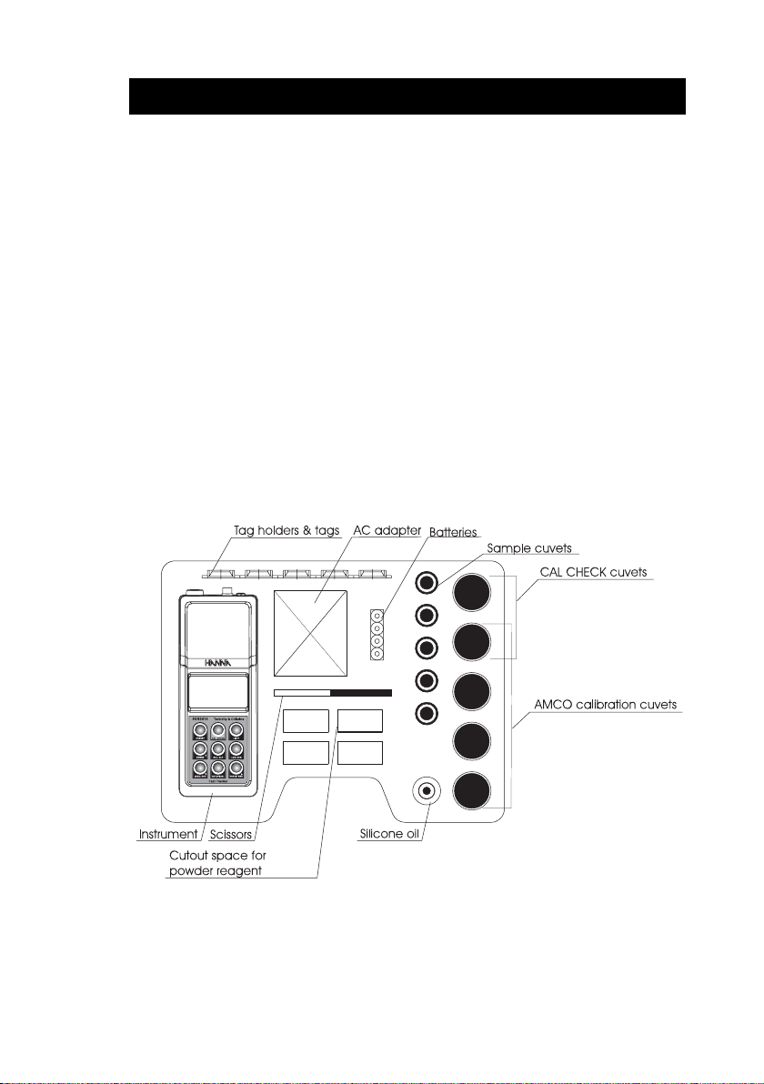
This HI 93414 Portable Turbidity and Free/Total Chlorine meter is supplied complete with:
• Five Sample Cuvets and Caps
• Calibration Cuvets for turbidimeter
• Calibration Cuvets for colorimeter
• Silicone Oil
• Tissue for wiping the cuvets
• Five Tag holders with Tags (HI 920005)
• Scissors
• Batteries (4 pcs.)
• AC Adapter
• Instruction Manual
• Instrument Quality Certificate
• Rigid carrying case
Note:Save all packing material until you are sure that the instrument works correctly. Any
defective item must be returned in the original packing with the supplied accessories.
3
Page 4

GENERAL DESCRIPTION
GENERAL DESCRIPTION
HI 93414 is a high accuracy, combined meter that benefits from Hanna’s years of experience as
manufacturer of analytical instruments.
The HI 93414 successfully combines turbidity and colorimetric measurements to meet the needs of
measuring the most important parameters of drinking water: turbidity and free/total chlorine. The
meter is especially designed for water quality measurements, providing reliable and accurate
readings on low turbidity and chlorine values. The HI 93414 meets and exceeds the requirements of
USEPA and Standard Methods both for turbidity and colorimetric measurements.
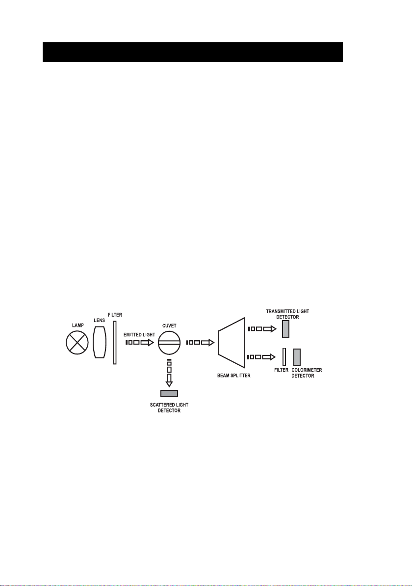
The instrument is based on a state-of-the-art optical system which guarantees accurate results. The
optical system, consisting in a tungsten filament lamp, three detectors (scattered,transmitted for
turbidimeter range and one for colorimeter range), and a narrow band interference filter @ 525 nm
assures long term stability and minimizes stray light and color interferences. It also compensates for
variations in intensity of the lamp, making no need for frequent calibration.
The 25 mm round cuvets made from special optical glass guarantee the repeatability and consistency
of the measurements.
Turbidity measurements can be made in the 0.00 to 1000 NTU (Nephelometric Turbidity Units)
range. The instrument has an EPA compliance reading mode which rounds the reading to meet EPA
reporting requirements.
Depending on the measured sample and needed accuracy, normal measurement, continuous
measurement or signal averaging measurement can be selected.
Free or Total Chlorine measurements can be made in the 0.00 to 5.00 mg/L (ppm) range.
With the powerful CAL CHECK™ function, the good performance of the instrument can be validated
at any moment by using the exclusive Hanna ready-made, NIST traceable standards.
Calibration can be performed at any time for turbidity and for colorimetric range.
For turbidity, a two, three or four-point calibration is available using the supplied (<0.1, 15, 100
and 750 NTU adjustable calibration points) or user prepared standards. For colorimeter, a one-point
calibration can be performed.
HI 93414 has complete G.L.P. (Good Laboratory Practice) functions that allows traceability of the
calibration conditions. The last calibration points, time and date can be checked by a single key
touch. HI 93414 has a user-friendly interface with an easy to read, large Liquid Cristal Display.
Displayed codes guide the user step by step with routine operation and through calibration. Confirmation
and error acoustic signals help the user during instrument operation.
The HI 93414 combined meter is a truly portable instrument. It is supplied with a rigid carrying
suitcase that offer protection for harsh environments. The instrument is also splash proof.
One battery set is enough for at least 1500 measurements. The battery charging percentage and low
battery condition is displayed on the LCD to avoid unexpected battery failure. In addition, the
instrument has an auto shut-off feature and turns off after 15 minutes of non-use to save batteries life.
The instrument is equipped with backlight and the current time is displayed continuously on the LCD.
4
Page 5

The instrument also provides a logging function. Up to 200 measurements can be stored in the
internal memory and consulted at any time. In order to further store and analyse, the data can be
downloaded to a PC using one of the available ports: RS232 or USB.
For advanced field applications, the HI 93414 combined meter is equipped with Tag Identification
System (TIS) that make data collecting and management simpler than ever.
TAG IDENTIFICATION SYSTEM
Hanna is the first manufacturer of analytical instruments that has decided to add the unique T.I.S.Tag Identification System to its meters, to meet the more restrictive needs of the users and fit all
advantages of this system to the turbidity and chlorine measurements to simplify data management.
The system is designed for scientific and industrial applications, or to prove during safety audits and
inspections that samples have been truly taken on pre-established locations.
The system is as easy to install as to operate. Just fix the so-called
sites that need to be checked often, and with this the T.I.S. is setup. The tag contains a computer chip
embedded in a durable stainless steel can. It is designed to withstand the harsh environments,
indoors or outdoors. The number of tags that can be installed is practically unlimited, because each
tag has a unique identification code.
Immediately after tags installation, data collecting can be started. Use the HI 93414 to take
measurements and memorize the test result by pressing the Log-on-Demand key. Then, the instrument
will ask for the tag identification.
Simply touching the
authenticate logging, by storing the
iButton® with the matching connector on the HI 93414 does identify and
iButton® serial number, time and date stamp.
The power of the T.I.S. feature resides in the PC application. Download all test data to your PC and
®
use our HI 92000 Windows
compatible application software for further data management. You can
sort or filter all your collected test data on different criteria like on a specific sampling location,
parameter, date and time intervals, or fix range to filter measured values. The data can be plotted in
®
a graph, exported to other common Windows
applications or printed for reporting purposes.
It is possible to add also new tags later on, thus increasing an already existing database. Each time the
PC software recognizes a new added tag, it will ask for a description of the new sampling location.
iButton® tags near your sampling
ABBREVIATIONS
NTU Nephelometric Turbidity Units
JTU Jackson Turbidity Units
FTU Formazin Turbidity Units
USEPA US Environmental Protection Agency
LCD Liquid Crystal Display
iButton® is registered Trademark of “MAXIM/DALLAS semiconductor Corp.”
RTC Real Time Clock
RH Relative Humidity
TIS Tag Identification System
ID Identification
5
Page 6
PRINCIPLE OF OPERATION
TURBIDIMETER
Turbidity of water is an optical property that causes light to be scattered and absorbed, rather than
transmitted. The scattering of the light that passes through a liquid is primarily caused by the suspended
solids. The higher the turbidity, the greater the amount of scattered light. Because even the molecules
in a very pure fluid scatter light to a certain degree, no solution will have zero turbidity.
The USEPA Method 180.1 specify the key parameters for the optical system to measure turbidity
for drinking, saline and surface water in a 0 to 40 NTU range, using the nephelometric method.
The HI 93414 instrument is designed to meet or exceed the criteria specified by the USEPA Method
180.1 and Standard Method 2130 B.
The light beam that passes through the sample is scattered in all directions. The intensity and pattern
of the scattered light is affected by many variables like wavelenght of the incident light, particle size,
shape, refractive index and color.
The Hanna’s HI 93414 is based on a state-of-the-art optical system that guarantee both high
performance and reliable results.
This optical system includes a tungsten filament lamp, a scattered light detector (90
0
transmitted light detector (180
). For the colorimeter range the optical system is based on the
turbidimeter tungsten lamp and a separate detector with a narrow band interference filter @ 525
nm to guarantee both high performance and reliable results for colorimetric measurements.
0
) and a
For the turbidimeter range the microprocessor of the instrument calculates from the signals that
reaches the two detectors, the NTU value, using an effective algorithm. This algorithm corrects and
compensates for interferences of color, making the HI 93414 instrument color-compensated.
The optical system and measuring technique alow the compensation of lamp intensity fluctuations,
minimizing the need of frequent calibration.
The lower detection limit of a turbidimeter is determined by the so called “stray light”. Stray light is the light
detected by the sensors, that is not caused by light scattering from suspended particles.
The optical system of HI 93414 instrument is designed to have very low stray light, providing accurate
results for low turbidity samples. However, special care must be taken when measuring low turbidities (see
page 14 “General Tips for an Accurate Measurement” for sample preparation and measuring techniques).
6
Page 7

MEASUREMENT UNITS
)
Many methods were used to measure turbidity over the years. The Jackson Candle Turbidimeter was
used to measure turbidity as Jackson turbidity units (JTU). The Secchi Disk is commonly used to
measure turbidity in lakes and other deep waters (mg/L SiO
). Both methods are visual and are not
2
considered very accurate. To obtain more accurate readings a nephelometer should be used as a
turbidity reading instrument.
The HI 93414 turbidimeter reports the measurements only in NTU (Nephelometric Turbidity
Units). NTU units are equal to FTU units (Formazine Turbidity Units). The conversion table
between these measurement units is shown bellow:
COLORIMETER
UTJ UTF/UTN OiS
UTJ 1 91 05.2
UTF/UTN 350.0 1 31.0
OiS
)L/gm( 4.0 5.7 1
2
L/gm(
2
Absorption of light is a typical phenomenon of interaction between electromagnetic radiation and
matter. When light beam crosses a substance, some of the radiation may be absorbed by atoms,
molecules or crystal lattices.
If pure absorption occurs, the fraction of absorbed light depends both on the optical path length
through the matter and on the physical-chemical characteristics of the substance, according to the
Lambert-Beer law:
= ε
–log I/I
o
c d
λ
or
ε
λ
c d
A =
Where:
–log I/I
= Absorbance (A)
o
I
= intensity of incident light beam
o
I = intensity of light beam after absorption
ε
= molar extinction coefficient at wavelength λ
λ
c = molar concentration of the substance
d = optical path through the substance
7
Page 8

Therefore, the concentration “c” can be calculated from the absorbance of the substance as the other
factors are known.
Photometric chemical analysis is based on the possibility to develop an absorbing compound from a
specific chemical reaction between sample and reagents. Given that the absorption of a compound
strictly depends on the wavelength of the incident light beam, a narrow spectral bandwidth should be
selected as well as a proper central wavelength to optimize measurements.
The measurement process is carried out in two phases: first the instrument is zeroed and then the
actual measurement is performed.
8
Page 9
FUNCTIONAL DESCRIPTION
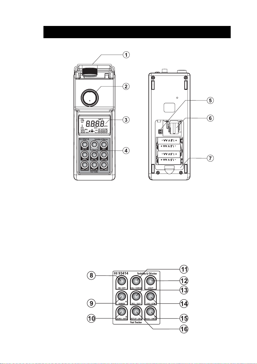
INSTRUMENT DESCRIPTION
1) Cuvet Lid. Close the cuvet lid prior to start a measurement.
2) Cuvet Holder. Insert the cuvet into the holder with the cuvet mark matching the case mark.
3) Liquid Crystal Display (LCD). The LCD has backlight for better visibility in dark environments.
4) Keypad. Splash proof resistant.
5) Lamp connector. Connect the new lamp using a screwdriver during lamp changing procedure.
6) Lamp. Replaceable tungsten lamp.
7) Battery Lid. Remove the battery lid in order to change batteries or replace the lamp.
KEYPAD DESCRIPTION
9
Page 10
8) ON/OFF, press to turn the instrument ON/OFF. If no key is pressed for more than 15
minutes, the instrument automatically shuts off.
9) RANGE
chlorine range. In SETUP it is used to increase the set values. In Log Recall it is used to
select a newer record (scroll up).
10) ZERO/AVG
colorimeter range it is used to make a zero reading. In SETUP it is used to decrease the set
values. In Log Recall it is used to select an older record (scroll down).
11) CAL/CHECK, press and hold for 3 seconds to enter calibration. In colorimeter range it is used
to check the calibration. In SETUP it is used to start/stop editing a parameter.
12) LIGHT, press to turn ON/OFF the backlight.
13) RCL/GLP, press to enter/exit viewing log content or press and hold for 3 seconds to enter the
GLP feature.
14) LOG/CFM, press to save the log records. In SETUP it is used to confirm the selected option.
15) READ/TIMER
measurement in turbidimeter range. In colorimeter range press for 3 seconds to start the
timer for free and total chlorine measurement. In Log Recall it is used to see the content of
a record. In GLP it is used to see all available informations. In SETUP, during date or time
editing, it is used to move the focus on the next setting item.
16) SETUP/DEL, press to enter/exit SETUP. The DEL function is available in Log Recall to delete
calibration or one/all records. In GLP it is used to delete the user calibration.
, press to change the range. You can choose between turbidimeter or free or total
, press to set the average reading mode ON/OFF in turbidimeter range. In
, press to start a measurement. Press and hold to make a continuous
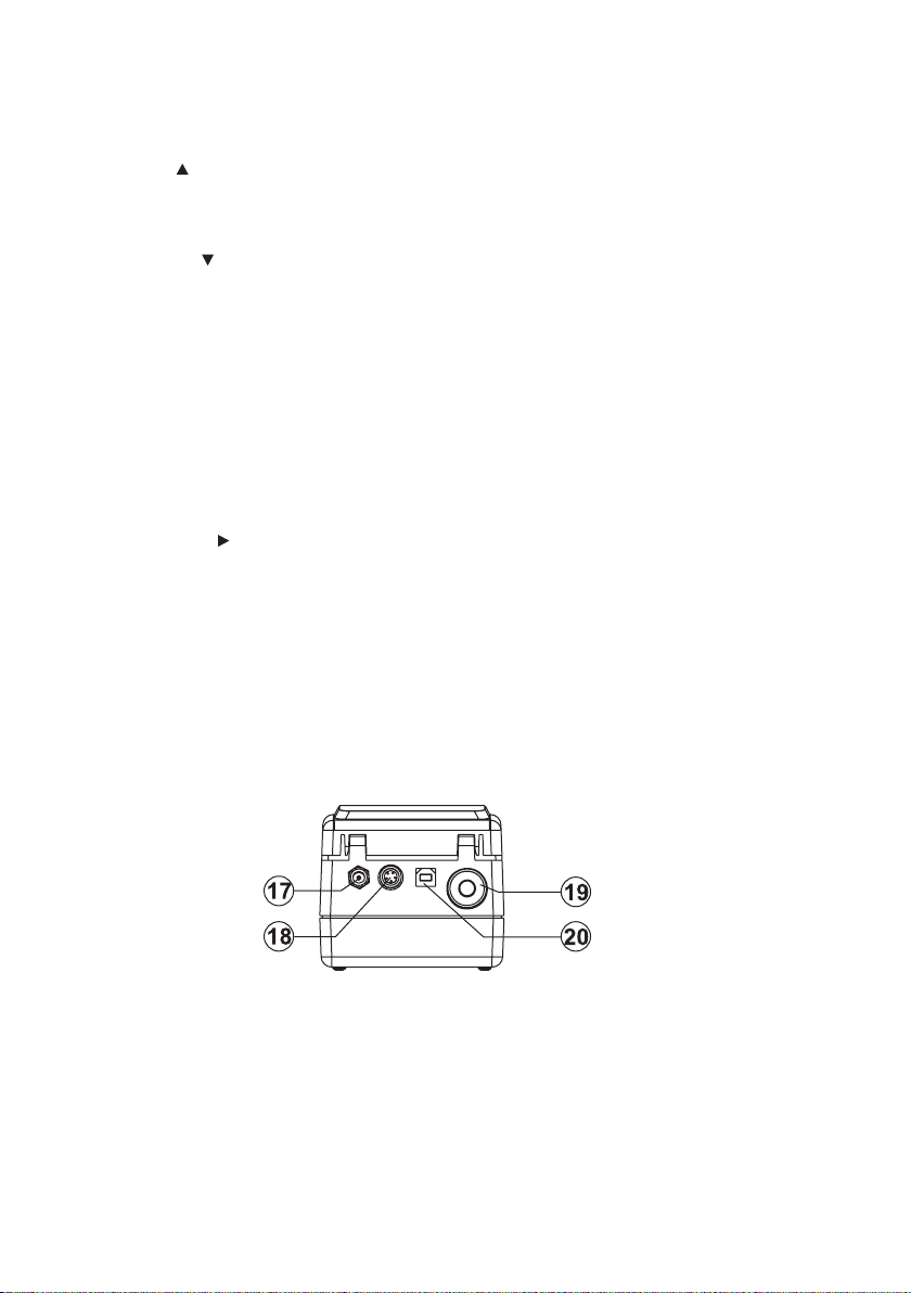
CONNECTORS DESCRIPTION
17) AC adapter connector, used to connect an external AC Adapter.
18) RS232 connector, used to transfer data through the RS232 connection. Use HI 920011
serial cable to connect to the PC.
19) Tag reader connector. Touch the tag with the connector to read the location identification
number during logging.
20) USB connector, used to transfer data to the PC.
10
Page 11
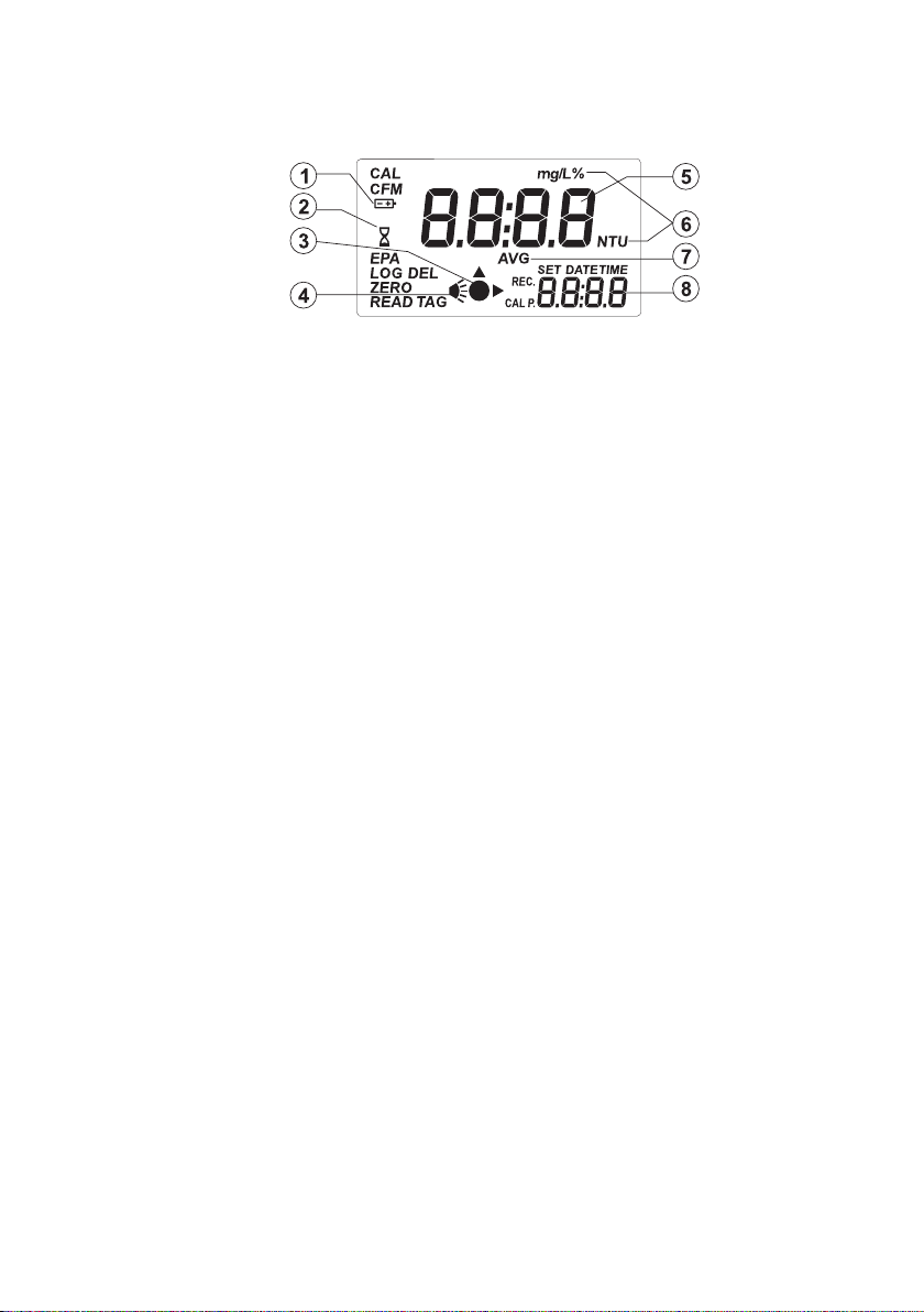
DISPLAY DESCRIPTION
1) Battery icon. When the instrument is powered by batteries, at the start of the instrument, the
remaining battery life is displayed along with the battery icon. When blinking, the batteries
are almost empty and need to be replaced.
2) Wait icon. It is displayed along with the timer countdown in colorimeter range.
3) Measurement icon. The icon shows the measuring scheme of the instrument.
4) Lamp icon. The lamp icon is shown when the lamp is turned on.
5) Four digit main display. The main display shows the measured value after one measurement.
Depending on the instrument working mode, other values or messages are displayed.
6) Measurement units. The turbidity is measured in NTU. When average mode or continuous
mode is selected, the NTU tag blinks at each new displayed value. For conversions in other
units see “Measurement Units” section on page 7. Free & Total Chlorine are measured in
mg/L; % is used to display the remaining batteries life.
7) AVG icon. When selected, in turbidimeter range only, the measurement will be made in
average mode. The NTU tag blinks at each new displayed value.
8) Four digit secondary display. The secondary display shows the current time (if selected), if
not selected “turb”, “F Cl” or “t Cl” is displayed indicating the momentarely range. It can
display other values/messages.
BEEPER
A beeper is used to make the user interface more friendly. An error or invalid key press is
signaled by a long beep. A confirmation beep is signaled by a short beep. The beeper is
selectable as ON or OFF in SETUP menu.
11
Page 12

SPECIFICATIONS
Turbidity
Range 0.00 to 9.99; 10.0 to 99.9 and 100 to 1000 NTU
Range selection Automatically
Resolution 0.01 NTU from 0.00 to 9.99 NTU;
0.1 NTU from 10.0 to 99.9 NTU;
1 NTU from 100 to 1000 NTU
Accuracy ±2% of reading plus 0.02 NTU
Repeatibility ±1% of reading or 0.02 NTU, whichever is greater
Stray Light < 0.02 NTU
Typical EMC Deviation ±0.05 NTU
Light Detector Silicon Photocell
Method Ratio Nephelometric Method (90°), ratio of scatter and
transmitted light; Adaptation of the USEPA Method 108.1
and Standard Method 2130 B.
Measuring mode Normal, Average, Continuous.
Turbidity Standards <0.1, 15, 100 and 750 NTU
Calibration Two, three or four-point calibration
Free and total Chlorine
Range Free Cl
Total Cl
2
2
0.00 to 5.00 mg/L
0.00 to 5.00 mg/L
Resolution 0.01 mg/L from 0.00 to 3.50 mg/L; 0.10 above 3.50 mg/L
Accuracy ±0.02 mg/L @ 1.00 mg/L
Typical EMC Deviation ±0.02 mg/L
Detector Silicon photocell with 525 nm narrow band interference filters
Method Adaptation of the USEPA Method 330.5 and Standard Method
4500-Cl G. The reaction between chlorine and DPD reagent
causes a pink tint in the sample.
Standards 1 mg/L free chlorine, 1 mg/L total chlorine
Calibration One-point calibration
12
Page 13

Other
Light Source Tungsten filament lamp
Lamp life greater than 100,000 readings
Display 60 x 90mm LCD with backlight
LOG Memory 200 records
Serial Interface RS232 or USB 1.1
Environment to 50°C (122°F); max 95% RH non-condensing
Power supply 4 x 1.5V AA alkaline batteries or AC adapter
Auto Shut-off After 15 minutes of non-use
Dimensions 224 x 87 x 77 mm (8.8 x 3.4 x 3.0'’)
Weight 512g (18 oz.)
13
Page 14
GENERAL TIPS FOR AN ACCURATE MEASUREMENT
HI 93414 is a highly accurate combined meter for some very important drinking water parameters:
turbidity and free & total chlorine. To meet the instrument’s performance and fully benefit of its
features, it is very important for the analyst to use proper measurement techniques for accurate,
precise and repeatable readings. Special care must be taken during sample preparation and handling.
The instructions listed below should be carefully followed during measuring and calibration to ensure
best accuracy.
CUVET
The cuvet is part of the optical system in all measurements. The light reaches the sample by
passing through the cuvet glass. As a result, the measurement can be affected by the glass
imperfections, dirt, dust, scratches, or fingerprints present on the cuvet surface. So, special care
must be taken in preparing and handling the cuvet.
Note: In colorimetric measurements, when it is possible use the same cuvet both for zeroing and
measurement. If this is not possible always match the cuvets.
Also, in turbidimetric measurements, if you are using multiple cuvets, always match the cuvets.
CUVET HANDLING
The cuvets should be free of scratches or cracks. Any cuvet with visible scratches will be
discarded. The cuvets should be periodically washed with acid. After washing, the cuvets should
be well rinsed multiple times with distilled or deionized water. Allow cuvets to air-dry and store
them for long periods of time with caps, to avoid dirt entering inside. Always handle the cuvet
by touching only the cap or its top side (over the horizontal line).
Always store the cuvets in separate boxes or with separators between them to avoid scratches on
the surface.
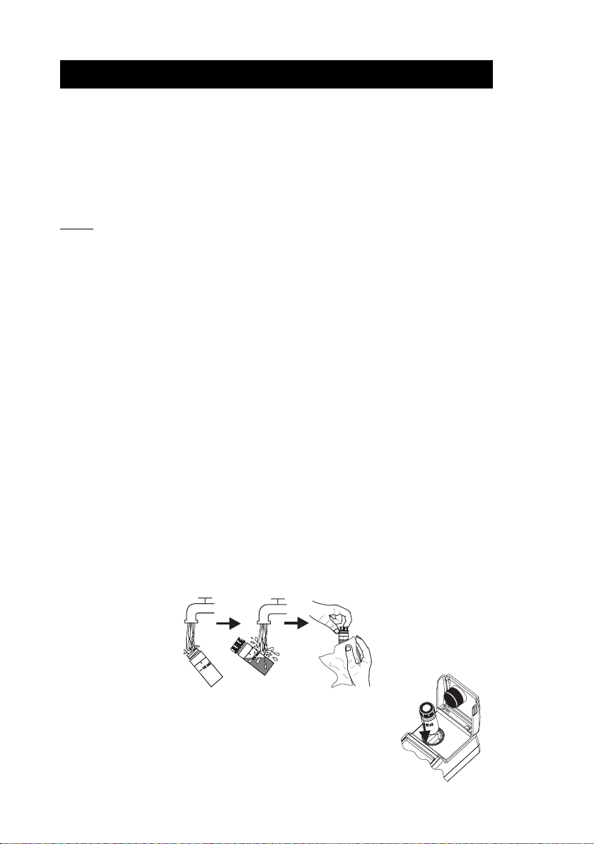
CUVET PREPARATION
Whenever a cuvet is used, it must be clean inside and outside. When it is placed into the
instrument, it must be dry outside, completely free of fingerprints or dirt.
If the cuvet is not indexed, put the cuvet with the factory mark aligned
with the sign on the instrument top.
14
Page 15
CUVET OILING (TURBIDITY only)
Warning: For colorimetric measurements the cuvet should be completely free of any trace of oil. Do not
use the oiling procedure for colorimetric measurements.
To hide minor imperfections and scratches, the cuvets should be oiled outside with the supplied silicone oil.
This is very important, especially for low turbidity samples (< 1 NTU), otherwise scratches can contribute
and alter turbidity readings.
The silicone oil has the same refractive index as the glass and will not alter the turbidity readings. It is
important to apply only a thin layer of silicone oil.
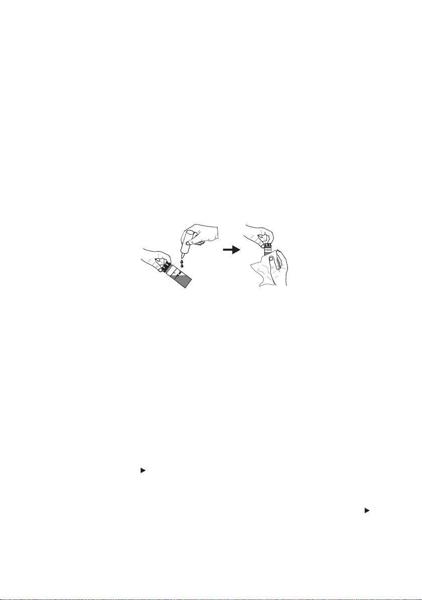
Warning: Do not apply silicone oil in excess because it may retain dirt or contaminate the cuvet
holder of the instrument, altering the turbidity readings.
It is very important to apply the silicone oil on a clean, dry cuvet. Apply a few drops of oil and wipe
the cuvet thoroughly with a lint-free cloth. Wipe off the excess oil till you obtain a thin, uniform
layer. If the procedure is correctly followed, the cuvet should appear nearly dry with no visible oil.
Note: The supplied cloth for oiling should be stored together with the silicone oil bottle and cuvets,
taking care to avoid contamination with dirt. After a few oiling procedures, the cloth will
contain enough oil to wipe the bottle with it without adding more oil. From time to time add
some drops of oil on the cuvet to provide the necessary oil quantity in the cloth.
INDEXING A CUVET
It is very important for low turbidity readings to always insert the cuvet into the instrument in the
same position.
All cuvets are factory indexed. This index can be used to put the cuvet with the factory mark on the
cuvet aligned with the sign on the instrument top.
To further reduce the effect of glass imperfections, the cuvet can be indexed and use this new index
as the position mark.
For indexing one cuvet or matching multiple cuvets, the continuous reading mode is suggested. In this
mode, if READ/TIMER
the lamp. After first reading is displayed, it is possible to open the cuvet lid and rotate the cuvet
without generating an error condition. The turbidity is immediately displayed, reducing considerably
the measurement time. The lamp of the instrument will turn off only when READ/TIMER is
released.
Note: The instrument can not perform continuous readings if the average mode is on.
is kept pressed, multiple successive readings are taken without turning off
15
Page 16
In order to index a cuvet follow the next steps:
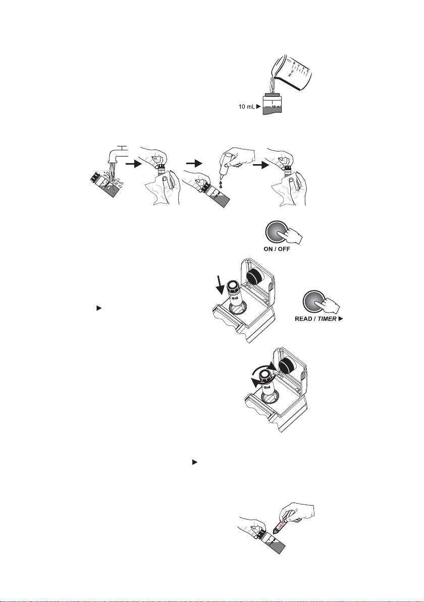
• Fill the cuvet with high quality water (<0.1 NTU)
up to the 10 mL mark.
• Clean and oil the cuvet as described before.
• Turn the instrument ON.
• Insert the cuvet into the instrument and press
READ/TIMER
. Record the reading.
• Open the instrument lid, slightly rotate the cuvet
and take a new reading.
• Repeat the last step until you read the lowest NTU
value. Alternatively, keep the READ/TIMER
pressed and, after the first value is displayed, open
the lid and start rotating the cuvet until the lowest
NTU value is displayed.
• Mark this position on the thicker white band on
the top of the cuvet with a water resistant pencil.
• Always use this position to align it with the
sign on the instrument top.
16
Page 17

MATCHING MULTIPLE CUVETS
Precise measurements require the use of a single cuvet. If it is not possible, cuvet selection and
matching must be performed before taking measurements.
In order to match multiple cuvets follow the next
steps:
• Fill some cuvets with high quality water
(<0.1NTU) up to the 10 mL mark.
• Clean and oil the cuvets as described before.
• Turn the instrument ON.
• Insert the first cuvet into the instrument and
press READ/TIMER
. Record the reading.
• Record the position of the cuvet and the
displayed reading.
• Mark this position on the thicker white band on
the top of the cuvet with a water resistant pencil.
• Insert the second cuvet into the instrument and
take a reading.
Page 18

• Open the instrument lid, slightly rotate the cuvet and take a new reading.
• Repeat the last step for the second cuvet until the reading is within 0.01 NTU of the value
obtained for the first cuvet.
• Alternatively, keep the READ/TIMER pressed and, after the first value is displayed, open the
lid and start rotating the cuvet until the read value matches the first cuvet.
• Mark this position on the second cuvet with a water resistant pencil.
• Follow the same procedure for all the cuvets you need.
Note: If the cuvet is indexed, use the index to position it in the instrument.
SAMPLING TECHNIQUE
When taking turbidity measurements it is very important to select a representative sample. For
consistent results, follow the next tips when sampling:
• Gently mix the water before taking the sample.
• If the sample is taken from a pipe, discard the first few liters.
• If measuring a non uniform source, collect samples from different places and mix them.
When measuring the collected sample, keep in mind the following:
• Samples should be analyzed immediately after collection because the turbidity can change in time.
• To avoid dilution of the sample it is better to rinse the cuvet with a quantity of sample and then
discard. Only after this you can fill the cuvet with sample.
• Pay attention that cold samples do not condense on the sample cell.
REMOVING AIR BUBBLES (TURBIDITY only)
Any air bubbles present in the sample will cause high turbidity readings. To obtain accurate
measurements, remove the air bubbles using one of these methods:
• Application of a partial vacuum;
• Addition of a surfactant, such as Triton X-100;
• Use of an ultrasonic bath;
• Heating the sample.
Sometimes it is necessary to combine two or more methods for efficient air bubble removal.
Note: Each method can alter the sample turbidity, if misused, so they have to be used with caution.
18
Page 19

APPLICATION OF VACUUM
Vacuum works by decreasing the atmospheric pressure. In this way the bubbles from the solution
came out to the surface.
Application of vacuum is a very simple procedure and can be applied with any vacuum source at hand.
The simplest equipment at hand is a syringe and a rubber stopper for vacuum degassing.
Notes: • Pay attention that the vacuum equipment be clean and oil-free.
• It is not recommended to apply vacuum to a viscous sample that contains volatile
components. In such cases the vacuum can determine the volatile component of the
viscous sample to increase the bubbles from the sample.
ADDITION OF SURFACTANT
Surfactant addition works by changing the surface tension of the water. In this way bubbles are
released from the sample. This method is effective in samples that are supersaturated with air.
The procedure consists in the addition of a drop of surfactant in the cuvet before adding the sample
to be analyzed.
A convenient surfactant to use for degassing is Triton X-100.
Warning: Pay attention that changing the surface tension will cause a rapid settling of particles that
cause turbidity. To avoid this problem, analyze as soon as possible the sample.
Do not shake vigorously the sample because the surfactant may foam. If you are using the same
cuvet, rinse it before adding a new sample in order to avoid surfactant accumulation.
Surfactant contribution to the turbidity readings is negligible.
Note: Surfactant addition should be used for degassing only when other methods are ineffective.
USE OF AN ULTRASONIC BATH
The ultrasonic waves are very effective in removing air bubbles from samples. However, ultrasonic
waves should be used with care because they can alter sample turbidity characteristics, by modifying
the shape and size of particles which cause turbidity. The ultrasonic waves can also break the existing
air bubbles, leading to a complication of the degassing process.
In order to avoid excess application of the ultrasonic waves you can apply ultrasound until all visible
air bubbles are removed, and then measure the sample turbidity. This is the most used procedure for
degassing.
If you are not sure that all air bubbles were removed, apply ultrasonic waves again for a short period
of time and then measure the turbidity. Repeat this procedure until the turbidity is increasing instead
of decreasing, sign that turbidity of the sample was altered.
In order to degas a sample fill a clean cuvet with sample and immerse it (1/2 to 2/3 immersed) in
an ultrasonic bath. Follow the degassing procedure described above. Only after the degassing
procedure is finished the cuvet can be capped.
19
Page 20

HEATING THE SAMPLE
Use of heat to remove air bubbles, although very effective in some cases, should be handled with care
because it can alter the turbidity of the sample. When heating a sample, the volatile components
from the sample can vaporize, the suspended components can dissolve or the sample characteristics
can change.
Therefore, the heating procedure should be used with extreme care.
The best way is to use a warm water bath and immerse the cuvet with sample into the bath. Heat the
sample only until the visible bubbles are removed.
Note: Always cool the heated sample to the original sample temperature before measurement.
The heating procedure can be used in combination with vacuum or ultrasonic waves application for
a more effective air bubble removal.
REAGENT ADDING (COLORIMETRY only)
• Because the reagent quantity is set up to react with 10mL of
sample is very important to fill the cuvet correctly. The liquid in
the cuvet forms a convexity on the top; the bottom of this convexity
must be at the same level with the 10 mL mark.
• To open the powder reagent pack:
a) use scissors to open the powder packet
b) push the edges of the packet to form a spout
c) pour the content of the packet
• Do not let the reacted sample to stand too long after reagent is added or accuracy will be lost.
• All the reaction times reported in this manual are reffered to 20ºC (68ºF). As a general rule of
thumb, they should be doubled at 10ºC (50ºF) and halved at 30ºC (86ºF).
• Insert the cuvet with the mark aligned with the mark on the instrument top.
• It is possible to take multiple readings in a row but it is recommended to take a new zero reading
for each sample and to use the same cuvet for zeroing and measurement.
• After the reading it is important to discard immediately the sample, otherwise the glass might
become permanently stained.
Note: In order to maximize accuracy, prior to a measurement follow the validation procedure, to
be sure that the instrument is properly calibrated. If necessary, calibrate the instrument.
20
Page 21

RANGE SELECTION
The HI 93414 instrument has three measurement ranges:
• Turbidity from 0.00 to 1000 NTU
• Free chlorine from 0.00 to 5.00 mg/L
• Total chlorine from 0.00 to 5.00 mg/L
At startup, the instrument shows for one second the range on the LCD.
The startup range is the last one used before turning off the instrument.
Before taking measurements check that the instrument is in the correct range or switch it to the
correct one.
• To switch between the existing ranges press
RANGE
The selected range will be briefly displayed on
the primary LCD and the instrument will enter in
the new range. The selection is circular, the total
chlorine range is followed by the turbidity range.
.
• If the current time is hidden, the selected
range is displayed on the secondary LCD as
“turb”, “F Cl” or “t Cl”.
• If the current time is displayed on the LCD a range
indication are the measuring units. For free and
total chlorine the units are mg/L and for turbidity
the units are NTU. In this case, when taking
measurements or calibrating the instrument, on
the secondary LCD the parameter is displayed as
“turb”, “F Cl” or “t Cl”.
21
Page 22

MEASUREMENT PROCEDURE
When taking turbidity, free or total chlorine measurements, several basic rules should be followed:
• Always use cuvets without scratches or cracks because they can cause inaccurate readings.
• Always cap the cuvets to avoid spillage of the sample into the instrument.
• Always close the lid of the instrument during measurement.
• Keep the lid of the instrument closed when it is not used to prevent dust or dirt entering.
• Always put the instrument on a flat, rugged surface when taking measurements.
• Do not operate in direct sunlight.
• Do not use too much oil to prevent contamination of the optical system (for turbidimeter range only).
TURBIDITY MEASUREMENTS
To take turbidity measurements, follow the next steps:
• Turn the instrument ON by pressing ON/OFF.
When dashes are displayed on the LCD, the
instrument is ready. The current time appears on
the secondary LCD, if selected in SETUP menu or
“turb” if the time is not displayed.
• Fill a clean, dry cuvet with 10 mL of sample up to the
mark, taking care to handle the cuvet by the top.
• Replace the cap.
• Wipe the cuvet thoroughly with a lint-free cloth
to remove any fingerprints, dirt or water spots.
• Apply silicone oil on the cuvet and wipe with a
lint-free cloth to obtain an even film over the
entire surface of the cuvet.
Note: It is very important to oil the cuvet, espe-
cially for low turbidity values (< 1 NTU)
to hide the glass imperfections which can
influence the reading.
• Place the cuvet into the instrument. Align the
mark from the cuvet with the sign on the
instrument top and close the lid.
Note: If you have a cuvet with orientation mark,
place the cuvet into the instrument with the
orientation mark aligned with the sign on
the instrument top.
22
Page 23
NORMAL MEASUREMENT
This type of measurement can be used for regular readings, when the sample is stable and normal
accuracy is required. In normal measurement mode, the lamp is ON for a minimum period of time
(about 7 seconds), saving the battery life. Normal measurement takes about 10 seconds.
If normal measurement is selected, the “AVG” tag will not be displayed.
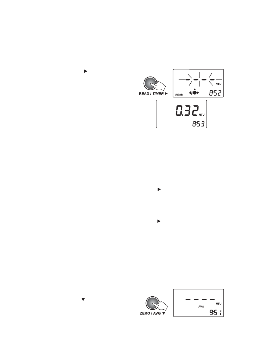
• Press READ/TIMER to start the measurement.
The display will show blinking dashes and the
icons for cuvet, detectors and lamp will appear
during measurement.
At the end of the measurement, the instrument
directly displays turbidity in NTU.
CONTINUOUS MEASUREMENT
This measurement mode can be used when many measurements have to be taken in a short period
of time. The feature is also useful to evaluate a very fast settling sample. This measurement mode
is recommended for indexing cuvets. After the first reading is taken, the lid opening will not generate
any errors.
The first value is displayed after about 10 seconds and then a new reading is displayed each second.
In order to take a continuous measurement keep READ/TIMER
measurements are taken. The display will show blinking dashes and the icons for cuvet, detectors
and lamp will appear. When a new value is displayed, the cuvet icon and the measurement unit will
briefly blink.
The last value remains on the display after the READ/TIMER is released.
pressed until the desired number of
AVERAGED MEASUREMENT
Select this measurement mode when samples that cause unstable readings are analyzed. By averaging
several readings, the random noise generated by the sample is reduced and accurate measurements
can be taken.
This mode can also be selected when high accuracy measurements are desired. In the average mode
10 measurements are averaged in a short period of time (about 20 seconds). The initial value is
displayed after 10 seconds and the display is updated every second with an intermediate value.
• To select the averaged measurement mode,
press ZERO/AVG
When this mode is selected, the AVG icon will
be displayed on the LCD.
.
23
Page 24

• Press READ/TIMER to start the average reading.
t
The display will show blinking dashes and
the icons for cuvet, detectors and lamp will
appear during measurement. When a new
intermediate value is displayed, the cuvet icon
and the measurement unit will briefly blink.
When the measurement is ended, the final
averaged result is displayed directly in NTU.
RANGE AND UNITS
HI 93414 automatically selects the correct turbidity
range to display the results with the highest accuracy.
If the measured value is higher than 1000 NTU
(over range), the display will show the maximum
value blinking.
The instrument has an EPA compliance reading
mode. If this feature is activated in SETUP, “EPA”
tag will appear on the LCD and the readings will be
rounded to meet EPA reporting requirements as
shown in the table.
UTN
0.1-0.0 50.0
01-1 1.0
04-01 1
001-04 5
004-001 01
0001-004 05
0001> 001
seraeNotdroceR
24
Page 25

FREE AND TOTAL CHLORINE MEASUREMENT
To take colorimetric measurements follow next steps:
• Turn the instrument on by pressing ON/OFF.
Assure that the correct range is selected by
paying attention to the startup message or to
the measuring units.
When dashes are displayed on the LCD, the
instrument is ready. The current time appears
on the secondary LCD, if selected in SETUP
menu, or “F Cl” or “t Cl” if the time is not
displayed.
The “ZERO” tag will blink suggesting that a
zero measurement should be done.
ZEROING THE INSTRUMENT
• Fill a clean, dry cuvet with 10 mL of sample,
up to the mark, taking care to handle the cuvet
by the top. Replace the cap.
• Wipe the cuvet thoroughly with a lint-free cloth
to remove any fingerprints, dirt or water spots.
• Place the cuvet into the instrument. Align the
mark on the cuvete with the sign on the
instrument top and close the lid.
Note:If you have a cuvet with orientation mark
place the cuvete with the orientation mark
aligned with the sign on the instrument top.
• Press ZERO/AVG . The dashes will blink on
the primary LCD. If the zeroing procedure was
successful, the display will show “-0.0-”.
25
Page 26

SINGLE SAMPLE READ
• Remove the cuvet from the instrument.
• Remove the cap.
• Add the content of one packet of the specific test
reagent, for:
Free Chlorine Total Chlorine
1 packet of or 1 packet of
HI 93701-0 HI 93711-0
• Replace the cap and shake gently for 20 seconds
(or 2minutes in case of seawater analysis).
• Replace the cuvet into the holder and ensure
that the mark on the glass is matched with the
mark on the instrument top. Close the lid.
• Hold READ/TIMER
will show the hourglass blinking and the
countdown prior to measurement.
Alternatively wait for:
Free Chlorine Total Chlorine
1 minute or 2 minutes and 30 seconds
and then just press READ/TIMER
In both cases blinking dashes will appear during
measurement.
The instrument directly displays the concentration
in mg/L of free or total chlorine.
Note:If the value is over range, the maximum
value (5.00 mg/L) will blink.
for 3 seconds. The display
.
or
26
Page 27

MULTIPLE SAMPLES READ
• Place the second cuvet with the reacted sample
into the holder and ensure that the mark on the
glass is matched with the mark on the instrument
top.
• Hold READ/TIMER
for 3 seconds. The display
will show the hourglass blinking and the
countdown prior to measurement.
Alternatively wait for:
Free Chlorine Total Chlorine
1 minute or 2 minutes and 30 seconds
and then just press READ/TIMER
.
In both cases blinking dashes will appear during
measurement.
The instrument directly displays the concentration
in mg/L of free or total chlorine.
Note:It is recommended to make a zero before
each measurement.
Note:If the signal to noise ratio is too high, the
zero value will blink.
INTERFERENCES
or
The colorimetric measurements are affected by the following interfering agents:
• Bromine (positive error).
• Chlorine dioxide (positive error).
• Iodine (positive error).
• Oxidized Manganese and Chromium (positive error).
• Alkalinity above 250 mg/L CaCO
or acidity above 150 mg/L CaCO
3
will not reliably develop the full
3
amount of color or it may rapidly fade. To resolve this, neutralize the sample with diluted HCl or NaOH.
• In case of water with hardness greater than 500 mg/L CaCO
, shake the sample for approximatively
3
2 minutes after adding the powder reagent.
27
Page 28

CALIBRATION PROCEDURE
TURBIDIMETER CALIBRATION
HI 93414 has a powerful calibration function that compensates for lamp aging or changing. The
calibration can be done using the suplied calibration solutions or user prepared standards.
HI 93414 turbidimeter is supplied with 4 AMCO standards –<0.1 NTU, 15 NTU, 100 NTU and 750
NTU. The Hanna standards are specially designed for this instrument. Turbidity standards have a shelf
life and should not be used after the expiration date.
Alternatively, formazin standards can be used. It is recommended that the turbidity value of the
prepared calibration solutions to be close to the default calibration points.
The first calibration point should be near 0 NTU, the second point can be chosen between 10 and
20 NTU, the third point between 50 and 150 NTU and the fourth point between 600 and 900 NTU.
FORMAZIN PREPARATION
In order to prepare formazin 4000 NTU stock solution, follow the next procedure:
Solution I : Dissolve 1.000 grams of hydrazine sulfate, (NH
water and dilute to 100 mL in a volumetric flask.
Warning: Handle hydrazine sulfate with care because it is a carcinogen reagent. Avoid inhalation,
ingestion, or skin contact.
Formazin solution can also contain some hydrazine traces.
Solution II : Dissolve 10.000 grams of hexamethylenetetramine, (CH2)
water and dilute to 100 mL in a volumetric flask.
Stock solution: Mix 10 mL Solution I and 10 mL Solution II in a flask. Let the stock solution stays
48 hours at 25±3°C (77±5°F). This will result in a 4000 NTU formazin suspension. It is very
important for the formation of the formazin polymer to maintain the same temperature.
The stock solution (4000 NTU) can be stored up to one year in proper conditions. Store formazin in
amber glass bottle or any UV-light blocking bottle.
To obtain a high quality formazin always use pure reagents and high-purity water.
To prepare the calibration standards, dilute the stock solution with the same high-purity water you
used for the preparation of the stock solution.
The diluted formazin solutions are not stable. They should be used immediately after preparation
and discard immediately after use.
CALIBRATION
For best results, the measurement techniques must be followed during calibration. If formazin
standards are used, mix the cuvets gently for about 1 minute and then allow the standard to settle for
1 more minute before calibration.
Calibration can be performed in two, three or four points. It is possible to interupt calibration
procedure at any time by pressing CAL/CHECK or ON/OFF.
, in distilled, deionized
2)2 H2SO4
6N4
, in distilled, deionized
Note: Calibration of the turbidity range will not affect the free or total chlorine measurements.
28
Page 29

TWO-POINT CALIBRATION
• Turn the instrument ON by pressing ON/OFF. If
you are not in turbidity range, first select the
range. If you are in turbidity range, when dashes
are displayed on the LCD, the instrument is
ready. The current time appears on the
secondary LCD, if selected in SETUP menu or
“turb”, if the time is not displayed.
• Enter calibration mode by pressing CAL/CHECK
for 3 seconds. The display shows “CAL P.1”on
the secondary LCD and no suggested value and
“READ” tag will blink.
• If the prepared formazin is used, edit the
displayed value by pressing UP or DOWN keys
until the display shows the correct value.
• Place the <0.1 NTU standard cuvet (or the
prepared one) into the holder and ensure that
the cuvet mark is aligned with the sign on the
instrument top.
Note: Alternatively, press CFM to skip the first
calibration point.
• Close the lid and press READ/TIMER
display will show blinking dashes and the icons
for cuvet, detectors and lamp will appear during
measurement.
• At the end of the measurement, the second
calibration point (15 NTU) is displayed on the
primary LCD and “CAL P.2” on the secondary LCD,
and “READ” tag will blink.
• Remove the first standard cuvet.
• Place the 15 NTU standard cuvet (or the second
prepared standard) into the holder, with the
cuvet mark aligned with the sign on the
instrument top.
. The
29
Page 30

• Close the lid and press READ/TIMER . The
display will show blinking dashes and the icons
for cuvet, detectors and lamp will appear during
measurement.
• At the end of the measurement, the third
calibration point (100 NTU) is displayed on the
primary LCD and “CAL P.3” on the secondary LCD
and “READ” tag will blink.
• At this moment it is possible to exit calibration
by pressing CAL/CHECK. The instrument will
memorize the two-point calibration data and
will return to measurement mode.
THREE-POINT CALIBRATION
To perform a three-point calibration, continue the
procedure with the following steps:
• Remove the second standard cuvet.
• Place the 100 NTU standard cuvet (or the third
prepared formazin standard) into the holder,
with the cuvet mark aligned with the sign on
the instrument top.
• Close the lid and press READ/TIMER
display will show blinking dashes and the icons
for cuvet, detectors and lamp will appear during
measurement.
• At the end of the measurement, the fourth
calibration point (750 NTU) is displayed on the
primary LCD and “CAL P.4” on the secondary LCD
and “READ” tag will blink.
• At this moment it is possible to exit calibration
by pressing CAL/CHECK. The instrument will
memorize the three-point calibration data and
will return to measurement mode.
. The
30
Page 31

FOUR-POINT CALIBRATION
To perform a four-point calibration, continue the
procedure with the following steps:
• Remove the third standard cuvet.
• Place the 750 NTU standard cuvet (or the fourth
prepared formazin standard) into the holder,
with the cuvet mark aligned with the sign on
the instrument top.
• Close the lid and press READ/TIMER
display will show blinking dashes and the icons
for cuvet, detectors and lamp will appear during
measurement.
• At the end of the measurement, the four-point
calibration is completed and the instrument returns
automatically to measurement mode.
OUT CAL RANGE FUNCTION
The instrument has an Out Cal Range function to
prevent taking measurements in a range where the
calibration do not assure the best results. The range
where the calibration assures correct measurements
is up to 40 NTU for a two-point calibration and up
to 150% of the third point value for a three-point
calibration.
The display will show a blinking “CAL” tag each
time the measurements are taken outside the
calibration range.
CALIBRATION ERROR MESSAGES
• If the value of the standard read during the
calibration is too far from the set value, the
instrument will display “-LO-” or “-HI-” error
messages. Check if the correct standard is used or
prepare a fresh standard, if formazine is used, and
repeat the reading of the standard.
. The
31
Page 32

• If the calculated calibration coefficients are outside
a certain range the “CAL Err” message is displayed.
CALIBRATION DELETION
HI 93414 is factory calibrated. It is possible to
restore factory calibration by deleting the last
performed calibration.
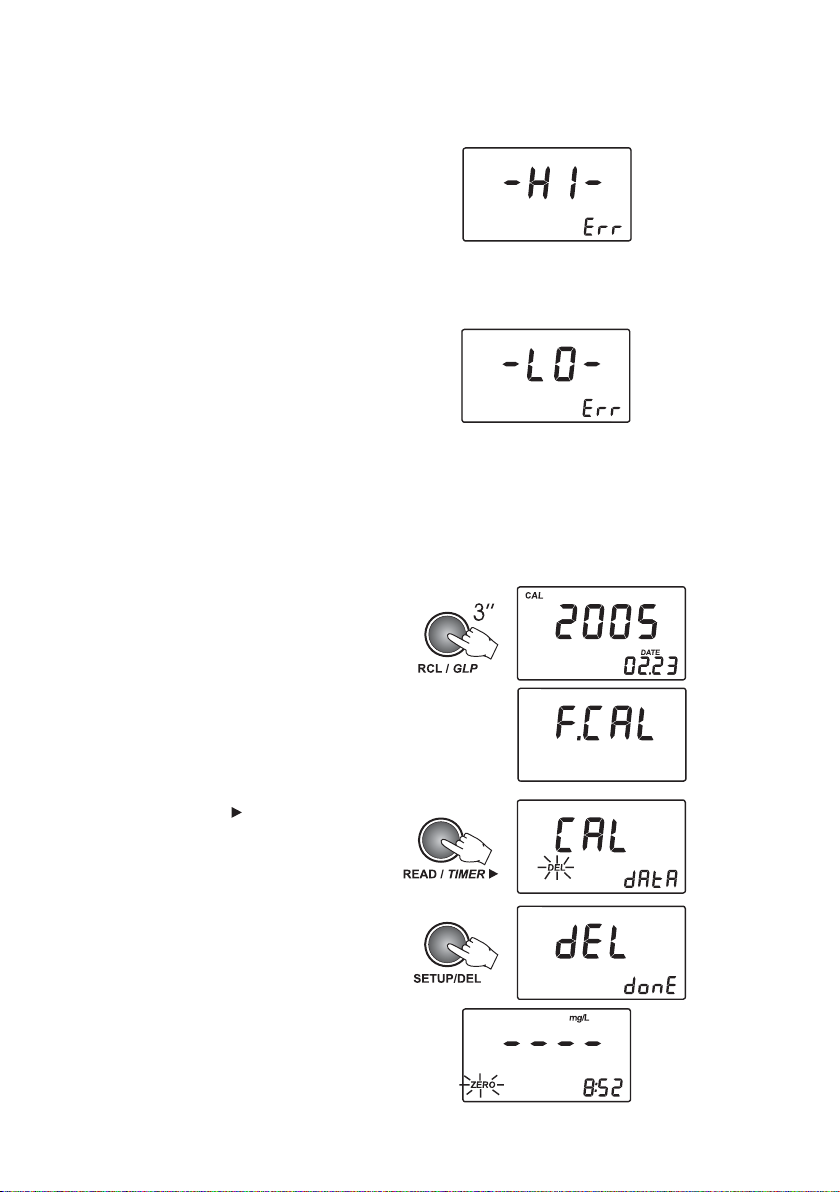
To delete last calibration, follow the next steps:
• Enter the GLP feature by pressing RCL/GLP for
three seconds.
The date of the last calibration will be displayed
on the LCD.
• Press READ/TIMER
related to calibration. The last panel is the one
with delete calibration.
• Press SETUP/DEL to delete the current calibration.
The instrument will display “del done” for a second
and the calibration is deleted, then the instrument
will automatically return to measurement mode.
to see the information
32
Page 33

COLORIMETER CALIBRATION
The HI 93414 free and total chlorine colorimeter has a powerful CAL CHECK function that allows the
user to check the instrument calibration against a NIST traceable standard before making a set of
measurements. With the same standard, the instrument could be re-calibrated, if necessary.
Note:Free and total chlorine must be calibrated separately. Calibration of one range will not
calibrate the other range.
VALIDATION PROCEDURE
Warning: Do not validate or calibrate the instrument with standard solutions other than Hanna CAL
CHECK™ Standards, otherwise erroneous results will be obtained. For accurate validation
and calibration please perform test at room temperature, 18 to 25ºC (64.5 to 77.0ºF).
• Turn the instrument on by pressing ON/OFF.
Make sure that the instrument is in the free or
total chlorine range (the desired one).
• Press RANGE
(free or total chlorine). When dashes appear
on the LCD, the instrument is ready. The “ZERO”
tag will blink on the LCD.
• Place the zero cuvet (A) in the instrument with the
mark aligned with the mark on the instrument top.
• Close the lid and press ZERO/AVG . The LCD
will display blinking dashes and the measuring
icon during zero measurement.
At the end of zero measurement the “-0.0-” is
displayed. The meter is now ready for validation.
to select the desired range
33
Page 34

• Remove the cuvet.
• Place the CAL CHECK™ Standard cuvet B into
the holder. Make sure that the mark on the
glass is aligned with the mark on the instrument
top.
• Press CAL/CHECK. The LCD will display blinking
dashes and the measuring icon during check
measurement.
After a few seconds the display will show the
validation standard value.
Note:The reading should be within specifications as reported on the CAL CHECK™ Standard Certificate.
If the value is found out of specifications, please check that the cuvets are free of fingerprints, oil
or dirt and repeat validation. If results are still out of specifications, then recalibrate the instrument.
CALIBRATION PROCEDURE
To calibrate the free or total chlorine range of the HI 93414 the provided standard solution must be
used. Do not calibrate the instrument with standard solutions other than Hanna CAL CHECK™
Standards, otherwise erroneous results will be obtained. For accurate calibration please perform test
at room temperature, 18 to 25ºC (64.5 to 77.0ºF).
To calibrate one range follow next steps:
• Turn the instrument ON by pressing ON/OFF.
Make sure that the instrument is in the free or
total chlorine range (the one you want to use).
• Press RANGE
(free or total chlorine). When dashes appear
on the LCD, the instrument is ready. The current
time will be displayed on the secondary LCD, if
selected in SETUP menu. If not, “F Cl” or “t Cl”
will be displayed, depending on the selected
range.
The “ZERO” tag will blink on the LCD.
to select the desired range
34
Page 35

• Press and hold CAL/CHECK for 3 seconds to enter
calibration.
The LCD will show “CAL” tag and the parameter
for which the calibration is performed.
• Place the CAL CHECK™ Standard Cuvet A into
the holder and ensure that the mark on the cuvet
is aligned with the mark on the instrument top.
• Close the lid and press ZERO/AVG
The LCD will display blinking dashes and the
measuring icon during zero measurement.
At the end of the zero measurement, “-0.0-” is
displayed.
The “READ” tag will blink.
• Remove the cuvet.
• Place the CAL CHECK™ Standard Cuvet B into
the holder. Make sure that the mark on the
cuvet is aligned with the mark on the instrument
top.
• Close the lid and press READ/TIMER
The instrument will show blinking dashes and
the measuring icon during measurement.
At the end, the value of the CAL CHECK™
standard value (1.00 mg/L) is displayed for
one second and then “Stor” to confirm that the
new calibration data has been accepted.
.
.
The meter automatically enters in measurement
mode.
35
Page 36
CALIBRATION ERROR MESSAGES
• The calibration is successfully performed if the
CAL CHECK™ readings is in certain limits.
If the CAL CHECK™ standard value is too high,
the display will show “-HI-” on the primary
display and “Err” on the secondary display. If
this message appears, check if the correct cuvet
was used.
• If the CAL CHECK™ standard value is too low,
the display will show “-LO-” on the primary
display and “Err” on the secondary display. If
this message appears, check if the correct cuvet
was used.
CALIBRATION DELETION
HI 93414 is delivered factory calibrated. It is possible to restore factory calibration at any time if the
user calibration do not work as expected.
Note: Deleting the user calibration for one range will not affect the other ranges.
To delete last calibration, follow next steps:
• Enter the GLP feature by pressing RCL/GLP for 3
seconds.
The date of the last calibration will be displayed
on the LCD.
If no calibration was performed, the “F.CAL”
message appears on the LCD and the instrument
returns to measurement mode.
• Press READ/TIMER
related to calibration. The last panel is the one
with delete calibration.
• Press SETUP/DEL to delete the current calibration.
The instrument will restore the factory calibration
and will automatically return to measurement
mode.
to see the information
36
Page 37

LOGGING
HI 93414 has a logging memory of 200 records. The log memory is unique for all ranges. The
records are stored in chronological order. With each measurement, the range, date, time, and tag ID
are stored. In this way, each record is fully characterized and can be easily analyzed when downloading
on the PC application (HI 92000).
LOGGING
The log function is active only after a valid measurement
is obtained (no errors).
• To log a value, press LOG/CFM when the measurement
result is displayed.
The instrument asks to READ TAG for identification
of the sampling location. The number for the new
record is also displayed on the secondary LCD.
• To read the ID code for the sampling location
identification, simply touch the
the matching connector, located on the back of
the instrument (see page 10, “Connectors
Description”). Alternatively, press again LOG/CFM
to store the record without the tag ID code.
• If the tag is successfully read, the instrument will
beep once, displaying the unique hexadecimal
code of the tag, and store the data.
After data is stored, the instrument returns to
measurement mode.
Notes: • If the tag is not read within 20 seconds,
the logging procedure is canceled.
• A measurement can be stored only once.
Also an over range value can be stored.
• If less than ten free records are available, the
“LOG” tag will blink while storing data.
iButton
®
tag with
or
or
• If the log memory is full, the “LoG FULL”
message appears for two seconds on the LCD
and the instrument returns to measurement
mode without storing the new record.
To store a new record, delete one or more records.
37
Page 38

VIEW LOGGED DATA
The stored records can be viewed at any moment by
pressing RCL/GLP. To return to normal measurement
mode press RCL/GLP again.
LOG SEARCHING
The log records are stored in chronological order.
The first displayed record is the last stored one.
• Press UP or DOWN keys to scroll the log memory
record by record. By keeping pressed the UP or
DOWN keys, the scrolling speed will increase.
The scrolling of the log is possible from any
panel of the record, except “Delete last log”
and “Delete all logs” panels.
• When scrolling the log, the record number is
displayed for one second on the secondary LCD,
together with “TAG”, if the identification of
the sampling location was made. After this,
the range is displayed on the secondary LCD as
“turb”, “F.Cl” or ”t.Cl”.
When the end of the log is reached, a long
beep will be heard.
RECORD VIEWING
Each record contains more information than the
measured value. The additional information is
grouped in several panels.
Press READ/TIMER
panels. The record panels are displayed one by
one in a circular way.
Each record contains the following panels:
• The record value (turbidity, free or total chlorine
value) and range.
Note: If the logged sample value is an over range
reading, the maximum value will be displayed
blinking.
• The hexadecimal string of the tag for the sampling
location ID.
Note: If the ID data is missing, dashes are displayed
instead.
to scroll through the record
38
Page 39

• Measurement date in YYYY.MM.DD format.
• Measurement time in hh:mm format.
• Delete the last record panel (only for last
record).
• Delete all records.
DELETE LAST RECORD
To log other values, the last record or all records
have to be deleted.
• To delete the last record, press SETUP/DEL while
in delete last records panel.
• The instrument asks for confirmation and if
LOG/CFM is pressed, the last record is deleted.
To abort the delete function, press READ/TIMER
instead of LOG/CFM.
• After the record is deleted, the instrument enters
immediately in the first panel of the previous
record. If the log becomes empty, dashes will
be displayed for one second on the LCD and the
instrument will return to idle mode.
DELETE ALL RECORDS
To delete all records, scroll the log until delete all
records panel is displayed on the LCD.
• To delete all records press SETUP/DEL while in
delete all records panel.
39
Page 40

• The instrument asks for confirmation and if
LOG/CFM is pressed, all records are deleted. To
abort the delete function, press READ/TIMER
instead of LOG/CFM.
• After all records are deleted, dashes are displayed
for one second on the LCD and the instrument
returns to measurement mode.
GOOD LABORATORY PRACTICE (GLP)
The GLP feature allows the user to view last calibration data. Also, the user calibration can be deleted.
• Press and hold RCL/GLP for 3 seconds to enter/exit
GLP data consulting.
Several functions are available when in GLP menu.
• Press READ/TIMER
to scroll the following
GLP data:
• The last calibration date, in YYYY.MM.DD
format. If no calibration was performed, the
factory calibration message, “F.CAL”, will be
displayed on the LCD.
• The time of the last calibration in hh:mm
format.
• First calibration point - only for turbidimeter
range. The displayed value is 0.00 NTU if the
first calibration point was skipped or the real
read value will appear.
• Second calibration point - only for turbidimeter
range.
or
or
40
Page 41

• Third calibration point - only for turbidimeter
range (if available).
• Fourth calibration point - only for turbidimeter
range (if available).
• Delete calibration panel.
To delete last calibration:
• Press SETUP/DEL while in the delete calibration
panel of the GLP.
The user calibration will be deleted and the
factory calibration will be restored.
The instrument will enter automatically in
measurement mode.
41
Page 42

SETUP
Setup mode allows viewing and modifying the instrument parameters.
The blinking “CAL” tag during setup mode suggest to press CAL/CHECK for parameters editing.
• To enter/exit SETUP, press SETUP/DEL.
• To select the parameter to be edit, press UP or
DOWN keys until the desired panel is displayed.
Press UP or DOWN keys also to change the
value of a parameter.
• To start/stop editing a parameter, press CAL/
CHECK.
• To save the new selected value of a parameter,
press LOG/CFM.
SET EPA COMPLIANCE MODE (for turbidimeter range only)
When EPA compliance reading is ON, “EPA” tag is displayed on the LCD and the reported values are
rounded to meet EPA reporting requirements.
• To start edit the EPA mode, press CAL/CHECK
when EPA compliance reading panel is displayed.
The parameter setting and “CFM” tag will start
blinking.
• Press the UP or DOWN keys to set ON or OFF
the EPA compliance mode.
• Press LOG/CFM to save the setting. The new
selected option of the parameter will be
displayed on the LCD.
Alternatively, press CAL/CHECK to exit without
saving the new settings.
42
Page 43

SET BEEPER
The HI 93414 has a built in beeper that signals the tag read, the key press and the error conditions.
The beeper can be selected to be ON or OFF.
• To set the beeper ON/OFF, press CAL/CHECK
when set beeper panel is displayed.
The beeper status and “CFM” tag will start
blinking.
• Press the UP or DOWN keys to set the beeper
ON/OFF.
• Press LOG/CFM to save the change. The new
selected option will be displayed on the LCD.
Alternatively, press CAL/CHECK to exit without
saving the changes.
SHOW / HIDE THE TIME
You can choose between showing or hiding the
current time on the LCD.
• To set hiding or showing the time, press CAL/
CHECK when show/hide time panel is displayed.
The time show status and “CFM” tag will start
blinking.
• Press the UP or DOWN keys to set lcd / hide for
time.
• Press LOG/CFM to save the change. The new
selected option will be displayed on the LCD.
Alternatively, press CAL/CHECK to exit without
saving the changes.
SET THE DATE
The HI 93414 turbidimeter has a built-in real time clock (RTC). The RTC time is used to generate
a unique time stamp for each recorded value and to automatically store the last calibration date. The
current time can be displayed on the LCD when the instrument is in idle mode.
43
Page 44

• To set the current date, press CAL/CHECK when
set date panel is displayed. The date format is
YYYY.MM.DD. The last two digits of the year
value and “CFM” tag will start blinking.
• Press the UP or DOWN keys to set the year
value.
• Press LOG/CFM or READ/TIMER
editing the month value. The month value will
start blinking.
• Press the UP or DOWN keys to set the month
value.
• Press LOG/CFM or READ/TIMER
editing the day value. The day value will start
blinking.
• Press the UP or DOWN keys to set the day
value.
Note: To edit the year again, after the day was
edited, press READ/TIMER
• Press LOG/CFM to save the new date. The new
set date will be displayed. Alternatively, press
CAL/CHECK to exit without saving the changes.
SET THE TIME
to start
to start
.
• To set the current time, press CAL/CHECK when
set time panel is displayed. The time format is
hh:mm. The hour value and “CFM” tag will
start blinking.
44
Page 45

• Press the UP or DOWN keys to set the hour
value.
• Press LOG/CFM or READ/TIMER
editing the minutes. The minutes value will
start blinking.
• Press the UP or DOWN keys to set the minutes
value.
Note: To edit the hour again, after the minutes
were edited, press READ/TIMER
• Press LOG/CFM to save the new time. The new
set time will be displayed.
Alternatively, press CAL/CHECK to exit without
saving the changes.
SET INSTRUMENT ID
The instrument ID is a four digit number that can be edited by the user. The instrument ID is
downloaded on the PC application, together with the logged data. By setting a different ID for each
instrument it is possible to mix information from many turbidimeters into the same database.
• To set the instrument ID, press CAL/CHECK when
set instrument ID panel is displayed.
The default instrument ID is 0000. The existing
ID value and “CFM” tag will start blinking.
to start
.
• Press the UP or DOWN keys to set the new
instrument ID. By pressing and holding the UP
or DOWN keys, the speed will increase.
• Press LOG/CFM to save the change. The new
instrument ID will be displayed.
Alternatively, press CAL/CHECK to exit without
saving the changes.
45
Page 46

SET BAUD RATE
The HI 93414 has a RS232 and a USB link. When the USB connection is used, the RS232
connection becomes inactive.
To successfully communicate with the PC, the same baud rate must be selected on the instrument and
on the PC application. The available baud rates are 1200, 2400, 4800 and 9600.
• To set the baud rate, press CAL/CHECK when set
baud rate panel is displayed. The parameter
value and “CFM” tag will start blinking.
• Press the UP or DOWN keys to select the new
baud rate value.
• Press LOG/CFM to save the change. The new
selected baud rate will be displayed.
Alternatively, press CAL/CHECK to exit without
saving the changes.
LCD BACKLIGHT
The LCD can be illuminated to allow the user to see the readings even in
dark environments.
To turn ON/OFF the backlight, press LIGHT.
The backlight will automatically shut-off after 25 seconds of non-use to
save the battery life.
46
Page 47

TAG INSTALLATION
The tag is housed in a rugged metal that can withstand harsh environments. However, it is better
to protect the tag from direct rain.
Place the tag near a sampling point. Fix it securely with the provided screws, in such a way that the
metallic
iButton® is easily accessible for reading the tag.
The number of tags that can be installed is practically unlimited. Additional tags can be ordered
(HI 920005 - five tag holders with tags).
LAMP REPLACEMENT
The instrument tungsten lamp has a life longer than 100,000 measurements. In case of lamp
failure, the defective lamp can be easily replaced. When the lamp is broken, the instrument displays
“no L” error message.
To replace the lamp follow the next steps:
• Remove the battery lid.
• Unscrew the lamp connection using a
screwdriver.
• Unlock the lamp and extract it by pulling it out
from the lamp holder handler.
• Place the new lamp in the right position and
push it until is securely locked.
• Insert the lamp leads into the connector and
tight them using a screwdriver.
Warning: After lamp replacement the meter has
to be recalibrated.
47
Page 48

BATTERIES MANAGEMENT
For field measurements, HI 93414 is powered by 4 x 1.5V AA
batteries. The battery life is enough for 1500 normal measurements.
When the instrument is started, the remaining battery life is
estimated and reported in percents.
To preserve the battery it is better to use normal instead of
averaged measurements. Continuous measurements keep the lamp
on and should be used with caution if the battery life is an issue.
To further save the battery life, the instrument will turn off after
15 minutes of non-use. The backlight will be turn off after 25
seconds since the last key was pressed.
The battery life is measured each time the lamp is turned on and
if the remaining battery life is less than 10%, the blinking
battery tag will be displayed on the LCD to warn the user that the
batteries need to be replaced.
When the batteries are completely discharged, “0% bAtt” message
will be displayed on the LCD for one second and the instrument
will turn off.
In order to use the instrument again, replace the batteries with
new ones or use an AC adapter.
BATTERIES REPLACEMENT
To replace the batteries follow the next steps:
• Press ON/OFF to turn OFF the instrument.
• Open the batteries cover by pressing the locking clip.
• Take out the used batteries and insert 4 new 1.5V AA size batteries, while paying attention to the
correct polarity as indicated on the battery compartment.
48
Page 49

• Replace the cover and press it until it locks.
• Turn the instrument ON.
Warning: Replace batteries only in a non-hazardous area.
USING AN AC ADAPTER
The HI 93414 can be powered from the AC adapter when used in laboratory. See the Accessories
section to select the correct AC adapter.
To power the instrument, simply connect the AC adapter to the instrument (see page 10, “Connectors
Description”).
It is not necessary to turn the instrument off when connecting the external adapter.
Note: The connection to the external adapter will not recharge the batteries.
49
Page 50

PC INTERFACE
To fully use the instrument tag identification system function, the measured data has to be
downloaded to a computer. The instrument can use RS232 or USB connection to communicate
with the PC.
When using the RS232 protocol, simply connect a HI 920011 serial cable between the
instrument and the computer.
To use the USB protocol, simply connect a regular USB cable between instrument and PC.
In both cases, the PC must run the HI 92000 application for successful data transfer.
ERROR CODES
HI 93414 has a powerful diagnostic system. The common errors are detected and reported for
easy diagnostic and maintenance.
RORRE NOITPIRCSED NOITCA
;3rrE–1rrE
8rrE;7rrE;6rrE
4rrE
PAC .desolctonsidilehT
Lon .thgilonronekorbpmaL
oLL .thgilhguonetoN
iHL .thgilhcumooT
-OL-
-IH-
vnI .detrevnierasdradnatsnoitarbilaC
gniknilbgatyrettaB .wolootsiefilyrettabgniniamerehT .seirettabecalpeR
ttAb
.srorrelacitirC
.nwodstuhsdnaspeebtnemurtsniehT
dnaeciwtyltrohsspeebtnemurtsniehT
.sdnoces01retfanwodstuhs
tnerrucrofdesudradnatsehT
.wolootsitniopnoitarbilac
tnerrucrofdesudradnatsehT
.hgihootsitniopnoitarbilac
rofdegrahcsidooteraseirettabehT
.stnemerusaemtcerroc
ecivresannaHllaC
PUylsuoenatlumissserP
ehtteserotNWODdna
.stnetnocMORPEE
.dilehtesolC
nruter,stsisreprorreehtfI
.tnemurtsnieht
kcehC.pmalehtecalpeR
rofmetsyslacitpoeht
.snoitcurtsbo
metsyslacitpoehtkcehC
.snoitcurtsborof
metsyslacitpoehtkcehC
.snoitcurtsborof
dnadradnatsehtkcehC
.enotcerrocehtesu
dnadradnatsehtkcehC
.enotcerrocehtesu
dnadradnatsehtkcehC
.enotcerrocehtesu
.seirettabecalpeR
50
Page 51

ACCESSORIES
REAGENT SETS
TM
HI 93414-11 CAL CHECK
HI 93701-01 Reagents for 100 Free Chlorine tests
HI 93701-03 Reagents for 300 Free Chlorine tests
HI 93703-58 Silicon oil (15 mL)
HI 93711-01 Reagents for 100 Total Chlorine tests
HI 93711-03 Reagents for 300 Total Chlorine tests
HI 98703-11 Calibration set for turbidimeter(<0.1, 15, 100 and 750 NTU)
OTHER ACCESSORIES
HI 710005 Voltage adapter from 115V to 12 Vdc (USA plug)
HI 710006 Voltage adapter from 230V to 12 Vdc (European plug)
HI 710012 Voltage adapter from 240V to 12 Vdc (UK plug)
HI 710013 Voltage adapter from 230V to 12 Vdc (South Africa plug)
HI 710014 Voltage adapter from 230V to 12 Vdc (Australia plug)
HI 731318 Tissue for wiping cuvets (4 pcs.)
HI 731331 Glass cuvets (4 pcs.)
HI 731335N Caps for cuvets (4 pcs.)
HI 740027P 1.5V AA battery (12 pcs.)
HI 740234 Replacement lamp for EPA turbidimeter (1 pcs.)
HI 92000 Windows
HI 920005 5 tag holders with tags
HI 920011 5 to 9 pins RS232 connection cable
HI 93703-50 Cuvets cleaning solution (230 mL)
Calibration set for Free & Total Chlorine (1 set)
®
compatible software
RECOMMENDATIONS FOR USERS
Before using this product, make sure that it is entirely suitable for your specific application and
for the environment in which it is used.
Operation of this instrument may cause unacceptable interferences to other electronic equipments,
requiring the user to follow all necessary steps to correct interferences.
Any variation introduced by the user to the supplied equipment may degrade the instrument’s
EMC performance.
To avoid damage or burns, do not put the instrument in microwave ovens. For your own and the
instrument safety do not use or store the instrument in hazardous environments.
Hanna Instruments reserves the right to modify the design, construction and appearance of its
products without advance notice.
51
Page 52

SALES AND TECHNICAL SERVICE CONTACTS
Australia:
Tel. (03) 9769.0666 • Fax (03) 9769.0699
China:
Tel. (10) 88570068 • Fax (10) 88570060
Egypt:
Tel. & Fax (02) 2758.683
Germany:
Tel. (07851) 9129-0 • Fax (07851) 9129-99
Greece:
Tel. (210) 823.5192 • Fax (210) 884.0210
Indonesia:
Tel. (210) 4584.2941 • Fax (210) 4584.2942
Japan:
Tel. (03) 3258.9565 • Fax (03) 3258.9567
Korea:
Tel. (02) 2278.5147 • Fax (02) 2264.1729
Malaysia:
Tel. (603) 5638.9940 • Fax (603) 5638.9829
Singapore:
Tel. 6296.7118 • Fax 6291.6906
South Africa:
Tel. (011) 615.6076 • Fax (011) 615.8582
Taiwan:
Tel. 886.2.2739.3014 • Fax 886.2.2739.2983
Thailand:
Tel. (662) 619.0708 • Fax (662) 619.0061
02/06
United Kingdom:
Tel. (01525) 850.855 • Fax (01525) 853.668
USA:
Tel. (401) 765.7500 • Fax (401) 765.7575
For e-mail contacts and a complete list of Sales and Technical offices, please see
www.hannainst.com.
52
MAN93414
 Loading...