

Page 1
Instruction Manual
95mm MIN
3.74"
76mm
3"
0.25/4mm
0.01/0.160"
79mm
3.11"
ADJUSTABLE
LOCATION
BRACKET
HI 933700
Panel-Mounted
µS/cm Controller
Dear Customer,
Thank you for choosing a Hanna product. This manual will
provide you with the necessary information for correct operation of the instrument. Please read it carefully before using
the product. If you need additional technical information, do
not hesitate to e-mail us at tech@hannainst.com.
These instruments are in compliance with
directives
EN 50081-1 and EN 50082-1.
PRELIMINARY EXAMINATIONPRELIMINARY EXAMINATION
PRELIMINARY EXAMINATION
PRELIMINARY EXAMINATIONPRELIMINARY EXAMINATION
FUNCTIONAL DESCRIPTIONFUNCTIONAL DESCRIPTION
FUNCTIONAL DESCRIPTION
FUNCTIONAL DESCRIPTIONFUNCTIONAL DESCRIPTION
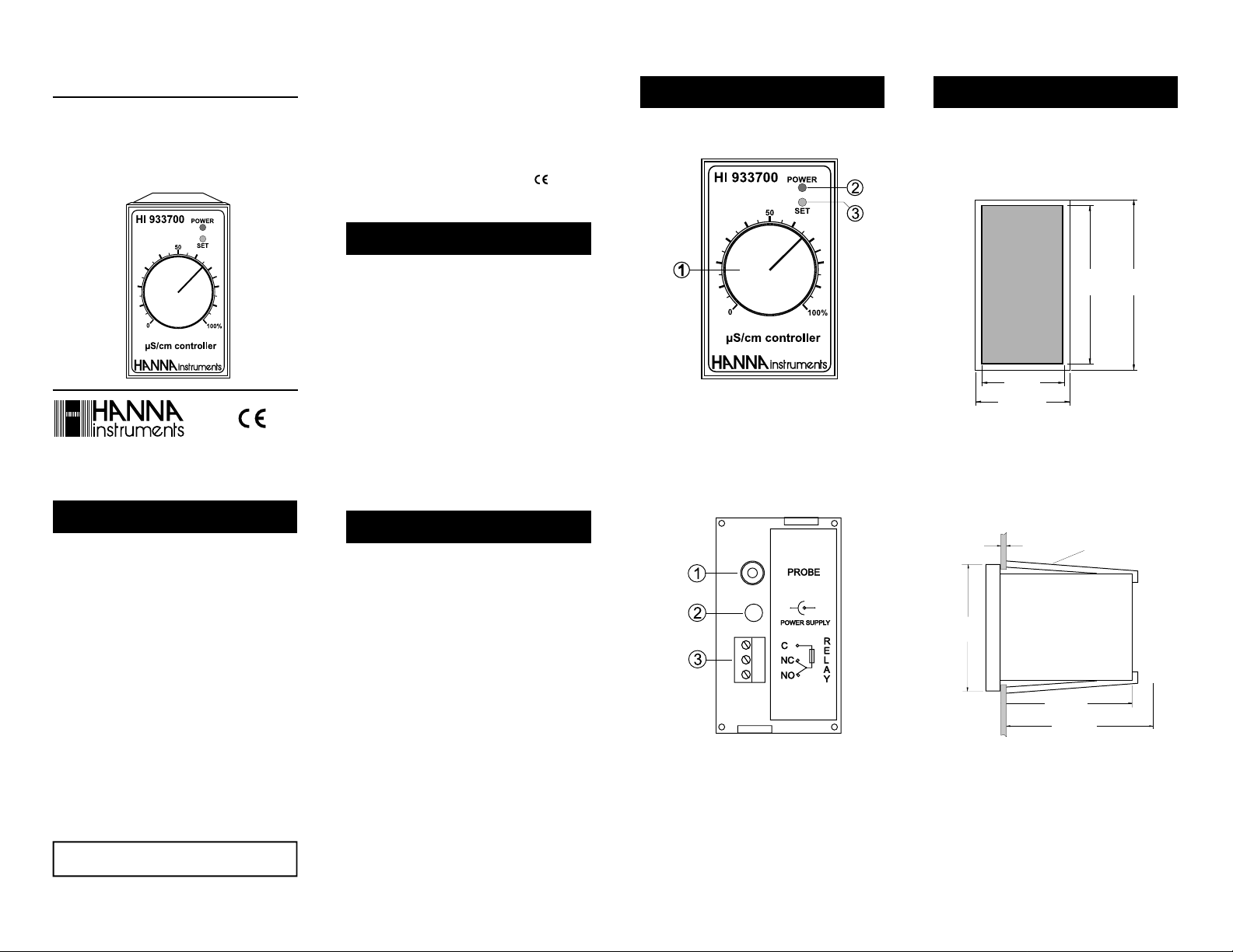
FRONT PANEL
MECHANICAL DIMENSIONSMECHANICAL DIMENSIONS
MECHANICAL DIMENSIONS
MECHANICAL DIMENSIONSMECHANICAL DIMENSIONS
MECHANICAL DIMENSIONSMECHANICAL DIMENSIONS
MECHANICAL DIMENSIONS
MECHANICAL DIMENSIONSMECHANICAL DIMENSIONS
MECHANICAL DIMENSIONS
FRONT VIEW OF THE PANEL-MOUNTED UNIT.
Dimensions show the cutout size for the installation and also
the outside dimensions of the panel.
This Instrument is in
http://www.hannainst.com
WARRANTYWARRANTY
WARRANTY
WARRANTYWARRANTY
HI 933700 controller is warranted for two years against defects
in workmanship and materials when used for their intended purpose
and maintained according to instructions. The probes are warranted
for a period of one year. This warranty is limited to repair or replacement free of charge.
Damages due to accident, misuse, tampering or lack of prescribed
maintenance are not covered.
If service is required, contact the dealer from whom you purchased the
instrument. If under warranty, report the model number, date of purchase, serial number and the nature of the failure. If the repair is not
covered by the warranty, you will be notified of the charges incurred. If
the instrument is to be returned to Hanna Instruments, first obtain a
Returned Goods Authorization Number from the Customer Service department and then send it with shipment costs prepaid. When shipping
any instrument, make sure it is properly packaged for complete protection.
To validate your warranty, fill out and return the enclosed warranty card
within 14 days from the date of purchase.
All rights are reserved. Reproduction in whole or in part is prohibited
without the written consent of the copyright owner, Hanna Instruments Inc., Woonsocket, Rhode Island, 02895 , USA.
Hanna Instruments reserves the right to modify the design, construction
and appearance of its products without advance notice.
Compliance with the CE Directives
Remove the instrument from the packing material and
examine it carefully. If any damage has occurred during
shipment, immediately notify your Dealer or the nearest
Hanna Customer Service Center.
The meters are supplied with:
• HI 7682 EC probe;
• Mounting brackets;
• HANNA power adapter.
Note:Conserve all packing material until the instrument has
been observed functioning correctly. Any defective item
must be returned in its original packing.
GENERAL DESCRIPTIONGENERAL DESCRIPTION
GENERAL DESCRIPTION
GENERAL DESCRIPTIONGENERAL DESCRIPTION
The HI933700 series instruments are panel-mounted controllers designed for simplicity of use in a wide range of
industrial applications.
The models are designed with a large setting knob on the
front panel and two indication LEDs. Power supply and relay
connections are made via the plug-in terminal blocks on the
rear panel.
The instruments are equipped with a probe connection socket
and accept input direct from an EC probe.
Another feature is the selectable output relay contact configuration NC (Normally Closed) or NO (Normally Open).
1. Setting knob
2. Green power LED
3. Red alarm LED
REAR PANEL
1. RCA for the EC probe
2. Power socket
3. Output relay contacts
C = Central contact
NO = Normally Open
NC = Normally Closed
42mm
1.65"
49mm
1.93"
73mm
2.87"
79mm
3.11"
SIDE VIEW OF THE PANEL-MOUNTED UNIT.
Adjustable location brackets (supplied with the meter) allow
the controller to slide into the cutout and will hold the unit
securely in place. 95 mm (3.74") is the minimum amount of
space required to install the controller with the cables
connected.
Page 2
SPECIFICATIONSSPECIFICATIONS
SPECIFICATIONS
SPECIFICATIONSSPECIFICATIONS
HI933700
Range 0 to 2000 µS/cm (HI 933700/1, HI933700/2);
0 to 4000 µS/cm (HI 933700/3, HI933700/4).
Accuracy (@ 20°C/68°F) ±5% f.s.
Setpoint Adjustable from 0 to 100% f.s.
Setpoint Hysteresis ±10% f.s.
Alarm Red LED lit if EC value exceeds SP (/1, /3)
Red LED lit if EC value is lower than SP (/2, /4)
Calibration Manual with one trimmer
Probe HI 7682 EC probe (included)
Power supply HANNA Power Adapter (included)
Dimensions 79 x 49 x 95 mm (3.11 x 1.93 x 3.74”)
Weight 150 g (5.3 oz.)
Installation cat. II
Output relay 1A max resistive load;
0.75 A max. inductive load; 250 VAC
INITIAL PREPARATIONINITIAL PREPARATION
INITIAL PREPARATION
INITIAL PREPARATIONINITIAL PREPARATION
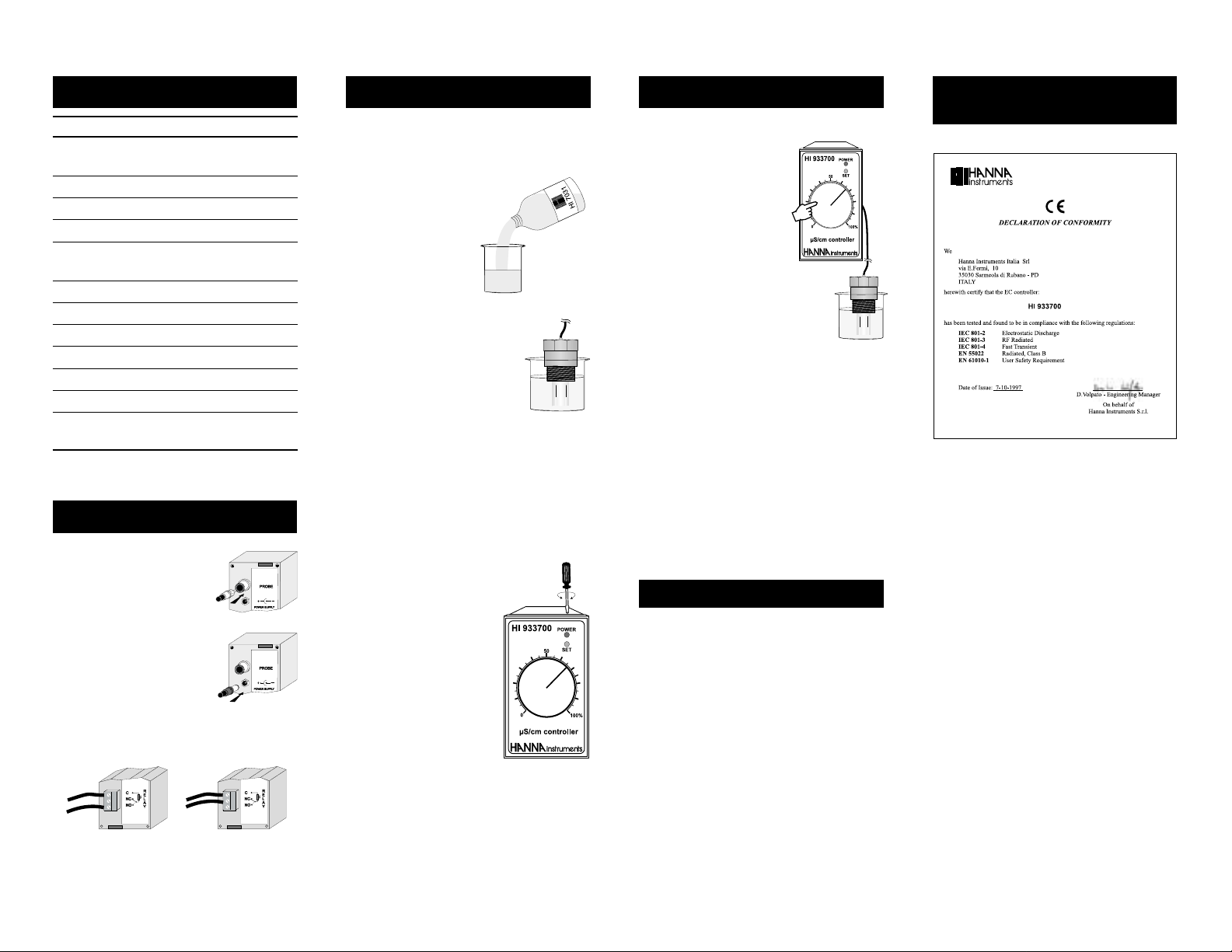
• Connect the EC probe to the RCA
connector marked "PROBE".
• Connect the power adapter cable to
the power socket. The green front
panel LED should light.
• Connect the relay output contacts using the terminal NC
or NO according to your needs.
CALIBRATIONCALIBRATION
CALIBRATION
CALIBRATIONCALIBRATION
For the greatest accuracy, frequent calibration of the instrument is recommended.
• Turn the meter on and connect the probe.
• Pour a small quantity of
HI 7031 EC calibration
solution (for HI 933700/
1 and /2) or HI 7032
calibration solution (for
HI933700/3 and /4) in
a beaker. If possible, use
plastic beakers to minimize
any EMC interference.
• Immerse the EC probe in the solution,
making sure that metal pins are completely submerged.
Note: the probe tip should be completely
submerged in the solution. Moreover, in order not to affect the accuracy of
measurements, it is important that the probe body
does not touch nor stand close to the side walls of the
beaker. The tip can lay on the bottom of the beaker.
• Wait for a couple of minutes for thermal equilibrium.
• Tap the probe gently on the bottom, then shake it while
rotating to make sure no air bubbles have remained
trapped.
• Adjust setpoint at 70%.
• Adjust the calibration trimmer
with a small screwdriver until the
output relay switches.
• Rotate the calibration trimmer in
the opposite direction until the
relay switches again.
• Adjust the calibration trimmer in
the middle of the two relay
switching points.
• The calibration is now complete
and the instrument is ready for use.
The instrument should be recalibrated at least once a month
and after performing probe cleaning procedure.
OPERATIONAL GUIDEOPERATIONAL GUIDE
OPERATIONAL GUIDE
OPERATIONAL GUIDEOPERATIONAL GUIDE
• Select your own set point via the front panel setting
knob.
• Immerse the tip of the EC probe
in the sample.
Note: In order not to affect the
accuracy of measurements, it
is important that the probe
body does not touch nor stand
close to the side walls of the
vessel. The tip may lay on the
bottom of the beaker.
• When the reading of the controller becomes higher or lower than the setpoint
(depending on the model), the red, front panel LED
illuminates and the output relay is activated.
PROBE MAINTENANCE
To minimize clogging and extend the life of the probe, it is
recommended that it be cleaned often or at least once a
month.
• Immerse the tip of the electrode in HI 7061 Cleaning
Solution for one hour.
• If a more thorough cleaning is required, rub the metal
pins with very fine sandpaper.
• After cleaning or when not in use, rinse the probe with tap
water and recalibrate the instrument.
ACCESSORIESACCESSORIES
ACCESSORIES
ACCESSORIESACCESSORIES
HI 7682 EC probe and 1 m (3.3’) cable
HI 70031P 1413 µS/cm (EC) calibration solution, 20 mL
sachet (25 pcs)
HI 70032P 1382 ppm/cm (EC) calibration solution, 20 mL
sachet (25 pcs)
HI 7031L 1413 µS/cm (EC) calibration sol., 460 mL
bottle
HI 7032L 1382 ppm calibration sol., 460 mL bottle
HI 7061L Electrode cleaning solution, 460 mL bottle
HI 710005 12 VDC power adapter, US plug
HI 710006 12 VDC power adapter, European plug
HI 710012 12 VDC power adapter, Australian plug
HI 710013 12 VDC power adapter, Southern Africa plug
HI 710014 12 VDC power adapter, UK plug
CE DECLARATIONCE DECLARATION
CE DECLARATION
CE DECLARATIONCE DECLARATION
OF CONFORMITYOF CONFORMITY
OF CONFORMITY
OF CONFORMITYOF CONFORMITY
Recommendations for Users
Before using these products, make sure that they are entirely suitable for the environment in which they are used.
Operation of these instruments in residential areas could cause unacceptable interferences to radio and TV equipment.
The metal band at the end of the probe is sensitive to electrostatic discharges. Avoid touching
this metal band at all times.
During operation, ESD wrist straps should be worn to avoid possible damage to the probe by
electrostatic discharges.
Any variation introduced by the user to the supplied equipment may degrade the instrument’s
EMC performance.
To avoid electrical shock, do not use these instruments when voltages at the measurement
surface exceed 24 VAC or 60 VDC.
Use plastic beakers to minimize any EMC interferences.
To avoid damages or burns, do not perform any measurement in microwave ovens.
The calibration trimmer is sensitive to electrostatic discharges. It is recommended to use
antistatic screwdriver.
ISTR933700 03/98PRINTED IN PORTUGAL
 Loading...