

Page 1
HI 5315
REFERENCE
Instruction Manual
HI 5315HI 5315
HI 5315
HI 5315HI 5315
Reference Electrode
1
Page 2

HI 5315 Reference ElectrodeHI 5315 Reference Electrode
HI 5315 Reference Electrode
HI 5315 Reference ElectrodeHI 5315 Reference Electrode
I.I.
IntroductionIntroduction
I.
Introduction
I.I.
IntroductionIntroduction
The Hanna HI 5315 reference electrode is a silver-silver
chloride double junction half-cell designed for use with ion
selective electrodes or pH sensors. The electrode utilizes a
quick flush sleeve design. The external reference electrolyte
chamber is refillable. The internal chamber is a permanently filled, gel stabilized, chloride containing electrolyte.
IIII
SpecificationsSpecifications
II.
Specifications
IIII
SpecificationsSpecifications
Type: Ag/AgCl
Operating Temperature: 0-85°C
Operating pH: 0 to 14 pH
Dimensions: 12 mm (OD) x 120 mm
insertion (0.47” x 4.72”)
Connection: Banana Plug
Wetted Materials: PEI
SHE
E°
(calculated): 0.238V
III.III.
Theory of operationTheory of operation
III.
Theory of operation
III.III.
Theory of operationTheory of operation
A reference half-cell provides the electrolytic contact necessary to permit a voltage gradient to be measured across a
measurement membrane, such as an ISE. A Ag/AgCl electrode is the most common type of reference. The Nernst
expression for this type half-cell is expressed in the equation below. Note that the potential is a function of the
chloride concentration.
o
E=E
A chloride electrolyte completes the electrical circuit in the
inner half-cell. A bridge electrolyte is used as a buffer zone
between the inner half-cell and the sample. A small stable
liquid junction voltage is generated where the sample and
electrolyte come into contact. The size of this voltage, the
identity of the diffusing ions and how this barrier is formed
dictate stability. The barrier zone for this reference is a
narrow ring shaped opening formed between the outer
sleeve and the lower edge of the skirt shaped inner body.
- 0.059 log [Cl
AgCl
--
-
-]
2
Page 3
IVIV
..
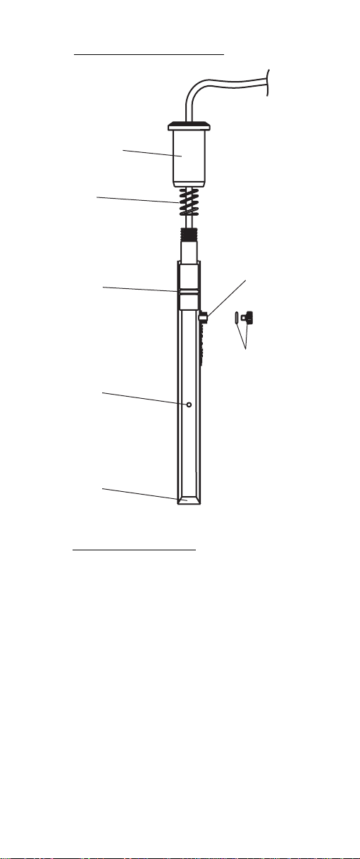
HI 5315 design elementsHI 5315 design elements
IV
.
HI 5315 design elements
IVIV
..
HI 5315 design elementsHI 5315 design elements
Upper Cap
Spring
O-Ring
Ceramic Junction
on Inner Stem
Liquid junction
V. V.
Reference Fill SolutionsReference Fill Solutions
V.
Reference Fill Solutions
V. V.
Reference Fill SolutionsReference Fill Solutions
Fill Hole
O-Ring and
Plug
The fill solution used in the external electrolyte chamber of
this electrode is replaceable. Table 1 lists Hanna‘s ion
selective electrode (ISE) offering along with the recommeded
fill solutions used when making an ion measurement. A
bottle of this solution is provided with the ISE when shipped.
The fill solutions listed will not interfere with the sensing
electrode or react with the sample. They are formulated to
minimize liquid junction potentials and to produce the
most stable and reproducible electrode potential.
ThThw b
Verify you are using the correct fill solution with your
electrode.
ab
3
Page 4

d reproducible potential.
1ELBAT1ELBAT
1ELBAT1ELBAT
Recommended Fill Solutions for ISERecommended Fill Solutions for ISE
1ELBAT
Recommended Fill Solutions for ISE
Recommended Fill Solutions for ISERecommended Fill Solutions for ISE
edoCnoitpircseDnoituloSlliF
2004IHllec-flahedimorBIH2707
3004IHllec-flahmuimdaCIH2707
4004IHllec-flahmuiclaCIH2807
7004IHllec-flahedirolhCIH2707
8004IHllec-flahcirpuCIH2707
9004IHllec-flahedinayCIH2707
0104IHllec-flahediroulFIH5707
1104IHllec-flahedidoIIH2707
2104IHllec-flahetafluS/daeLIH2707
3104IHllec-flahetartiNIH8707
4104IHllec-flahmuissatoPIH6707
5104IHllec-flahedifluS/revliSIH2707
VI.VI.
Electrode Preparation:Electrode Preparation:
VI.
Electrode Preparation:
VI.VI.
Electrode Preparation:Electrode Preparation:
1. Remove the Parafilm® seal wrapped over the ceramic
junction on inner stem and discard. This is only used
for shipping and long term storage.
2. Rinse inner body with deionized water making certain
to wet o-ring found on the inner stem.
Remove
Water
Deionized
4
Parafilm
Page 5

3.
Reassemble electrode by gently pushing the inner
assembly into the outer body (from the bottom).
Slide the spring and upper cap down the cable and
over the top of the inner stem. Screw the upper cap
into place.
4. Unscrew and remove the fill hole plug and o-ring on
fill hole spout.
5.
Select the appropriate fill solution from Table 1. Use
the dropper pipette provided to add a few drops of fill
solution to the electrode. Invert electrode to wet the oring and rinse the electrolyte chamber.
6. Holding the body of the electrode gently press the
upper cap with your thumb. This permits the fill
solution to drain out of the body. Release your thumb
and verify electrode returns to its original position.
(You may need to gently assist for this to occur).
E
C
N
E
5
R
1
E
3
F
5
E
I
R
H
7. Tighten the upper electrode cap onto the body and fill
electrode body until the fill solution volume is just
below the fill hole.
8. Position the reference electrode with appropriate ion
selective electrode (ISE) in a Hanna HI 76404 electrode
holder (or equivalent) and connect banana plug to
the reference jack of the ISE meter.
5
Page 6

VII.VII.
General GuidelinesGeneral Guidelines
VII.
General Guidelines
VII.VII.
General GuidelinesGeneral Guidelines
• During measurement always operate electrode with
the fill hole open.
• Verify protective cap has been removed.
• During normal use, fill solution will slowly drain out
of the tapered cone junction at the bottom of the
electrode. Excessive loss (>4 cm drop within 24 hours)
is not normal. If this occurs verify the upper cap is
tightened and the interface between the internal cone
and outer body is free of debris.
• Add fill solution daily to maintain a good head
pressure. For optimum reference response, this level
should be maintained and not be allowed to drop
more than 2-3 cm (1-inch) below fill hole.
• When changing from one fill solution to another, drain
1st fill solution, rinse with an aliquot of the new
solution, drain, then refill with new fill solution.
• Components found in the fill solutions should not
interfere with the ion being measured. Verify the correct
solution is being used.
• Do not use an electrode if crystallized salts are visible
inside the electrode. Drain electrode, disassemble and
rinse internal body with deionized water. Reassemble
and refill with fresh fill solution.
• If an erratic measurement occurs, check to see if foreign
matter is seen trapped near the internal cone. Drain
and refill with fresh fill solution.
• The internal chamber of this electrode is gel filled. If
the electrode has been left dry for long periods of time
the gel may be dehydrated giving unstable readings.
Disassemble electrode and soak internal assembly in
HI 7075 fill solution. Verify the ceramic junction is
wetted by the fill solution. Warming the solution
slightly (50°C) before soaking it will hasten this
process. Permit the electrode to cool completely while
immersed in this solution.
6
Page 7

VIII.VIII.
Disassembly - AssemblyDisassembly - Assembly
VIII.
Disassembly - Assembly
VIII.VIII.
Disassembly - AssemblyDisassembly - Assembly
Disassembly is normally not required or recommended. If
crystals or other matter are seen between outer body and
inner cone, the electrode may be disassembled for cleaning
or inspection. Protect the cone surface from oils or dirt by
using gloves or lab tissues.
1. Drain fill solution from electrode body by depressing
the upper cap while holding the outer body.
2. Rinse inner body with deionized water and drain by
pressing the upper cap.
3. Unscrew upper cap and slide cap and spring up the
sensor cable toward the connector.
4. Push the inner body through the outer sleeve by gently
pushing down on the inner body near the threads.
5. Grasp the cone and gently pull assembly out of sleeve.
6. Cone may be cleaned with deionized water and a soft
lab tissue (HI 731318).
7. Clean and inspect internal surface of outer body.
8. Reassemble electrode by gently pushing the inner
stem assembly into the outer body, sliding spring
down cable, and screwing cap into place. (Refer to
Section VI; Electrode Preparation).
9. Refill electrolyte, flush junction, and then top off
electrolyte.
IXIX
StorageStorage
IX.
Storage
IXIX
StorageStorage
The HI 5315 reference electrode may be stored in air or
aqueous solutions between sample measurements.
If the electrode will be used frequently and needs to be
ready for use, take measures to prevent evaporation of fill
solution. Top off fill solution, replace o-ring and fill hole
plug on the fill hole opening, and place protective cap over
junction tip. Store electrode upright. Before using, flush
junction once and top off fill solution.
For long term storage, disassemble electrode and wash all
salts from assembly with deionized water. Wrap ceramic
junction on inner stem with Parafilm® or other sealing
film. Store dry and disassembled.
7
Page 8

MAN5315 07/06REV4
WARRANTY WARRANTY
WARRANTY
WARRANTY WARRANTY
Hanna Instruments ISE series electrodes are warranted to be free of
defects in material and workmanship for 6 months from date of purchase
when used for their intended purpose and maintained according to
instructions. If they fail to work when first used contact your dealer
immediately. Damage due to accidents, misuse, misapplication,
tampering or lack of prescribed maintenance is not covered.
Hanna Instruments reserves the right to modify the design, construction
or appearance of its products without advance notice.
8
 Loading...