

Page 1
Instruction Manual
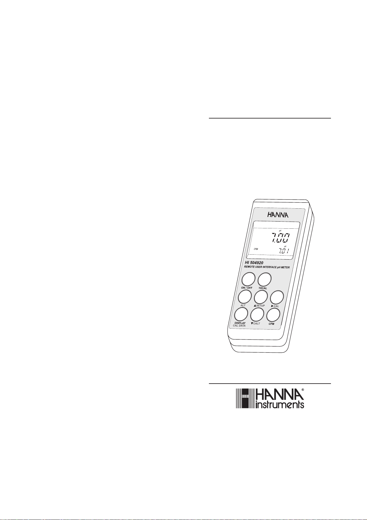
HI 504920
Remote User Interface
pH Meter
www.hannainst.com
Page 2
Dear Customer,
Thank you for choosing a Hanna Instruments Product.
Please read this instruction manual carefully before using the instrument. This manual will provide you with all the necessary information
for correct use of the instrument.
If you need additional technical information, do not hesitate to e-mail
us at tech@hannainst.com.
This instrument is in compliance with directives.
WARRANTY
All Hanna Instruments meters are warranted for two years against defects in
workmanship and materials when used for their intended purpose and maintained
according to instructions. Probes are warranted for a period of six months. This
warranty is limited to repair or replacement free of charge.
Damages due to accident, misuse, tampering or lack of prescribed maintenance are
not covered. If service is required, contact the dealer from whom you purchased the
instrument. If under warranty, report the model number, date of purchase, serial number and the nature of the failure. If the repair is not covered by the warranty, you will be
notified of the charges incurred. If the instrument is to be returned to Hanna Instruments, first obtain a Returned Goods Authorization number from the Customer Service
department and then send it with shipping costs prepaid. When shipping any instrument, make sure it is properly packaged for complete protection.
PRELIMINARY EXAMINATION
Remove the instrument from the packing material and examine it
carefully to make sure that no damage has occurred during shipping.
If there is any damage, notify your Dealer.
Each meter is supplied complete with:
• HI 62920 amplified pH electrode with built-in temperature
sensor, DIN connector and 2 m cable
• Hanna HI 504910 interface cable (HI 7920)
• pH 4.01 buffer solution, 20 mL sachet
• pH 7.01 buffer solution, 20 mL sachet
• Instruction manual
• 1.5V AA size alkaline batteries (4 pcs)
• 12 Vdc power adapter
• Rugged carrying case.
Note: Save all packing material until you are sure that the
instrument functions correctly. All defective items must be
returned in their original packaging together with the supplied accessories.
TABLE OF CONTENTS
PRELIMINARY EXAMINATION ..................................................................... 3
GENERAL DESCRIPTION ........................................................................... 3
FUNCTIONAL DESCRIPTION .......................................................................5
SPECIFICATIONS .................................................................................. 6
INITIAL PREPARATION .............................................................................. 7
CALIBRATION ..................................................................................8
pH CALIBRATION PROCEDURE ........................................ 8
mV CALIBRATION PROCEDURE .................................... 1 0
TEMPERATURE CALIBRATION PROCEDURE .................... 10
USE AS REFERENCE pH METER .............................................................. 11
SETUP MODE ............................................................................... 14
TAKING MEASUREMENTS ...................................................................... 17
GOOD LABORATORY PRACTICE (GLP) ..................................................... 19
BATTERY REPLACEMENT ....................................................................... 21
TEMPERATURE-RESISTANCE CORRELATION
FOR HANNA PH SENSITIVE GLASS .......................................................... 2 2
ELECTRODE CONDITIONING AND MAINTENANCE ...................................... 23
ACCESSORIES ...................................................................................... 2 5
CE DECLARATION OF CONFORMITY ........................................................ 27
GENERAL DESCRIPTION
HI 504920 is a complete portable pH/ORP/temperature meter, to be
used mainly with Hanna HI 504910 Digital Transmitter for two
different applications: it can be a reference pH meter for calibrating
the HI 504910 Digital Transmitter, or it can be set as user interface
for the HI 504910 as well.
All pH measurements are automatically compensated for temperature
(ATC). The instrument housing is made of rugged, lightweight material,
making it truly portable.
Five memorized buffers (4.01, 6.86, 7.01, 9.18 and 10.01 pH) and
wrong buffer recognition technology make calibration simple and error
free. One or two-point calibration can be performed.
An user friendly interface provides clear messages regarding errors,
functions and more.
An alarm time-out is available to alert the user if too much time has
elapsed since the last pH calibration and that re-calibration may be
required.
The meter provides a controlled access to calibration and GLP settings
32
Page 3
through a password protection method.
The Battery Error Preventing System (BEPS) detects when the batter-
ies level becomes weak.
When the batteries are getting low, a clear indication is displayed on
LCD to warn the user of this condition. However, the meter continues
to measure correctly even when the low battery indication is displayed. The meter automatically switches itself off when the batteries
are too weak to support proper function.
For long term field and lab applications, this meter can be connected to
a 12 VDC adapter.
The meter allows the user to enter an ID code to uniquely identify the
instrument.
Made of lightweight ABS material, the water-resistant rugged casing
is built to last.
The meter is in compliance with IP67 standards: dust-tight, protected
against the effects of temporary immersion in water and designed to
provide laboratory results and accuracy under harsh industrial conditions.
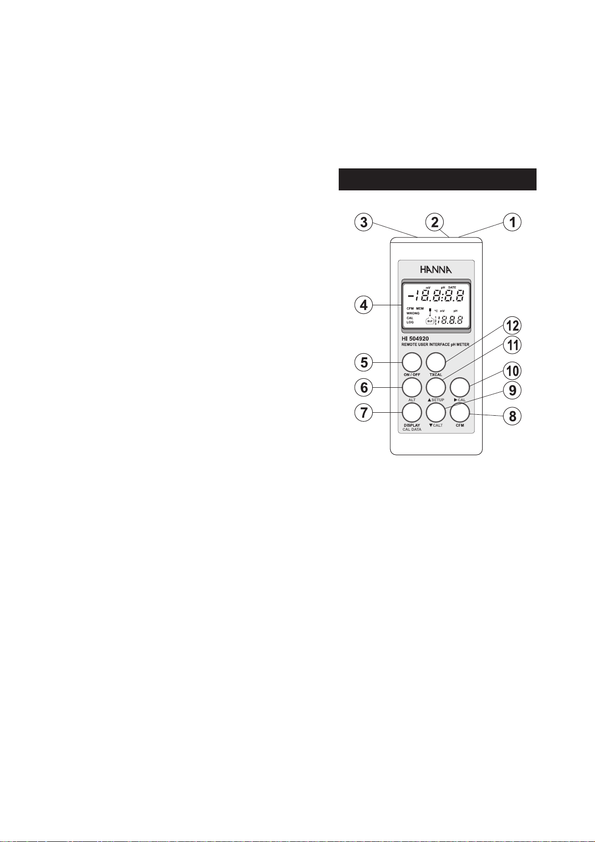
FUNCTIONAL DESCRIPTION
1) Power adapter plug
2) Connector for the HI 504910 interface cable (HI 7920)
3) Electrode Connector
4) Liquid Crystal Display (LCD)
5) ON/OFF key, to turn the meter on and off
6) ALT key, to alternate key function
7) DISPLAY / CAL DATA key, to select measurement ranges, to
display time and date, and to view calibration data (with ALT)
8) CFM key, to confirm values
9) CALT key, to move down or calibrate temperature (with ALT)
10) CAL key, to move right or calibrate pH (with ALT)
11) SETUP key, to move up or enter setup mode (with ALT)
12) TXCAL key, to calibrate the HI 504910 Digital Transmitter
54
Page 4
SPECIFICATIONS
INITIAL PREPARATION
Range pH -4.00 to 19.99 pH
mV ±600.0 mV ; ±2000 mV autoranging
Temp. -20 to 120 °C
Resolution pH 0.01 pH
mV 0.1 mV between ±400 mV
0.2 mV from +400 to +600 mV
0.2 mV from -400 to -600 mV
1 mV outside
Temp. 0.1 °C from -10 to 120 °C / 1°C below -10°C
Accuracy pH ±0.01 pH
(@20°C/68°F) mV ±0.2 mV between ±400 mV
±0.4 mV from +400 to +600 mV
±0.4 mV from -400 to -600 mV
±2 mV outside
Temp. ±0.4 °C from 0 to 70°C / ±1°C outside
Typical EMC pH ±0.02 pH
Deviation mV ±1 mV between ±600 mV
±2 mV outside
Temp. ±0.4°C
pH Calibration Automatic 1 or 2 points with 5 memorized
buffers (4.01, 6.86, 7.01, 9.18 and 10.01 pH)
mV Calibration Automatic 2 points at 0, 350 mV or 3 points
at 0, 350 and 1900 mV
Temperature Automatic from -20 to 120°C
Compensation
pH Electrode HI 62920 Amplified, with built-in temperature
sensor, matching pin, DIN connector and Titanium body (included)
ORP Electrode Amplified ORP electrode with DIN connector
(see accessories)
Input Impedance 10
12
Ohm
Infrared optical through HI 7920 interface cable
interface towards
HI 504910
Power supply 4x1.5V AA (IEC LR6) batteries/300 hours typical life
or 12 VDC adapter
Casing IP 67
Environment 0 to 50°C / 100% RH
Dimensions 196 x 80 x 60 mm (7.7 x 3.1 x 2.4")
Weight 500 g (18 oz)
Each meter is supplied complete with batteries and 12 VDC adapter.
To power the instrument with batteries, remove the back cover,
unwrap the batteries and install them while paying attention to the
polarity.
If using external power supply, connect the 12 VDC adapter to the
power adapter plug.
To prepare the instrument for use, connect the pH or ORP electrode to
the connector located on the top of the instrument.
To switch the meter on, press the ON/OFF key.
The batteries charge status or "LINE" message
(if external power adapter is connected) will be
displayed on the LCD for a few seconds.
The meter is now ready to operate.
To maximize battery life, the meter is automatically switched off after 5
minutes of non-use (this feature can be disabled through setup code
20). To reactivate the instrument press the ON/OFF key.
Before proceeding with pH measurements follow the calibration proce-
dure.
Note: When the use of an alternate function (SETUP, CAL, CAL DATA
and CALT) is requested, press and hold the ALT key first and
then the second desired key.
Note: To prevent damage to the electrode, remove it from the sample
before turning the meter off.
When the meter is OFF, detach the electrode from the meter
before immersing it in the storage solution.
76
Page 5
CALIBRATION
pH CALIBRATION
For greatest accuracy, it is recommended to frequently calibrate the
instrument. For a faster procedure, it is possible to calibrate at 1
point, but it is always a good practice to calibrate at 2 points.
For a two-point calibration two of the following pH buffers can be
used: pH 4.01, pH 7.01 (or 6.86), pH 10.01 (or 9.18).
In the case of a two-point calibration in the acidic range (from 0 to
7 pH), use pH 7.01 (or 6.86) buffer as first solution and pH 4.01
buffer as second solution. If testing in the alkaline range (from 7 to
14 pH), use pH 10.01 (or 9.18) buffer as second solution.
Due to electrode conditioning time, the electrode must be kept
immersed a few seconds to stabilize. The meter is equipped with a
stability indicator and the user will be guided step by step with easy
indications on the LCD during the calibration. This will make the
calibration a simple and error-free procedure.
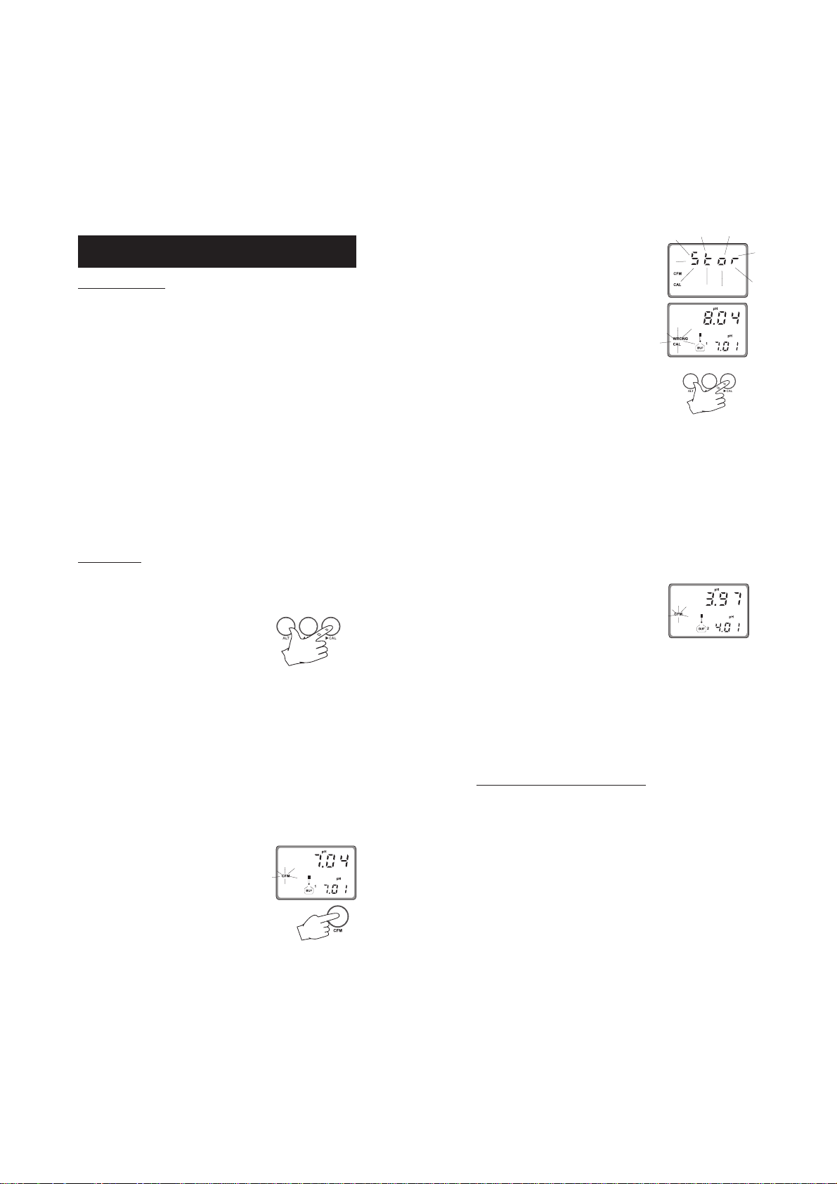
PROCEDURE
1. Rinse the electrode with a portion of the first calibration buffer or
clean water. Dip the tip (4 cm/1½") of the electrode into a
beaker containing the solution.
2. Press (ALT+) CAL when the meter dis-
plays pH measurement.
3. Enter the password (if different from "0000") with the arrow keys.
4. Press CFM to confirm the password or (ALT+) CAL to exit.
5. If password is correct, the meter displays "7.01pH" on the
secondary LCD with the "BUF 1" and "CAL" indications. The
primary LCD shows the uncalibrated pH reading.
Note: The pH buffer value (displayed on the secondary LCD) varies
with temperature. For example, at 20°C it shows 4.00 -7.03 -
10.06, at 25°C it shows 4.01-7.01-10.01.
6. Select the first buffer solution value with or if necessary.
7. When the "CFM" symbol blinks, the read-
ing is stable and calibration can be
confirmed.
8. Press CFM to confirm the first buffer.
9. If everything is satisfactory the LCD will
display "Stor" and then the expected
value for the second buffer (two-point
calibration). If a wrong solution or electrode has been used or if the buffer is
polluted, "WRONG" will be displayed to
alert the user.
10. If a single point calibration is required,
press (ALT+) CAL to exit the calibration
mode and maintain the previous slope
calibration. The instrument then checks
the electrode parameters and advises user
of possible abnormalities by "old probe"
and "dead probe" indications.
11. Press or to select the second buffer value. The meter will
display the "BUF 2" indication.
12. Rinse the electrode with some of the second buffer solution or clean
water.
13.Dip the tip (4 cm/1½") of the pH electrode into a beaker
containing the second buffer.
14. When the "CFM" symbol blinks, press CFM
to confirm the second calibration point.
15. The LCD will display "Stor". The instrument checks the electrode
parameters and advises the user of possible abnormalities by "old
probe" and "dead probe" indications (in these cases, repeat the
calibration procedure with fresh buffers). If everything is satisfactory
the meter is calibrated and it returns to normal operational mode.
Note: To abort the calibration procedure and leave the calibration data
unchanged, press ALT and CAL before confirming the first point.
CALIBRATION ERROR MESSAGES
If the "old probe" or "dead probe" messages are displayed, or if the
WRONG tag blinks during calibration, check the electrode by following
the conditioning and maintenance procedures and repeat calibration.
If calibration can not be successfully performed, the pH electrode
might have to be replaced.
Note: See "GLP" section for more details about "old probe" and "dead
probe" messages.
98
Page 6

mV CALIBRATION
Contact your nearest Hanna Service Center for periodic mV calibration.
It is recommended to have the meter recalibrated for mV reading at
least every two years.
TEMPERATURE CALIBRATION
(for technical personnel only)
Contact your nearest Hanna Service Center for periodic temperature
calibration.
It is recommended to have the meter recalibrated for temperature
reading at least every two years.
Temperature calibration at your site should be performed only by
skilled technical personnel as described in the following procedure
(two-point calibration at 0.0 and 50.0°C):
1. Immerse the pH electrode with the built-in temperature sensor in
a 0°C ice bath.
2. Press (ALT+) CALT to enter temperature calibration mode.
3. Enter the password.
4. The meter will display "0.0°C" on the secondary LCD with the
"BUF 1" and "CAL" indications.
5. When the reading is stable the "CFM" tag starts blinking.
6. Press CFM to confirm. The secondary LCD will then display
"50.0°C" with the "BUF 2" indication.
7. Immerse the pH electrode with the built-in temperature sensor in
a 50°C bath.
8. When the reading is stable the "CFM" tag starts blinking.
9. Press CFM to confirm, save the new calibration data and return to
normal mode.
Note: To abort the calibration procedure and leave the calibration data
unchanged, press (ALT+) CALT at any time before the last step.
USE AS REFERENCE pH METER
HI 504910 QUICK pH CALIBRATION
HI 504910 can be calibrated frequently through HI 504920 without
interrupting the normal measurement.
This is accomplished through a single point pH calibration at the pH
value of the solution monitored by HI 504910.
Perform the following steps:
1. Connect the supplied infrared optical interface cable (HI 7290) to
the calibrator and to the HI 504910 Digital Transmitter.
2. Immerse the pH electrode into the solution which HI 504910 is
measuring, as close as possible to the HI 504910 pH probe. Wait
a few seconds for the electrode to stabilize.
3. When the meter displays pH measurement, press TXCAL on the HI 504920
calibrator.
4. The LCD will display "CALt" for a couple of
seconds to indicate that the calibration
of the HI 504910 transmitter is in
progress.
5. If the calibration is completed correctly,
the LCD will flash the "Good" message for
a couple of seconds.
6. The primary LCD then shows the pH
reading of the HI 504910 transmitter,
while the secondary one displays the pH
reading of the reference meter. Both pH tags blink alternatively.
Note: The two values may differ a little if the solution under
measurement is not stable. For an accurate calibration, it is
recommended to perform the above procedure only when
readings are stable.
7. To exit the calibration mode and return
to normal measurement, press TXCAL.
1110
Page 7

Note: At point 5, if the probe offset is
outside the allowed limits, if HI
504910 is configured to measure ORP,
or if some other error occurs, the LCD
shows a blinking "bAd" message. To cancel this message and
return to normal mode, press TXCAL. Then restart the calibration procedure from the beginning.
Note: Although it is recommended to perform the entire calibration
procedure with the infrared optical interface cable connected
between HI 504920 and HI 504910 (step 1), it can happen
that the HI 504910 must be located in a place difficult to
reach when the HI 504920 pH probe is immersed in the
solution.
In this case, step 1 can be skipped. After step 4 the primary
LCD will show the blinking "CALt" message and the secondary
one a countdown starting from 120 seconds.
In this situation, the pH probe can be taken out of the
solution and the interface cable must be connected to the HI
504910 before the countdown reaches zero.
Calibration will then continue from step 5. At step 6 the pH
tag of the secondary LCD does not blink, because the corresponding pH reading is the one taken with the HI 504920 pH
probe immersed when TXCAL was pressed.
If the interface cable is not connected before the end of the
countdown, the LCD shows
the "tiMEout" message and
the calibration procedure is
aborted.
HI 504910 pH READING CHECK
The check of the HI 504910 pH reading against the HI 504920 pH
reading is possible at any time.
Perform the following steps:
• Connect the infrared optical interface cable to HI 504910.
• Press (ALT+) TXCAL.
• The primary LCD shows the HI 504910
pH reading and the secondary one displays the HI 504920 pH reading. Both
pH tags blink alternatively.
• Press (ALT+) TXCAL to return to normal mode.
Note: In case of a communication error
between HI 504920 and HI 504910,
the LCD shows the "rSEr" message.
Check interface cable and connections.
Note: If the LCD shows "...", verify that HI 504910 is configured to
measure pH and not ORP.
Note: To perform a two-point calibration procedure with standard pH
buffers (pH 4.01, 6.86, 7.01, 9.18, 10.01) through the HI
504910 terminal mode, see the "Setup mode section", code
90.
Note: A probe life verification (as described in the "GLP" section) is
performed on the HI 504910 pH probe; the message "old
probe" or "dead probe" could appear at the end of calibration.
1312
Page 8

SETUP MODE
Setup can be used to view data regarding instrument status (e.g.
battery charge) or to change the meter parameters (e.g. time).
• To enter this mode press (ALT+) SETUP
while the meter is in measurement mode.
• The setup code "00" will blink on the
secondary LCD and "SEt" will be displayed on the primary one.
• Select the code of the desired
parameter using the or
key.
PARAMETER SETTINGS
• Once the parameter code (and password if
needed) has been entered, the current
value of the selected parameter will be
displayed on the primary LCD and the
parameter code on the secondary one. The parameter or a part of it
will blink (e.g. only the hour blinks if time has been selected).
• Enter the new value using the arrow keys.
• If there is another part of the parameter to be set (e.g. minutes
for the time), press DISPLAY to gain access and then enter the
new value using the arrow keys.
• Press CFM to confirm the code.
Note: If (ALT+) SETUP are pressed before code confirmation, the
meter returns to measurement mode.
• If the selected parameter is password protected, the lower LCD will
display "PAS" and the password must be entered to proceed.
Otherwise, the current parameter value will be displayed.
PASSWORD PROTECTION
Setting of time, date and calibration alarm time-out are password
protected and the user will be asked to enter the password to change
these parameters. After code confirmation the upper LCD will display
"0000".
• If password is set to 0000 (factory setting), just press CFM to
confirm.
• If password is set to a value different from 0000, enter the
password with the up and down arrow keys and then press CFM
to confirm.
• If the password is not correct, the meter displays the "WRONG"
indication and asks for the password again.
• If the password is correct, the meter provides access to the
parameter.
• Press CFM to confirm the value.
• If the entered value is not acceptable, the "WRONG" indication
will be displayed for a few seconds and then the meter will ask for
a correct value.
• If the confirmed value is accepted, the meter will pass to the next
parameter (asking for the password if it is protected).
Note: If (ALT+) SETUP are pressed before parameter value confir-
mation, the meter will not update the parameter and after
escaping will ask for a new setup code.
The following table lists the setup codes along with the description of the
specific setup items, their valid values and the factory settings (default):
Code Valid values Default
00 Instrument ID code 0000 to 9999 0000
01 Current time
02 Current date
03 Current year
1
1
1
hh:mm 00:00
dd.mm 01.01
YYYY 1998
10 Calibration alarm time-out 01 to 99 days , OFF OFF
20 Auto-Off/Power down time-out ON, OFF ON
21 Firmware version
22 Battery level test
90 HI 504910 terminal mode
99 Password
2
0000 to 9999 0000
1514
Page 9

1
The meter automatically checks for entered time/date accuracy as follows:
0≤hh≤23; 0≤mm≤59; 01≤dd≤28/29/30/31; 1≤MM≤12; 1998≤YYYY≤2097.
2
To change the password, the correct code must be entered first. If the password
has been forgotten, the password protected features are no longer accessible;
in this case contact your nearest Hanna Service Center.
Some of the setup parameters are explained below.
Code 00 - Setting the identification (ID) code
When using several identical meters it may be useful to uniquely
identify them by assigning an ID code to each meter.
• Select code 00.
• Enter a 4-digit value using the arrow keys.
• Press CFM to confirm the value.
Code 20 - Auto-off
The auto-off time-out is factory set at 5 minutes.
• Select code 20 to disable/enable this feature.
Code 22 - Battery level test
• Select code 22.
• If the meter is connected to an external power adapter, the LCD
displays "LINE" otherwise it shows "bAtt" on the primary display, and
the remaining battery charge percentage on
the secondary one (100 means fully charged
battery and 0 indicates the minimum voltage that allows the meter to operate).
Note: The battery level test is also performed any time the meter is
turned on.
Code 90 - HI 504910 terminal
• Select code 90.
• Press CFM to confirm the value.
• HI 504920 enters a "terminal mode" during which it works as
keyboard and LCD for HI 504910, allowing complete calibration,
configuration and error check of HI 504910 (see the HI 504910
instruction manual for details).
Note: The "LOG" tag blinks while in HI 504910 terminal mode.
• Press (ALT+) TXCAL to exit this mode and skip into measurement
mode. Put HI 504910 in normal measurement mode before
exiting.
Note: The LCD shows the "rSEr" message when a connection between
HI 504920 and HI 504910 can not be established. In this
case, check interface cable and connections.
TAKING MEASUREMENTS
pH MEASUREMENTS
Connect the pH electrode with the built-in
temperature sensor to the meter and press
ON/OFF to power on the instrument.
If the electrode is not connected the LCD will display the "no probe"
message and then dashes.
For greatest accuracy, it is recommended to set
the Calibration alarm time-out to the value
appropriate to your specific use and calibrate
the meter as soon as the "DATE" warning
symbol blinks on LCD (see GLP section).
To take pH measurements, remove the electrode protective cap and simply submerge
the tip (4 cm/1½") of the electrode in the
solution to be tested and stir gently. Allow
for the reading to stabilize.
The temperature is displayed on the secondary LCD.
The pH reading is automatically temperature compensated (ATC).
If the reading is out of range, the meter displays "----". A blinking
reading means that the electrode is "dead".
By continuously pressing the DISPLAY key
the following information will be displayed
on the primary LCD:
• mV reading (the mV scale is auto-ranging:
when the reading is outside ±600 mV,
the decimal point automatically disappears).
• Time
• Day / Month
• Year
Pressing DISPLAY again, the meter returns to pH reading.
Note: When date or time is displayed, it is possible to change them
directly by pressing (ALT+) SETUP.
Note: If measurements are taken successively in different samples, it
is recommended to rinse the electrode thoroughly with deionized water or, if not available, tap water first and then with
some of the next sample to condition the electrode before
immersing it in the sample.
1716
Page 10

ORP MEASUREMENTS
Connect the ORP electrode to the meter and press the ON/OFF key.
The meter automatically sets the mV range.
If the electrode is not connected the LCD will display the "no probe"
message and then dashes.
To take ORP measurements, remove the electrode protective cap and
simply submerge the tip (4 cm/1½") of the electrode in the solution
to be tested, stir gently and allow for the reading to stabilize.
Note: The ORP electrodes are not provided with the temperature
sensor.
By continuously pressing the DISPLAY key the following information
will be displayed on the primary LCD:
• Time
• Day / Month
• Year
Pressing DISPLAY again, the meter returns to mV reading.
Note: If measurements are taken successively in different samples, it
is recommended to rinse the electrode thoroughly with deionized water or, if not available, tap water first and then with
some of the next sample to condition the electrode before
immersing it in the sample to be tested.
TEMPERATURE MEASUREMENTS
The temperature sensor is integrated in the pH electrode.
Immerse the pH electrode in the solution, wait a few minutes for the
temperature to stabilize and press the ON/OFF key. The temperature
will be displayed on the secondary LCD.
Note: If temperature measurement is out of range the LCD will
display "- - -".
GOOD LABORATORY PRACTICE (GLP)
GLP is a set of functions that allows the storage or retrieval (when
necessary) of data regarding the maintenance and status of the
electrode. The meter can automatically analyze the data and advise
the user with a clear message if a problem is found.
PROBE LIFE VERIFICATION
At the end of calibration, the meter checks if the electrode offset is within
±30 mV range and the slope between 53.5 and 62 mV/pH. If the
values are not within these limits, the message "old probe" scrolls across
the LCD. The electrode is still working, but it is necessary to perform a
cleaning procedure (see "Electrode cleaning and maintenance" section)
or replace it.
If the offset is outside the ±60 mV range or the slope is outside the
40 to 70 mV/pH interval, the "dead probe" message will scroll across
the LCD; the reading will blink on the primary LCD to warn the user
that it is not reliable.
ELECTRODE IDENTIFICATION
At start-up the meter checks if the electrode is connected. If not, the
message "no probe" scrolls across the LCD and dashes ("----") are
displayed in place of the reading.
If the meter detects a "dead probe" situation, the reading will blink.
CALIBRATION ALARM TIME-OUT
The calibration alarm time-out is available only for pH calibration.
It is possible to set (through setup code 10) the number of days
before the next required calibration procedure. User can set a value
from 01 to 99 days. The default value is 07. Set the parameter to
"OFF" to disable this feature.
When turned on, the meter checks if the timeout time has expired. If yes, the message "Cal
date" scrolls across the LCD and the "DATE"
tag blinks as a reminder.
LAST CALIBRATION DATA
Last calibration data are automatically stored after a successful
calibration and they can be displayed by pressing the CAL DATA key.
To view the pH calibration data
• Press (ALT+) CAL DATA when the meter displays pH reading.
1918
Page 11

+
-
• The LCD will then display the last pH calibration date.
• Press DISPLAY to scan remaining data, in the following order:
last calibration time;
electrode offset value in mV ("OFF" appears on the secondary LCD);
electrode slope in mV/pH ("SLP" appears on the secondary LCD);
first calibration point buffer;
second calibration point buffer (only if a 2-point calibration has
been performed).
If calibration was performed with an old or dead probe, the
message "old probe" or "dead probe" will scroll on LCD.
• The meter then returns to normal mode. Press (ALT+) CAL DATA
to escape before viewing all the data.
To view the mV calibration data
• Press (ALT+) CAL DATA when the meter displays mV reading.
• The LCD will then display the last mV calibration date.
• Press DISPLAY to scan remaining data, in the following order:
last calibration time;
first calibration point;
second calibration point;
third calibration point (only if a 3-point calibration has been
performed).
• The meter then returns to normal mode. Press (ALT+) CAL DATA
to escape before viewing all the data.
BATTERY REPLACEMENT
When the batteries are inserted and no power adapter is connected,
the meter can recognize two different batteries charge levels.
1. Weak batteries - "bAt" indication
is displayed on the secondary LCD
alternating the temperature reading. The meter can still work for
about 10 hours.
2. Dead batteries - meter shuts off
and stops working to avoid erroneous readings.
Battery replacement must only take place
in a non hazardous area using 1.5V
alkaline AA type batteries.
In order to replace rundown batteries,
simply remove the two screws of the rear
cover and replace the four 1.5V AA
batteries with new ones, while paying
attention to the correct polarity.
A 12 VDC power adapter can also be used to power the unit (see
accessories).
Note: The instrument uses the following configuration.
It is recommended to purchase the Hanna voltage adapters that use
the proper polarity configuration.
However, HI 504920 can be used also with other adapters. In this
case, check the correct polarity of the adapter before connecting it to
the meter.
2120
Page 12

TEMPERATURE-RESISTANCE CORRELATION FOR
0
0+10+20+30+40+50+60+70+80+90
C
HANNA pH SENSITIVE GLASS
ELECTRODE CONDITIONING
AND MAINTENANCE
The resistance of glass electrodes partially depends on the temperature.
The lower the temperature, the higher the resistance. It takes longer time
for the reading to stabilize if the resistance is higher. In addition, the
response time will suffer to a greater degree at temperatures below 10°C.
Ω
Ω
9
2x10
-10
9
1x10
-10
8
-10
2x10
8
1x10
-10
7
2x10
-10
-10
7
1x10
-10
-20-2
-2 0 -1 0 0 +10 +20+30+40 +50 +60 + 70 +80 +90 °C
°
Since the resistance of the pH electrode is in the range of 200 Mohm,
the current across the membrane is in the pico-Ampere range. Large
currents can disturb the calibration of the electrode for many hours.
For these reasons high humidity environments, short circuits and
static discharges are detrimental to a stable pH reading.
The pH electrode's life also depends on the temperature. If constantly
used at high temperatures, the electrode life is drastically reduced.
Typical Electrode Life
Ambient Temperature 1- 3 years
90 °C Less than 4 months
120°C Less than 1 month
High concentrations of sodium ions interfere with readings in alkaline
solutions; the pH at which the interference starts to be significant
depends upon the composition of the glass. This interference is the
alkaline error and causes the pH to be underestimated. Hanna's
glass formulations have the indicated characteristics.
Alkaline Error
Sodium Ion Correction for the Glass at 20-25°C
Concentration pH Error
0.1 Mol L-1 Na
1.0 Mol L-1 Na
+
+
13.00
13.50
14.00
12.50
13.00
13.50
14.00
0.10
0.14
0.20
0.10
0.18
0.29
0.40
Note: To prevent damage to the electrode, remove the pH electrode
from the sample before turning the meter off.
If the meter is OFF, detach the electrode from the meter before
immersing the electrode in the storage solution.
PREPARATION
Remove the protective cap.
DO NOT BE ALARMED IF SALT DEPOSITS ARE PRESENT.
This is normal with electrodes and they will disappear when rinsed
with water.
During transport tiny bubbles of air may form inside the glass bulb.
The electrode cannot function properly under these conditions. These
bubbles can be removed by "shaking down" the electrode as you
would do with a glass thermometer.
If the bulb and/or junction are dry, soak the electrode in HI 70300
Storage Solution for at least one hour.
For refillable electrodes:
If the fill solution (electrolyte) is less than 1 cm (½") below the fill
hole, add HI 7082 3,5M KCl Electrolyte Solution for double
junction or HI 7071 3,5M KCl+AgCl Electrolyte Solution for single
junction electrodes.
For a faster response unscrew the fill hole screw during measurements.
For AmpHel electrodes:
If the electrode does not respond to pH changes, the battery is run
down and the electrode should be replaced.
MEASUREMENT
Rinse the electrode tip with distilled water.
Immerse the tip (4cm /1½") in the sample and stir gently for
approximately 30 seconds.
For a faster response and to avoid cross contamination of the samples,
rinse the electrode tip with a few drops of the solution to be tested,
before taking measurements.
STORAGE
To minimize clogging and ensure a quick response time, the glass
bulb and the junction should be kept moist and not allowed to dry
out.
2322
Page 13

Replace the solution in the protective cap with a few drops of HI
70300 Storage Solution. Follow the Preparation Procedure above
before taking measurements.
Note: NEVER STORE THE ELECTRODE IN DISTILLED WATER OR DRY.
PERIODIC MAINTENANCE
Inspect the electrode and the cable. The cable used for connection to
the meter must be intact and there must be no points of broken
insulation on the cable or cracks on the electrode stem or bulb.
Connectors must be perfectly clean and dry.
If any scratches or cracks are present, replace the electrode.
Rinse off any salt deposits with water.
For refillable electrodes:
Refill it with fresh electrolyte (HI 7071 for single junction or HI 7082
for double junction electrodes). Allow the electrode to stand upright
for 1 hour.
Follow the Storage Procedure above.
CLEANING PROCEDURE
General Soak in Hanna HI7061 General Cleaning Solution for
approximately 1 hour.
Removal of films, dirt or deposits on the membrane/junction:
- Protein Soak in Hanna HI 7073 Protein Cleaning
Solution for 15 minutes.
- Inorganic Soak in Hanna HI 7074 Inorganic Cleaning
Solution for 15 minutes.
- Oil/grease Rinse with Hanna HI 7077 Oil and Fat Clean
ing Solution.
IMPORTANT: After performing any of the cleaning procedures rinse
the electrode thoroughly with distilled water, drain and refill the
reference chamber with fresh electrolyte, (not necessary for GEL filled
electrodes) and soak the electrode in HI 70300 Storage Solution for
at least 1 hour before taking measurements.
TROUBLESHOOTING
Evaluate your electrode performance based on the following possibilities:
• Noise (Readings fluctuate up and down) could be due to:
- Clogged/Dirty Junction: Refer to the Cleaning Procedure above.
- Loss of shielding due to low electrolyte level (in refillable
electrodes only): refill with fresh HI 7071 for single junction or HI
7082 for double junction electrodes.
• Dry Membrane/Junction: Soak in Storage Solution HI 70300
for at least 1 hour.
• Drifting: Soak the electrode tip in warm Hanna Solution HI
7082 for 1 hour, then flush tip with distilled water. Refill with
fresh HI 7071 for single junction electrodes and HI 7082 for
double junction electrodes.
• Low Slope: Refer to the cleaning procedure above.
• No Slope: Check the electrode for cracks in glass stem or bulb
and replace the electrode.
• Slow Response/Excessive Drift: Soak the tip in Hanna Solution HI 7061 for 30 minutes, rinse thoroughly in distilled water
and then follow the Cleaning Procedure above.
ACCESSORIES
pH CALIBRATION SOLUTIONS
HI 70004P pH 4.01 buffer, 20 mL sachet (25 pcs)
HI 70007P pH 7.01 buffer, 20 mL sachet (25 pcs)
HI 70010P pH 10.01 buffer, 20 mL sachet (25 pcs)
HI 7004L pH 4.01 buffer, 500 mL bottle
HI 7006L pH 6.86 buffer, 500 mL bottle
HI 7007L pH 7.01 buffer, 500 mL bottle
HI 7009L pH 9.18 buffer, 500 mL bottle
HI 7010L pH 10.01 buffer, 500 mL bottle
ELECTRODE STORAGE SOLUTION
HI 70300L Storage solution, 500 mL bottle
ELECTRODE CLEANING SOLUTIONS
HI 70000P Rinsing solution, 20 mL sachet (25 pcs)
HI 7061L General cleaning solution, 500 mL bottle
HI 7073L Protein cleaning solution, 500 mL bottle
HI 7074L Inorganic cleaning solution, 500 mL bottle
HI 7077L Oil & Fat cleaning solution, 500 mL bottle
REFILL ELECTROLYTE SOLUTIONS
HI 7071 3.5M KCl + AgCl Electrolyte, 50 mL (4 pcs)
HI 7072 1M KNO3 Electrolyte, 50 mL (4 pcs)
HI 7082 3.5M KCl Electrolyte, for double junction electrodes, 50
mL (4 pcs)
2524
Page 14

ORP PRETREATMENT SOLUTIONS
HI 7091L Reducing Pretreatment solution, 500 mL bottle
HI 7092L Oxidizing Pretreatment solution, 500 mL bottle
ELECTRODES
HI 62920 pH electrode with built-in temperature sensor, matching pin,
Titanium-body, DIN connector & 2m (6.6') cable
HI 32920 Combination ORP/Pt electrode, Titanium-body with DIN con-
nector & 2m (6.6') cable
HI 3619D Combination ORP/Pt electrode, glass-body, single junction,
with DIN connector & 1m (3.3') cable
HI 3620D Combination ORP/Pt electrode, plastic-body, single junction,
gel-filled, with DIN connector & 1m (3.3') cable
OTHER ACCESSORIES
HI 7920 HI 504910 interface cable
HI 710005 115 Vac to 12 Vdc power adapter, US plug
HI 710006 230 Vac to 12 Vdc power adapter, European plug
HI 710031 Rugged carrying case
HI 76405 Electrode holder
HI 8427 pH and mV simulator
HI 931001 pH and mV simulator with LCD display
CE DECLARATION OF CONFORMITY
All rights are reserved. Reproduction in whole or in part is
prohibited without the written consent of the copyright owner.
Hanna Instruments reserves the right to modify the design, construction and appearance of its products without advance notice.
Recommendations for Users
Before using this product, make sure that it is entirely suitable for the environment in which it is used.
Operation of this instrument in residential area could cause unacceptable interferences to radio and TV
equipments, requiring the operator to take all necessary steps to correct interferences.
The glass bulb at the end of the electrode is sensitive to electrostatic discharges. Avoid touching this glass
bulb at all time.
During calibration of instrument, ESD wrist straps should be worn to avoid possible damage to the electrode
by electrostatic discharge.
Any variation introduced by the user to the supplied equipment may degrade the instrument's EMC
performance.
To avoid electrical shock, do not use these instruments when voltages at the measurement surface exceed
24VAC or 60 VDC.
To avoid damages or burns, do not perform any measurement in microwave ovens.
2726
Page 15

SALES AND TECHNICAL SERVICE CONTACTS
Australia:
Tel. (03) 9769.0666 • Fax (03) 9769.0699
China:
Tel. (10) 88570068 • Fax (10) 88570060
Egypt:
Tel. & Fax (02) 2758.683
Germany:
Tel. (07851) 9129-0 • Fax (07851) 9129-99
Greece:
Tel. (210) 823.5192 • Fax (210) 884.0210
Indonesia:
Tel. (21) 4584.2941 • Fax (21) 4584.2942
Japan:
Tel. (03) 3258.9565 • Fax (03) 3258.9567
Korea:
Tel. (02) 2278.5147 • Fax (02) 2264.1729
Malaysia:
Tel. (603) 5638.9940 • Fax (603) 5638.9829
Singapore:
Tel. 6296.7118 • Fax 6291.6906
South Africa:
Tel. (011) 615.6076 • Fax (011) 615.8582
Taiwan:
Tel. 886.2.2739.3014 • Fax 886.2.2739.2983
Thailand:
Tel. 66.2619.0708 • Fax 66.2619.0061
United Kingdom:
Tel. (01525) 850.855 • Fax (01525) 853.668
USA:
Tel. (401) 765.7500 • Fax (401) 765.7575
For e-mail contacts and complete list of Sales and
Technical offices, please see www.hannainst.com
MAN504920 05/05
 Loading...