

Page 1

HI 504910
Digital Transmitter
Instruction Manual
Page 2

TABLE OF CONTENTS
WARRANTY . . . . . . . . . . . . . . . . . . . . . . . . . . . . . . 4
PRELIMINARY EXAMINATION . . . . . . . . . . . . . . . . . . 5
GENERAL DESCRIPTION . . . . . . . . . . . . . . . . . . . . . 5
FUNCTIONAL DESCRIPTION . . . . . . . . . . . . . . . . . . 6
SPECIFICATIONS. . . . . . . . . . . . . . . . . . . . . . . . . . . 9
INSTALLATION . . . . . . . . . . . . . . . . . . . . . . . . . . . 10
CALIBRATION MODE . . . . . . . . . . . . . . . . . . . . . . 12
SETUP MODE . . . . . . . . . . . . . . . . . . . . . . . . . . . . 22
MEASURE MODE . . . . . . . . . . . . . . . . . . . . . . . . . 28
ERRORS . . . . . . . . . . . . . . . . . . . . . . . . . . . . . . . . 28
pH/ORP PROBE CHECK . . . . . . . . . . . . . . . . . . . . 30
TEMPERATURE COMPENSATION . . . . . . . . . . . . . . 31
LAST CALIBRATION DATA . . . . . . . . . . . . . . . . . . . . 32
OFFSET AND SLOPE DIRECT SELECTION . . . . . . . . 34
EVENT LOG FILE SCROLLING . . . . . . . . . . . . . . . . 36
FAULT CONDITIONS . . . . . . . . . . . . . . . . . . . . . . . 38
RS485 COMMUNICATION. . . . . . . . . . . . . . . . . . . 39
MODEM CONNECTION . . . . . . . . . . . . . . . . . . . . 50
SELFTEST PROCEDURES . . . . . . . . . . . . . . . . . . . . . 53
pH VALUES AT VARIOUS TEMPERATURES. . . . . . . . . 56
ELECTRODE CONDITIONING AND MAINTENANCE . . 57
ACCESSORIES . . . . . . . . . . . . . . . . . . . . . . . . . . . 60
CE DECLARATION OF CONFORMITY. . . . . . . . . . . 65
USER NOTES . . . . . . . . . . . . . . . . . . . . . . . . . . . . 66
Page 3

Dear Customer,
Thank you for choosing a Hanna Product.
Please read this instruction manual carefully before using the
instrument. It will provide you with the necessary information
for correct use of the instrument, as well as a precise idea of
its versatility.
If you need additional technical information, do not hesitate
to e-mail us at tech@hannainst.com.
This instrument is in compliance with the
directives.
PRELIMINARY EXAMINATION
Remove the instrument from the packing material and examine it carefully to make sure that no damage has occurred
during shipping. If there is any noticeable damage, notify
your Dealer or the nearest Hanna Customer Service Center
immediately.
Note Save all packing materials until you are sure that the instru-
ment functions correctly. Any damaged or defective items must
be returned in their original packing materials together with
the supplied accessories.
WARRANTY
The HI 504910 meter is warranted for two years (sen-
sors, electrodes and probes for six months) against defects in
workmanship and materials when used for their intended purpose and maintained according to instructions. This warranty
is limited to repair or replacement free of charge.
Damage due to accidents, misuse, tampering or lack of prescribed maintenance are not covered.
If service is required, contact the dealer from whom you purchased the instrument. If under warranty, report the model
number, date of purchase, serial number and the nature of
the failure. If the repair is not covered by the warranty, you
will be notified of the charges incurred. If the instrument is to
be returned to Hanna Instruments, first obtain a Returned
Goods Authorization number from the Customer Service department and then send it with shipping costs prepaid. When
shipping any instrument, make sure it is properly packaged
for complete protection.
© 2003 Hanna Instruments
All rights are reserved. Reproduction in whole or in part is prohibited without the
written consent of the copyright owner.
Hanna Instruments reserves the right to modify the design,
construction and appearance of its products without advance
notice.
GENERAL DESCRIPTION
HI 504910 acquires and transmits in a digital format towards HI 504 controller, or a computer workstation, pH,
ORP and °C measurements.
The digital link allows to send additional information, especially regarding the pH, ORP and temperature probes.
MAIN FEATURES
• pH/ORP probe check.
• Pt100 or Pt1000 sensor with automatic recognition and damage test.
• Setup procedure to configure general and measurement related
parameters. There are two separate sets of configuration parameters, one for pH and one for ORP, thus no loss of setting occurs
when changing from pH to ORP and vice versa.
• Calibration: usual pH calibration at 2 points, or quick single
point pH calibration through HI 504920 reference pH meter.
• Old probe check, dead probe check, last calibration data internally recorded: calibration date and time, pH offset, pH slope,
number of calibration points and correspondent pH values.
• Manual temperature compensation available (automatically selected when a temperature input error occurs).
• Possibility of a remote connection to a computer workstation through an external modem/GSM module.
• Data logging: 6000 samples pH/°C or ORP downloadable
through RS485 and HI 92500 application software.
4 5
Page 4
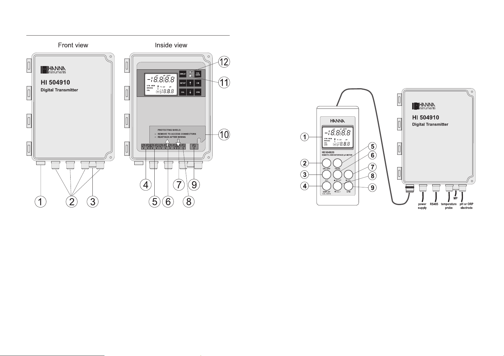
FUNCTIONAL DESCRIPTION
Keyboard and LCD for HI 504910 are normally provided
by HI 504920. To do this, HI 504920 has to be put
into terminal mode, by selecting code 90 in Setup
mode.
If the HI 504920 meter is not handy, the keyboard and
LCD inside the transmitter case can be used for configuring, calibrating and monitoring HI 504910.
1. Infrared optical interface for HI504920
2. Cable glands for 24 VDC power supply, for HI504
or computer workstation connection, for pH (or
ORP) electrode & temperature probe inputs
3. Cable gland for Matching Pin connection
4. Power supply input (24V AC/DC)
5. RS485 connections to HI504, PC, modem, GSM
module
6. Connections for Pt100/Pt1000 temperature sensor
7. Connection for Potential Matching Pin
8. Connection for electrode reference
9. Connection for pH or ORP electrode input
10. Protecting shield: remove to access connectors;
reattach after wiring.
11. Green status LED
12. Red status LED
6 7
1. Liquid Crystal Display
2. ON/OFF key, to turn the HI 504920 on and off.
3. ALT key, to activate alternate key functions
4. DISPLAY / CAL DATA key, to enter/exit the event scrolling mode, to view pH
buffer or °C while calibrating pH, and to view last calibration data (with ALT)
5. TXCAL key, for quick single point pH calibration
6. æ SETUP key, to move up or enter/exit the Setup mode (with ALT)
7. CAL key, to move right or enter/exit the calibration mode (with ALT)
8. CALT key, to move down (no alternate function for HI 504910)
9. CFM key, to confirm values.
The device can be restarted at any time by pressing CFM,
ALT and æ SETUP together (CFM first)
Page 5

Note Throughout this manual every reference to keyboard or LCD
refers to HI 504920 keyboard and LCD.
When using the HI 504910 internal keyboard and LCD,
refer to the below table to match keys.
SPECIFICATIONS
Range -2.00 to 16.00 pH
-2000 to 2000 mV
-30 to 130.0 ºC
HI 504920 HI 504910
DISPLAY DISPLAY
(ALT+) CAL DATA CAL DATA
(ALT+) SETUP SETUP
ææ
(ALT+) CAL CAL
CFM CFM
The two LCD’s have the same appearance; the only difference is the LOG tag blinking on the HI 504920 display to
indicate that the meter is operating in terminal mode.
Resolution 0.01 pH
1 mV
0.1 ºC
Accuracy ±0.02 pH
(@20°C/68°F) ±2 mV
±0.5 ºC
Typical EMC Deviation ±0.2 pH
±10 mV
±0.5 ºC
Temperature compensation Automatic or manual from -30 to 130 ºC
Temperature probe With 3-wire or 2-wire Pt100/Pt1000 sensor
(with automatic recognition and damage test)
Installation Category II
Power Supply 24V AC/DC ± 20%
Power Consumption 5 VA
Over Current Protection 400 mA 250V FAST FUSE
Infrared optical interface RS232, baud rate fixed to 2400
towards HI 504920
Data logging 6000 pH/ºC or ORP samples
Environment 0 to 50 ºC; max 85% RH non-condensing
Enclosure Fiberglass NEMA case 4X type
Dimensions 216 x 165 x 108 mm (8.5 x 6.5 x 4.25’’)
excluding mounting feet
Weight 1.5 kg (3.3 lb.)
8 9
Page 6
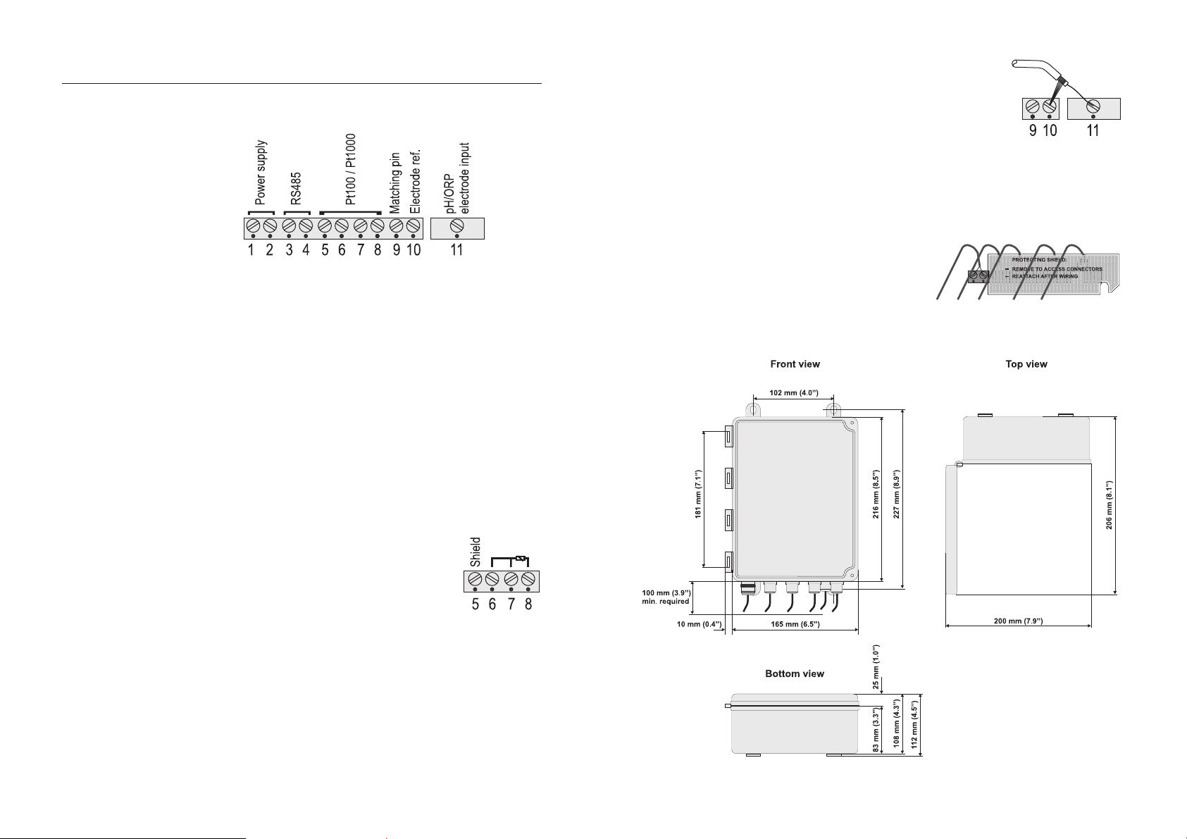
INSTALLATION
Note The serial interface of the HI 504910 Digital Transmitter is
Note The instrument automatically recognizes the sensor type (Pt100
• Remove the connectors protecting shield and wire the meter
as explained below.
• Power supply input (24V AC/DC): connect a 2-wire power
cable (with a minimum cross area of 0.75 mmq) to the
terminals #1 and #2.
If using a DC supply, connect the positive wire to the terminal #1.
• RS485 serial interface (for communicating with HI 504
controller or PC/modem/GSM module): connect a twisted
shielded cable to terminals #3 (B) and #4 (A).
optoisolated. Do not connect the serial cable shield to the
transmitter.
• Pt100/Pt1000 terminals: use these contacts to connect
the Pt100/Pt1000 temperature sensor for automatic temperature compensation of pH measurement.
In the case of shielded wire, connect the shield to pin #5.
In the case of a 2-wire sensor connect the Pt100/Pt1000 to pins #7
and #8, and short pins #6 and #7
with a jumper wire.
If the Pt100/Pt1000 has more than 2 wires, connect the
two wires of one end to pins #6 and #7 (pin #6 is an
auxiliary input to compensate for the cable resistance) and
one wire from the other end to pin #8. Leave the fourth
wire unconnected, if present.
or Pt1000).
• pH or ORP electrode: connect the
shield of the electrode coaxial cable
(electrode reference) to the terminal
#10, and the electrode coaxial
cable core to terminal #11.
To benefit from the differential (symmetrical) input, connect
the proper electrode wire or a cable with a potential matching pin (grounding bar) to the relevant terminal (#9).
If the matching pin is not available, short pins #9 and #10.
Note All connected cables should end with cable lugs.
Note After wiring, always reat-
tach the protecting shield.
DIMENSIONS
10 11
Page 7
CALIBRATION MODE
The calibration mode allows to calibrate the pH/ORP and
temperature inputs.
The instrument is factory calibrated for all these parameters.
Periodical calibration of the instrument is recommended, in
particular when greatest accuracy is required and at least biyearly.
The electrode can be calibrated over only one point but,
when possible, it is always good practice to perform a 2point calibration.
QUICK SINGLE-POINT pH CALIBRATION (through HI 504920)
A quick single point pH calibration at the pH value of the
solution monitored by HI 504910 transmitter can be performed. HI 504920 serves as a reference pH meter.
Unlike the usual calibration with buffers, this quick procedure is carried out without having to interrupt normal
measurement.
Note For better accuracy, from time to time it is recommended to
perform a 2-point calibration procedure, which allows to adjust not only the offset but also the slope of the pH probe.
• Connect the HI 504920 meter to HI 504910 through
the infrared interface cable.
• Immerse the pH electrode of the HI 504920 meter into the
solution measured by HI 504910, as close as possible to
the pH probe of HI 504910. Wait a few seconds for stabilization.
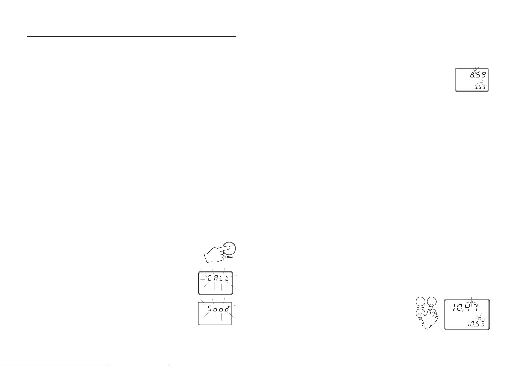
• When the HI 504920 meter displays
the pH measurement, press TXCAL (HI
504920 must be out of the HI 504910
terminal mode).
• The LCD will display “CALt” for a couple
of seconds to indicate that the calibration of the HI 504910 transmitter is in
progress.
• If the calibration is completed correctly,
the LCD will flash the “Good” message
for a few seconds. (Also the red LED
flashes once).
Note If the probe offset is outside the allowed limits, if the HI 504910
transmitter is configured for ORP measurement, or if some other
error occurs during calibration, the display will flash a “bAd”
message. Press TXCAL to return to normal mode and restart the
calibration procedure from the beginning.
• The primary LCD will then display the
pH reading of the HI 504910 transmitter, while the secondary LCD will
show the HI 504920 reading. Both pH
tags blink alternatively.
Note The two values may differ a little if the measured solution is
not stable. For an accurate calibration, perform the single
point procedure only when readings are stable.
• To exit the calibration mode, press TXCAL.
Note It is advisable to perform the entire calibration procedure
keeping the HI 504920 meter and the HI 504910 trans-
mitter connected through the infrared optical interface.
• It can happen that HI 504910 is positioned in a difficultto-reach place while the pH probe of HI 504920 is immersed in the solution: the two instruments will be not connected, and when the primary LCD shows the blinking
“CALt” message, the secondary display will show a countdown starting from 120 seconds. In this situation, the pH
probe can be taken out of the solution, while the interface
cable has to be connected to the HI 504910 transmitter
before the countdown reaches zero. Calibration then continues, and at the end of the procedure the pH tag of the
secondary LCD will not blink.
Note If the infrared cable is not connected before the end of the
countdown, the LCD shows the “tiMEout” message and the
calibration is not completed.
Note It is possible to check the HI 504910 pH reading against
the HI 504920 pH reading at any time, without calibrating
the HI 504910 transmitter.
• Press (ALT+) TXCAL.
• The primary display will
show the HI 504910 pH
reading, while the secondary LCD displays the
12 13
Page 8

HI 504920 pH reading. Both pH tags blink alternatively.
• To return to normal mode, press ALT and TXCAL.
• If a communication error between
the portable meter and the transmitter occurs, the primary LCD shows
the “rSEr” message: check the interface cable and connections.
• If the LCD shows “...”, verify that the HI 504910 transmit-
ter be configured for pH (not for ORP) measurement.
Note Whenever a pH or ORP calibration is performed by means of
HI 504920, the HI 504920 date and time are automatically set in HI 504910.
USING HI 504920 AS TERMINAL FOR HI 504910
Select code 90 in Setup mode and press CFM to confirm.
The HI 504920 enters the Terminal mode and the LOG tag
blinks on the LCD.
Note In this situation it is not necessary to connect the electrode to
the HI 504920 portable meter, which is working as keyboard and LCD for the HI 504910 transmitter.
To enter the calibration mode press
(ALT+) CAL.
The pH calibration can not be performed if the pH electrode
is broken or leaking or the reference electrode is broken or
dirty and an error is active. The ORP calibration can not be
performed if the “Reference electrode broken or dirty” error is
active. The temperature probe should be connected to the
instrument.
Initial Preparation
Pour small quantities of pH 7.01 (HI 7007) and pH 4.01
(HI 7004) or pH 10.01 (HI 7010) solutions into individual
beakers. If possible, use plastic beakers to minimize any EMC
interference.
For accurate calibration use different beakers for each buffer
solution, the first one for rinsing the electrode and the second
one for calibration. By doing this, contamination between
buffers is minimized.
• Enter the calibration mode, select
the pH calibration (by moving
through the menu with the æ and
keys), then press the CFM key.
• Choose the pH buffer set between the two available ones:
the standard set (4.01, 7.01, 10.01) and the NIST set (4.01,
6.86, 9.18). For the standard set confirm the “Std”; for the
NIST set confirm the “niSt” (use the æ and keys for select
between the two options).
Enter the correct password and press the CFM key. If a wrong
password is entered, the instrument returns to the previous
mode.
Note If the meter is set to measure ORP (setup item G.00), the pH
calibration, pH reading offset adjustment, and pH offset and
slope are not available. If the meter is configured for pH, no
ORP calibration can be selected.
Note Any calibration procedure can be aborted at any time by
pressing (ALT+) CAL, and the instrument returns to the previous mode.
pH CALIBRATION
To perform any pH calibration procedure, the instrument has
to be set as pH meter.
The meter can be calibrated through a one-point or twopoint calibration.
14 15
Two-point calibration
The default buffer set is the one used for last calibration,
even if the procedure was not completed.
• Once confirmed the set of buffer values, the primary LCD shows the
measured pH value, while the secondary LCD displays the first required buffer
value.
• Remove the protective cap from the pH electrode and immerse it into the buffer solution (e.g. pH 7.01) together
with the Potential Matching Pin and the temperature probe,
then stir gently.
Page 9
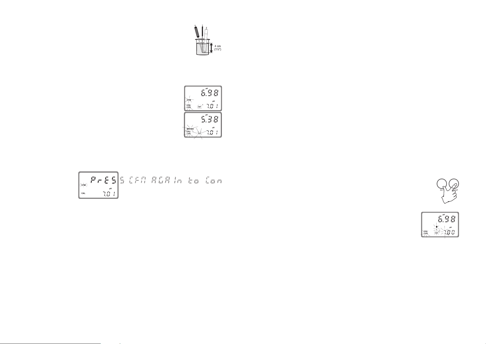
Note The electrode should be submerged ap-
proximately 4 cm (11/2’’) in the solution. The temperature probe has to be
located as close as possible to the pH
electrode.
Note When it is not possible to immerse the Potential Matching Pin
together with the pH electrode in the solution, disable the
differential input by setting setup item I.04 to “OFF”.
• When the reading becomes stable,
the probe indicator will stop flashing (after about 30 seconds), and if
the pH value is close to the selected
buffer, the “CFM” indicator will start
blinking, otherwise the “WRONG”
indicator, the pot and the BUF tags
will start blinking.
• Press the CFM key to confirm calibration. The meter will
show the scrolling message “Press CFM again to confirm
the current buffer or right to escape” (to prevent from confirming the calibration point inadvertently).
Pressing again CFM, the secondary LCD will display the
second expected buffer value.
• In the second case (pH value not close to the buffer) the
meter will remain in the same state until the reading becomes unstable or the calibration mode is quitted.
• For the second buffer value it is possible to choose between pH 4.01 and pH 10.01 (or pH 4.01 and pH 9.18 if
the NIST set has been selected). Use the æ or key to
switch between the two possibilities.
• Once selected the buffer, the procedure is the same as for
the first calibration point.
Note A time-out of 2.5 minutes is present for the pH electrode
response time. During calibration, if the pH reading is not
stable after 2.5 minutes, the device displays twice the scroll-
ing message “time-out”, then shows “WRONG” and it is not
possible to complete calibration.
• At the end of calibration, with the meter set as pH controller, the instrument checks if the offset is between -30 and
30 mV and the slope between 53.5 and 62 mV/pH. If the
values are not within these ranges, the message “OLd
ProbE” scrolls twice across the LCD. The electrode is still
working, but it is necessary to perform a cleaning procedure (see “Electrode conditioning and maintenance” and
“In-line Cleaning” sections) or replace it.
If the offset is outside the -60 to 60 mV range, the “dEAd
ProbE” message will scroll across the LCD and the corresponding error is activated. The electrode has to be replaced
as soon as possible because there is no reliability on the
measured pH values.
One-point calibration with manual selection of the calibration value.
A one-point calibration at a value different from the standard
buffer values is possible by entering the desired calibration
value. This is the actual pH value at the current calibration
temperature.
• Enter the pH calibration mode (no matter if
the standard or NIST buffer set is selected),
then press (ALT+) SETUP while the secondary LCD is displaying the first buffer value
(pH 7.01 or pH 6.86).
• The pH calibration value will switch
to 7.00, the first digit starts blinking
and it is possible to change its value
simply using the æ or key.
• Once selected the first digit value, press the key: the first
digit will be fixed and the second one will start blinking.
Pressing of the key repeatedly will result on circularly
moving on the secondary LCD.
• When the desired calibration value is reached (must be
within 0.00 to 16.00 pH), press the CFM key to confirm
and the calibration will proceed as described above.
• If the selected value is outside boundaries, the confirmation is not accepted and the first digit keeps blinking (waiting
for confirmation of a valid value).
16 17
Page 10
Note If (ALT+) SETUP are pressed instead of CFM, the calibration
Note Whenever a pH or ORP calibration is performed by means of
ORP CALIBRATION
value selection is aborted and the meter reverts back to a
two-point calibration.
HI 504920, the HI 504920 date and time are automatically set in HI 504910.
Check that the code 90 has been entered in Setup mode.
To perform ORP calibration it is necessary to connect an HI
931001 or HI 8427 simulator to the BNC socket.
The meter has to be set as ORP controller.
• A two-point calibration has to be performed: the first point
value is 0 mV and the second one can be chosen between
350 mV and 1900 mV.
• Enter the calibration mode, select the ORP calibration (use
the æ and keys to move through setup menu) and press
the CFM key.
• Set the HI 931001 or HI 8427 simulator to 0 mV.
• The primary LCD will display the current mV measure and the secondary
LCD will show the first calibration
point (0 mV).
• When the reading becomes stable,
if the ORP value is close to the calibration point, the “CFM”
indicator starts blinking; otherwise the “WRONG” indicator blinks and the “CAL” is fixed on.
• In the first case press CFM to confirm calibration. The
meter will proceed showing the scrolling message “Press
CFM again to confirm the current buffer or right to escape” (to prevent from confirming the calibration point
inadvertently). Pressing again CFM the secondary LCD will
display the second calibration point.
• In the second case (blinking “WRONG”) the meter will remain in the WRONG state until the reading becomes unstable
or the calibration mode is exited by pressing the CAL key.
• For the second calibration point it is possible to choose
between 350 mV and 1900 mV. Pressing the æ or key
the value on the secondary LCD will switch between the two
possibilities.
• Once selected the second calibration point, set the HI
931001 (350 mV) or HI 8427 (350 or 1900 mV) simulator to the same value and the calibration proceeds as for
the first point.
Note In ORP calibration there is no time-out.
Note Whenever a pH or ORP calibration is performed by means of
HI 504920, the HI 504920 date and time are automatically set in HI 504910.
TEMPERATURE CALIBRATION
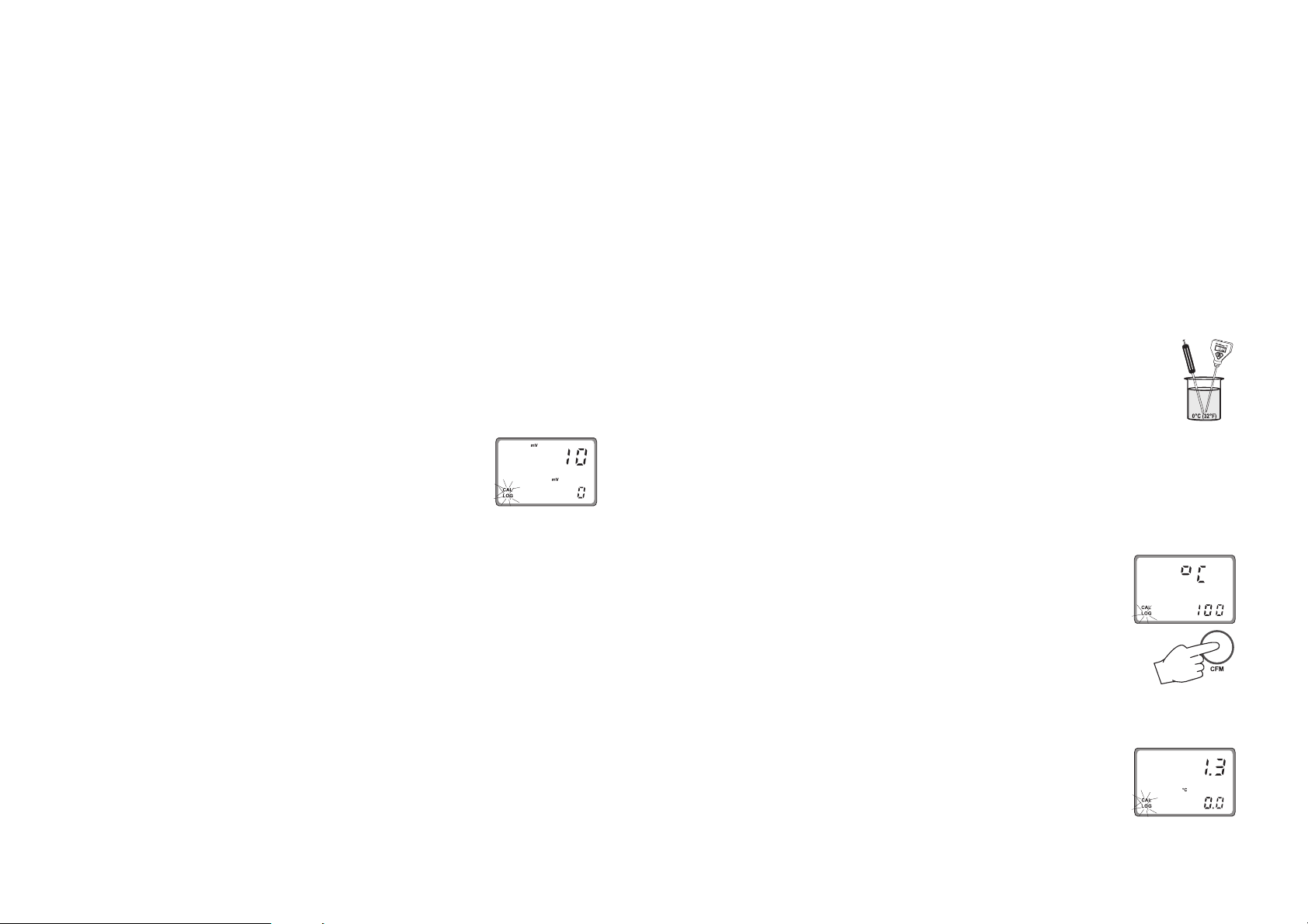
Check that the code 90 has been entered in Setup mode.
• Prepare a beaker containing crushed ice and water at 0°C
(32°F) and another one with hot water at 25°C (77°F) or
50°C (122°F).
• Use a Checktemp or another calibrated
thermometer with a resolution of 0.1° as a
reference thermometer.
• Immerse the temperature probe in the beaker with ice and water as near to the
Checktemp as possible.
Note The instrument can support Pt100 or Pt1000 temperature
sensor and calibration can be performed with anyone of these
two probes.
• After entering the calibration mode, move through the menu
(using the æ or key) to choose the temperature and the
correct kind of used probe; the primary
LCD shows “°C” and the secondary LCD
gives indication about the kind of probe
(“100” indicates a Pt100 probe, while
“1000” stands for a Pt1000 probe).
Press the CFM key to confirm selection.
• The calibration has to be performed over two points: the
first point has to be 0°C and the second one can be chosen between 25°C and 50°C.
Once confirmed the type of calibration,
the primary LCD will display the current
temperature measure and the secondary LCD will show the first calibration
point (0°C).
18 19
Page 11
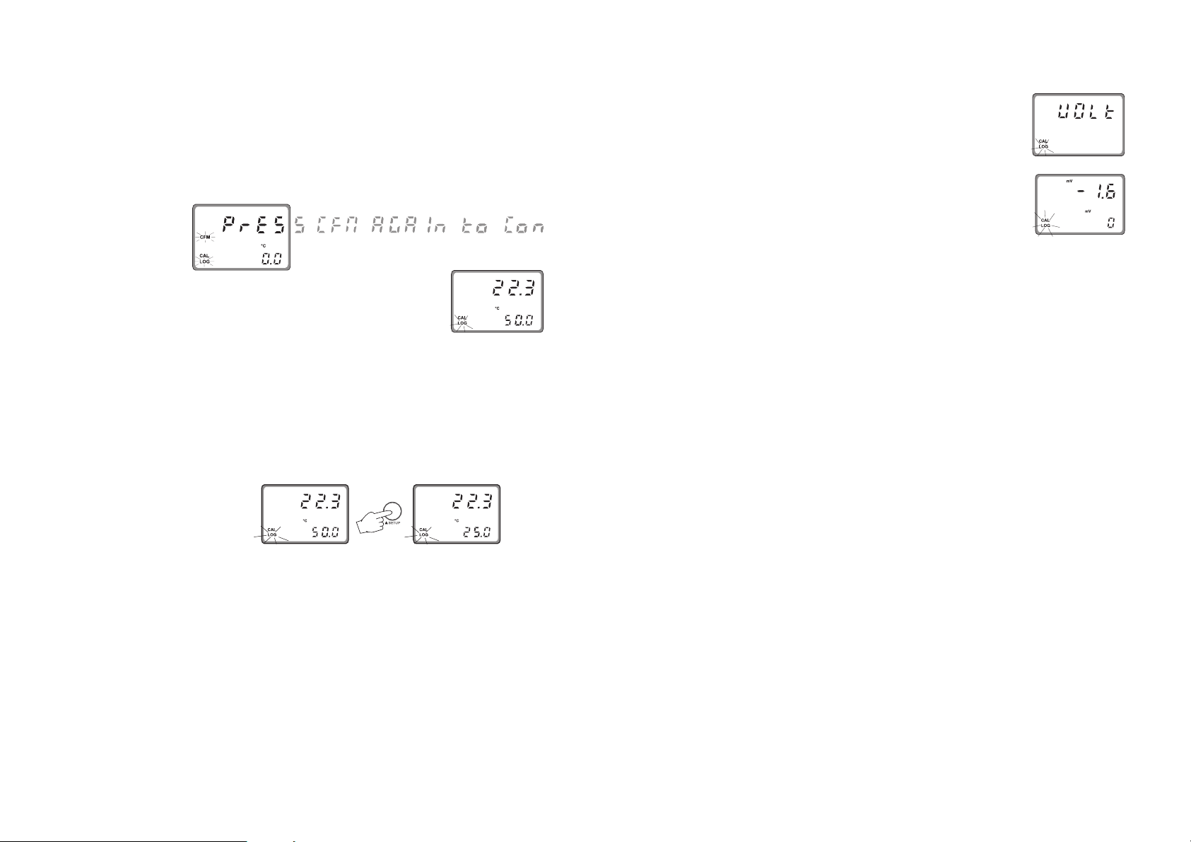
VOLT CALIBRATION
• When the reading becomes stable, if the temperature value
is close to the calibration point the CFM tag starts blinking, otherwise the WRONG indicator will flash.
• In the first case press the CFM key to confirm calibration.
The meter will proceed showing the scrolling message “Press
CFM again to confirm the current buffer or right to escape” (to prevent from confirming the calibration point
inadvertently).
• Pressing again the CFM key, the secondary LCD will display the second
calibration point.
• In the case the measured temperature is not close to the
calibration value, the meter remains in the WRONG status
until the reading becomes unstable or the calibration mode
is exited (by pressing the CAL key).
• When performing the second calibration point, it is possible to choose between two values, 25°C and 50°C. Pressing
the æ or key the value on the secondary LCD will switch
between the two possibilities.
• Once selected the value, immerse the temperature probe
in the second beaker as near as possible to the Checktemp
and the calibration procedure will be the same as for the
first point.
Check that the code 90 has been entered in Setup mode.
The instrument is factory calibrated; however the user may
also perform the Volt calibration, which is a procedure available for the instrument configured as pH meter only.
During pH measurements the instrument reads a mV value
from the electrode and then converts it into a pH value.
• Connect a HI 931001 or HI 8427 simulator to the BNC
socket.
• Once entered the calibration mode,
move through the menu with æ or
key, select the Volt calibration (the primary LCD shows “UOLt” message) and
confirm it by pressing the CFM key.
• After confirmation the primary LCD will
show the actual mV value and the secondary LCD will display the first
calibration point.
• The calibration is performed over two points, 0 mV and
350 mV.
• Set the HI 931001 or HI 8427 simulator to 0 mV.
• When the reading becomes stable, if the measured value
is close to the calibration point the CFM tag starts blinking, otherwise the WRONG indicator will flash.
• In the first case press the CFM key to confirm calibration.
The meter will proceed showing the scrolling message “Press
CFM to confirm the current buffer or right to escape” (to
prevent from confirming the calibration point inadvertently).
• Pressing again CFM the secondary LCD will display the
second calibration point.
• Set the HI 931001 or HI 8427 simulator to 350 mV and
follow the same procedure as for the first point.
• If the measured value is not close to the calibration value,
the meter will remain in the WRONG status until the reading becomes unstable or the calibration mode is exited (by
pressing the CAL key).
20 21
Page 12

SETUP MODE
The Setup Mode allows the user to set all needed characteristics of the meter.
Press (ALT+) SETUP and enter the password when
the device is in idle or control mode.
If the correct password is not entered, the user can only view
the setup parameters (except for passwords) without modifying them (and the device continues to acquire and transmit
measurements).
To each setup parameter (or setup item) is assigned a three
characters (one letter followed by two digits) setup code which
is entered and displayed on the secondary LCD. The first
character identifies the group of setup items, while the two
digits identify the particular item within that group.
The setup codes can be selected after password is entered
and CFM key is pressed. When CFM is pressed, the current
setup item is saved on EEPROM and the following item is
displayed.
The possible transitions in setup mode are the following:
ENTERING THE PASSWORD
• Press (ALT+) SETUP to enter the
• Enter the first digit of the pass-
setup mode. The primary LCD
will display “0000”, while the
secondary LCD shows “PAS”.
The first digit of the primary LCD
will blink.
word by using the æ or key.
Note The default password is set at “0000”.
ENTERING SETUP ITEMS
After confirmation of the password the
primary LCD will show the name of the
first setup group (see table) while the
secondary LCD will display the setup
code of the first item of the group.
• By pressing the æ or key it is possible to cycle through
the setup groups; the secondary LCD will always show the
code of the first item of the group.
• Once a group is selected, it is possible to choose an item manually.
Pressing the key, the first digit of
the setup code will start blinking.
Now it is possible to change its value
by pressing the æ or key.
• Pressing the key again, the first
digit will be fixed while the second
digit starts blinking and its value can
be changed as described above.
• By pressing the key again all the digits will be fixed.
• If CFM key is pressed, the selected item is confirmed; the
secondary LCD will show the setup item code while the
primary LCD will display the current item value.
If a fixed set of values is available for the selected item, use
the æ or key to switch between them.
• Then move to the next digit with
and enter a digit as described
above. Continue for the last two
digits.
• When the whole password has
been inserted, press CFM to
confirm it.
22 23
Otherwise, if a numeric value has to be entered for the
item, use the æ or key to change the value of the blinking digit and the key to cycle through the number’s
digits.
Page 13

• Once a value is set, press the CFM key to confirm. The
instrument will turn to the next item and the new item’s
value will be displayed on the primary LCD.
• If a wrong value is confirmed, the
WRONG indicator starts blinking,
the new value is not accepted and
the instrument will not switch to the
next item until a correct value will
be confirmed.
• Instead of selecting the item manually, it is possible to cycle
through all the items of a selected group by pressing repeatedly CFM key. The procedure to modify the item’s value
is the same described above.
If the last item of the group is reached, by pressing the
CFM key again the primary display will show the group
name and it will be possible to change the group by pressing the æ or key.
Note At any time for exiting the setup mode press (ALT+) SETUP. If
no modification has been confirmed, no setup item is
changed.
Note While in the setup mode, if no activity is performed for about
5 minutes after entering the setup mode, the mode is automatically exited and the instrument returns to the previous
mode.
The following table lists the setup codes along with the description of the specific setup items, their valid values and whether the
item is present for ORP mode.
Code Valid Values Default Present
for ORP
GENERAL (“GEnE”)
G.00 pH/ORP input “PH”, “OrP” (see note 4) “PH” yes
G.01 Temperature compensation “AtC”: Automatic “AtC” no
“USEr”: Manual (see note 3)
G.02 Manual or probe error -30 to 130.0 ºC 25.0 no
temperature (see note 3)
G.10 Factory ID 0000 to 9999 (see note 9) 0000 yes
G.11 Instrument ID 00 to 99 (see note 9) 00 yes
alias RS485 address
G.98 Calibration password 0000 to 9999 (see notes 1, 9) 0000 yes
G.99 General password 0000 to 9999 (see notes 1, 9) 0000 yes
OUTPUT (“OutP”)
O.30 Baud rate (see notes 9, 13) 1200, 2400, 4800, 9600, 19200 2400 yes
O.31 Modem calls answer enable “OFF”: disabled “OFF” yes
(see note 9) “On”: enabled
O.32 Modem country code Dialing code of a country where “000” yes
(see note 14) the modem of HI504902 is certified
INPUT (“InPU”)
I.11 Life check time “OFF”: life check disabled “OFF” yes
(see note 5) 1: 1 hour; 2: 2 hours; 4: 4 hours
I.12 Minimum pH probe slope 45 to 75 mV/pH 45 mV/pH no
I.13 pH electrode impedance “OFF”: disabled “On” no
test enable (see note 10) “On”: enabled
I.14 Reference electrode impedance “OFF”: disabled “On” yes
test enable “On”: enabled
I.15 Max ref. electrode impedance 0.5 to 100.0 kΩ 50.0 kΩ yes
I.17 Mains frequency (see note 11) 50 or 60 Hz 50 Hz yes
REAL TIME CLOCK (“rtC”)
r.00 Current day 01 to 31 (see note 9) from RTC (see note 12) yes
r.01 Current month 01 to 12 (see note 9) from RTC (see note 12) yes
r.00 Current year 2000 to 2099 (see note 9) from RTC (see note 12) yes
r.00 Current time 00:00 to 23:59 (see note 9) from RTC (see note 12) yes
24 25
Page 14

Notes
Code Valid Values Default Present
for ORP
CELLULAR/MODEM/PC CONNECTION (“PHOn”)
P.00 RS485 connection type “PC”=PC or modem connection “PC” yes
(see note 9) “CELL”=cellular module connection
P.01 PIN number (see note 9) 0000 to 9999 0000 yes
READING OFFSETS (“OFFS”)
F.00 pH or ORP actual value measured value -1.00 pH or measured yes
(see note 7) -200 mV to measured value value
+1.00 pH or +200 mV
F.01 pH or ORP reading offset -1.00 to +1.00 pH or 0.00 pH yes
adjustment -200 to +200 mV or 0 mV
F.10 Temperature actual value measured value -10.0 ºC to meas. value no
(for ATC only, see note 8) measured value +10.0 ºC (see note 7)
F.11 Temperature reading offset -10.0 to +10.0 ºC 0.0 ºC no
adjustment (for ATC only, see note 8)
TEST (“tESt”)
t.00 Display test “OFF”: To skip without testing “OFF” yes
t.02 EEPROM test “GO”: To start the display test
t.03 LEDs test
(1): The calibration password allows only calibrations, while the
general password allows everything (including calibration).
Obviously, the general password and the calibration password
cannot be viewed among other items when the “SETUP” key is
pressed without entering the right general password. The instrument is sold with a “0000” general password.
(2): When a wrong setup value is confirmed, the instrument
does not skip to the next setup item, but remains in the current item displaying a blinking “WRONG” indicator till the
parameter value is changed by the user (the same thing happens also for the setup code selection).
(3): See the “Temperature compensation” subsection for more
details on how the Automatic temperature compensation and
Manual temperature compensation work.
(4): Whenever the pH/ORP selection item is changed from pH
into ORP or vice versa all of the calibration and setup data
regarding pH (when changing to ORP) or ORP (when changing to pH) are kept. They are automatically restored if the mea-
sured magnitude is changed back later. The following setup
items cannot vary when changing from pH to ORP or vice
versa (because they are items strictly related to the instrument
and not to the measured magnitude): Factory ID, Instrument ID
alias RS485 address, Calibration password, General password,
Baud rate, Modem calls answer enable and Mains frequency.
(5): A life check error is generated if the pH reading does not
vary for more than ±0.10 pH within the time selected through
the “life check time” item (for pH) or mV reading for more
than ±10 mV within the same time (for ORP).
(6): When the instrument is configured for ORP measurements, some of the above items or item values are not anymore available to the user.
(7): “measured value” is the reading value with a null reading offset adjustment.
(8): If the device is set for MTC (item G.01 to “USEr”) then
items F.10 and F.11 cannot be modified nor seen. When item
G.01 is changed from “AtC” into “USEr”, item F.11 is automatically zeroed.
(9): These items do not vary when the pH/ORP input selection (“G.00”) is changed.
(10): This item must be set to “OFF” when an amplified
electrode is in use.
(11): Select the frequency of the mains power supply in your
country. This value is used to filter mains power supply noise
when performing the pH/ORP probe check.
(12): When the instrument is powered, RTC is checked to see
if an RTC reset occurred since last software initialization (if
one even took place). If this is the case, the RTC is initialized
with the default date and time: 01-01-2000-00:00. An
EEPROM reset does not affect the RTC settings.
(13): Only 2400 can be used for connection to HI 504.
(14): The modem present in the HI 504902 module is cer-
tified by Telecom to work in the following countries: Argentina, Australia, Austria, Belgium, Brazil, Canada, Chile,
China, Cyprus, Czech Republic, Denmark, Finland, France,
Germany, Greece, Hong Kong, Hungary, Iceland, India,
Indonesia, Ireland, Israel, Italy, Japan, Korea, Liechtenstein,
Luxembourg, Malaysia, Mexico, Netherlands, New Zeland,
Norway, Philippines, Poland, Portugal, Russia, Singapore,
Slovak Republic, South Africa, Spain, Sweden, Switzerland,
Taiwan, Turkey, United Kingdom, United States.
If your country is not present in the list, please contact your
Hanna dealer.
If the country code is shorter than 3 characters, fill the code
with zeros in front.
26 27
Page 15

MEASURE MODE
The measure mode is the normal mode for the instrument.
During measure mode, pH and temperature or ORP measurements are acquired and sent to HI 504 or to a PC with
HI 92500 or another software implementing the communication protocol described in this manual (see the “RS485
communication section”).
In a normal situation, during measure mode the green LED is
ON and the red LED is OFF (LEDs are located inside the
instrument case).
When the Setup mode or the Calibration mode are entered
through the HI 504920 (or through the HI 504910 inter-
nal keyboard), both the green and the red LEDs are ON.
The red LED ON warns the user that the HI 504910 is not
measuring and transmitting measurements.
Note In this situation, an HI 504 connected to HI 504910 will
be in hold mode.
In case of an error occurs in HI 504910, the green LED
turns OFF and the red LED flashes.
Note When measurements are in overflow, the internal LCD of the
HI 504910 or that of HI 504920 (in terminal mode) will
show the blinking upper or lower boundary value.
ERRORS
When an error occurs, the green LED turns OFF and an
alarm indication is given by the flashing red LED.
Below are listed all the errors with the correspondent error
code.
The error code is reported in the event log file, which can be
examined by means of the DISPLAY key while in normal measure mode (see the “Event log file scrolling” section). This is
necessary for identifying which error is active and makes the
red LED flash.
• Life check error (03) : The pH reading did not vary more
than ±0.10 pH (for pH) or the mV reading did not vary
more than ±10 mV within the time selected through the
“Life check time” setup item (I.11).
28 29
Clean and check the electrode.
• pH electrode broken or leakage (10) : The electrode
glass is broken or short circuits have been caused by moisture
or dirt.
Check pH probe and cable; replace them if necessary.
• Reference electrode broken or dirty (11) : The reference electrode is soiled or broken. Also the reference electrode or the matching pin could not have been immersed
in the solution.
Clean the electrode and replace it when necessary.
• Old pH probe (12) : The pH probe is old (offset outside
of ±30 mV or slope outside the range 53.5 to 62 mV/pH).
The electrode is still working, but it is recommended to
clean or replace it.
• Dead pH probe (13) : Offset is outside of ±60 mV or
slope outside the range 40 to 70 mV/pH. Readings are not
reliable.
Try to clean the probe; if the error persists after cleaning,
replace the probe immediately.
• No calibration (14) : The device has lost its calibration
due to an EEPROM reset.
Calibrate again all the magnitudes.
• Temperature probe broken (20) : Check the tempera-
ture probe wires and connections.
Replace the probe if necessary.
• Cellular error (50) : This is an error related to the HI
504900 GSM module. Check the power supply for HI
504900. Verify that the signal coverage is good.
• Power reset (90) : The device was restarted due to a
power failure.
• EEPROM corruption (91) : The EEPROM data is damaged. Reset the EEPROM, then recalibrate and reconfigure
completely the instrument.
• Watchdog reset (92) : The device was restarted due to a
watchdog reset or a manual reset done through the keyboard.
Page 16

pH/ORP PROBE CHECK
TEMPERATURE COMPENSATION
The pH electrode and the reference electrode for both pH
and ORP can be automatically monitored through HI
504910.
Setup items involved are I.13 (pH electrode impedance test
enable), I.14 (reference electrode impedance test enable) and
I.15 (maximum reference electrode impedance).
A “pH electrode broken or leakage error” (error code: 10) is
generated whenever the pH electrode impedance is less than
1 MΩ. This error can be due to breakage of the electrode
glass or short circuits caused by moisture or dirt.
A “reference electrode broken or dirty or not immersed” error
(error code: 11) is generated whenever the reference electrode impedance is greater than the value set in item I.15
(maximum reference electrode impedance range is 0.5 to
100.0 KΩ, default is 50.0 KΩ). This error can be due to
soiling of the reference electrode. It can occur also when the
reference electrode or the matching pin are not immersed in
the solution.
The pH electrode test is performed when the following conditions are satisfied:
• the test has been enabled through the setup item I.13;
• the device is in one of the following modes: measure, last
calibration data scrolling, event log file scrolling;
• the device is configured to measure pH.
Note If an amplified electrode is used, the pH electrode test
must be disabled by the user through the setup item
I.13.
The reference electrode test is performed when the following
conditions are satisfied:
• the test has been enabled through the setup item I.14;
• the device is in one of the following modes: measure, last
calibration data scrolling, event log file scrolling.
Note When testing or calibrating the instrument through a
pH/ORP simulator like HI 931001 or HI 8427, temporarily set the item I.13 to “OFF” and short the Matching pin and the Reference pin terminals.
If the setup item G.01 is set to “AtC” an automatic temperature compensation will be performed using the temperature
value acquired with the Pt100/Pt1000 input.
If the probe appears to be unconnected, or anyway it does
not give a valid temperature (temperature outside the -30 to
130°C range), the instrument will generate a broken temperature probe error. In this case the temperature will be
automatically set to the setup item G.02 (“Manual or probe
error temperature”) and the setup item G.01 will be automatically set to “USEr” (see below).
After that, the Pt100/Pt1000 input continues to be monitored
to track the Pt100/Pt1000 error closing.
The setup item G.01 is automatically changed back to “AtC”
when the Pt100/Pt1000 error is closed.
During error condition, if the user decides to start working in
manual mode (and so manually close the error), he has to
go in setup menu (item G.01), change the value to “AtC”
(automatic compensation) without giving confirmation, then
change again to “USEr” and finally give confirmation by
pressing the CFM key.
If the setup item G.01 is set to “USEr” a manual temperature
compensation will be performed, no matter whether the temperature probe is connected to the Pt100/Pt1000 input or not.
The start value for temperature, when entered the manual
mode, is the one stored at G.02 (“Manual or probe error
temperature”).
If the user wants to change the temperature value while in
manual mode, he has to press the æ or key. Pressing once
the æ key it will add 0.1°C to the actual temperature value,
while pressing the key it will subtract 0.1°C.
During these operations both the temperature value displayed
and setup item G.02 are updated (the last one is updated
with a maximum delay of 10s).
30 31
Page 17

LAST CALIBRATION DATA
If the instrument is set as pH meter, the following data about
the last calibration are stored in the EEPROM:
• Date
• time
• offset, in mV
• slope, in mV/pH
• up to two buffers.
If the instrument is set as ORP meter, the data stored in the
EEPROM are the following:
• Date
• time
• first calibration point
• second calibration point.
While displaying these data the HI 504910 continues to
acquire and transmit measurements.
To enter the last calibration data mode,
press (ALT+) CAL DATA.
If the meter has never been calibrated
or an EEPROM reset has occurred, no
calibration data is shown when CAL
DATA is pressed. The “no CAL” message will blink for a few seconds, then
the meter skips back to the previous
mode.
If the meter is configured to measure pH, once entered the
last calibration data, the following messages could scroll twice
on the primary LCD before showing the calibration date:
• “Old probe”
• “Dead probe”.
Otherwise the last calibration date will
appear on the primary LCD displayed
as DD.MM format, while the secondary display will show the last two digit
of the year.
Pressing the key, the meter will cycle through the following
steps in reverse order, i.e. beginning from last buffer.
Note At any time pressing the DISPLAY key or (ALT+) SETUP keys
the meter will return to the regular operating display.
• Press the æ or key to view the
time of last calibration. The secondary display will show “HOU” to
indicate “hour and minute” while the
primary LCD will show the time as
HH:mm format.
• Press the æ or key again to view
the offset in mV at the time of last
calibration. The secondary display
will show “OFF” to indicate “offset”.
• Press the æ or key again to view
the slope in mV/pH at the time of
last calibration. The secondary display will show “SLO” to indicate
“slope”.
• Press the æ or key again to view
the first memorized buffer at the time
of last calibration. The secondary
display will show “BUF1” to indicate
“first buffer”.
• Press the æ or key again to view
the second memorized buffer (if
present) at the time of last calibration. The secondary display will show
“BUF2” to indicate “second buffer”.
• Press the æ or key again to return to the first CAL DATA display
(date) at the time of last calibration.
32 33
Page 18

OFFSET AND SLOPE DIRECT SELECTION
It is possible to edit directly the values of the offset and the
slope to calibrate the instrument (for pH).
• Press (ALT+) CAL DATA entering the last calibration data
scrolling and then press (ALT+) SETUP.
• A password entry is required. If a wrong password is confirmed, the instrument reverts back to the normal mode.
• Otherwise, if correct password is confirmed, the LCD will appear as
follows: the secondary LCD shows
“OFF” to indicate “offset” while the
primary one shows offset default
value. The first digit on the primary
LCD is blinking, and it is possible to
change it by pressing æ or key.
• Pressing the key will move
to the second digit while the
first one will be fixed.
• If an offset calibration has been
made, the instrument will turn to
“slope” calibration (as indicated by
the “SLO” message on the secondary display. The slope value is shown
on the primary LCD and the first digit
is blinking to permit modifications).
• Press the æ or key to modify the value or key to move
to the next digit.
• Once selected the desired value, press CFM to confirm.
• After confirmation the instrument will turn back to normal
mode.
• If the slope is invalid, the ”WRONG” indicator will blink
on the LCD.
Note Press DISPLAY or (ALT+) CAL DATA to exit calibration. The
slope will be set to the default value (57.5 mV/pH).
Note After direct selection of offset and slope, calibration data can
be viewed by pressing (ALT+) CAL DATA while in normal
mode, but no pH-buffer values will be displayed during the
data scrolling on the LCD.
Note Whenever a pH or ORP calibration is performed by means of
HI 504920, the HI 504920 date and time are automatically set in HI 504910.
• Pressing repeatedly the key will move cyclically through
the digits of the primary LCD.
• Once selected the desired value, press CFM to confirm the
calibration offset.
• If the offset is invalid, the “WRONG”
indicator will blink on the display.
Note If DISPLAY or (ALT+) CAL DATA are pressed before CFM,
calibration is aborted without changing the previous calibration data.
34 35
Page 19

EVENT LOG FILE SCROLLING
The event log file is composed of maximum 100 recorded
events, which include errors, calibration events (type of calibration, date, time) and configuration changes.
To enter the event log file scrolling, press the DISPLAY key
while in normal measurement mode. Event scrolling does
not affect acquisition and transmission of measurements,
which continue normally.
If there is no event in the event log file, nothing happens
when the DISPLAY key is pressed.
Otherwise the primary display will show
the code of the last logged event while
the secondary LCD will show the number (index) of the event.
For each event the following is reported in any case:
• error code (displayed “Er” followed by the error number)
or setup item code (displayed “S” followed by the setup
item code) or “CALE” indication;
• event index (the oldest event has index 0, the latest event
has the higher index) shown on the secondary LCD.
In addition, the following information can be visualized:
• for errors: • start date
• start time
and if error is not on anymore:
• end date
• end time.
• for configuration changes:
• date of change
• time of change
• previous value
• new value
• for calibrations:
• date of calibration
• time of calibration
• calibrated unit (“pH”, “OrP”, “°C”, “UoLt”)
Once entered the log event scrolling, press the æ or key to
move through the events.
If the event is an error still active, the error code on the primary LCD will blink, otherwise it will be fixed.
To have a look at the additional information of a selected
event press the key (it will cycle through the additional
information).
Note To exit the log event scrolling, press the DISPLAY key.
Note The logged event information can be downloaded to a PC
through the HI 92500 application software.
36 37
Page 20

FAULT CONDITIONS
RS485 COMMUNICATION
The below fault conditions may be detected by the software:
• EEPROM data error
• serial communication internal bus failure
• dead loop.
EEPROM data error can be detected through EEPROM test
procedure at start-up or when explicitly requested using setup
menu, or during normal operational mode if a checksum
control fails.
When an EEPROM error is detected during normal mode, a
fault alarm is generated.
To close an error an EEPROM test (see “Selftest procedures”
section) or reset is required.
As soon as an EEPROM error is detected, the scrolling message “EEPROM reset needed - Press up button to reset stored
data or right button to ignore” will appear on the primary
LCD.
If the key is pressed, the instrument restarts operation, but
the device will be in Hold mode in any case (i.e. no measurement will be acquired).
If the æ key is pressed, all the data stored in the EEPROM are
erased and the default values loaded. After that, the device
must be completely recalibrated.
An internal bus error is detected when internal transmission
is not acknowledged or a bus fault occurs for more than a
certain number of unsuccessful transmission attempts (due
for example to a damage occurred to one of the ICs connected to the internal bus). After that the controller displays a
sliding message “Serial bus error”.
If the error is due to impossible communication, all the instrument tasks are stopped, the red LED blinks and the “Serial
bus error” slides forever (repair can not be postponed).
A software watchdog is provided in order to detect dead loop
conditions or other causes that make the software stuck. If it
happens, a software reset is generated after a time-out of 1
second.
38 39
SPECIFICATIONS
The digital transmission of measurements, error and status
information is implemented through an RS485 link.
The transmission can be directed to an HI 504 or to a computer workstation, which can be connected locally or remotely
through a modem connection.
RS485 standard is a digital transmission method that allows
long lines connections. Its current-loop system makes this
standard suitable for data transmission in noisy environments.
Data transmission from the instrument to the PC is possible with
the HI 92500 Windows
fered by Hanna Instruments and an RS232 to RS485 adapter
with Send Data Control connected to the serial port of your PC.
The user-friendly HI 92500 offers a variety of features such as
logging selected variables or plotting the recorded data. It also
has an on-line help feature to support you throughout the operation.
The readings logged into the HI 504910 internal memory
can be downloaded through HI 92500.
HI 92500 makes it possible for you to use the powerful means
of the most diffused spreadsheet programs. Simply run your
favorite spreadsheet program and open the file downloaded
by HI 92500. It is then possible to elaborate the data with
your software (e.g. graphics, statistical analysis).
To install HI 92500 you need a 3.5" drive and few minutes to
follow the instructions conveniently printed on the disk’s label.
Contact your Hanna Dealer to request a copy.
The RS485 standard is implemented in HI 504910 with the
following characteristics:
Data rate: up to 19200 bps (manually selected)
Communication: Bidirectional Half-Duplex
Line length: up to 1.2 km typ. with 24AWG cable
Loads: up to 32 typ.
Internal termination: none
Only 2400 bps can be used for connection to HI 504.
Windows® registered Trademark of “Microsoft Co.”
®
compatible application software of-
Page 21

CONNECTIONS
The connections for the 2-pin RS485 terminal provided are
as follows:
The instrument has no internal line termination. To terminate
the line, an external resistor equal to the characteristic line
impedance (typically 120Ω) must be added at both ends of
the line.
The RS485 can connect up to 31 Digital Transmitters on the
same physical network. All the units are slave devices and
are monitored and controlled by a single master station (typically an industrial PLC or PC).
Each unit is identified by its RS485 address, included in the
00 to 99 interval, which corresponds to the Instrument ID
configured through the setup item G.11.
(If the instrument does not recognize the address within the
command string, then it discards all the following bytes).
To avoid erroneous readings in Open-Line
conditions, pull-up and pull-down resistors should be connected as shown (Fail
Safe Open Line protection method).
The Fail-Safe resistors are connected only to one unit in the
line, and their value depends on the application and characteristic impedance of the connection cable.
If using HI 504 the fail safe resistors are already connected
on it, so they are necessary only if the HI 504910 transmitter
is connected to a PC.
The interface signals are optoisolated from the ground of the
instrument, the electrode and the temperature sensor.
Before connecting the meter to the computer, consult the computer manual.
The instrument can only work as a slave component. In other
words it can work as a remote terminal equipment answering
to the commands only.
RS485 PROTOCOL
This section is useful when connecting the HI 504910 trans-
mitter to a computer workstation or PLC, and an user-software
is used instead of HI 92500.
Commands are composed of four parts: addresses, command identifier, parameter, end of command.
Some of the commands are used when the master is requesting information from the controller, other when the master
wants to set a parameter in the instrument memory (RAM or
EEPROM).
The end of commands corresponds to the CR char (0x0d).
The master software must send the command string with a
maximum delay of 20 ms between each character.
The program on the master must not allow setting commands
other than keyboard commands if the general password has
not been entered. After the general password recognition
through the “PWD” command, a 1-minute time-out is let
before the instrument locks again, i.e. if the PC program
waits for more than 1 minute between two subsequent setting
commands, the second one is not fulfilled and the “PWD”
command must be issued again.
40 41
Page 22

Following is the complete list of commands available:
Command Parameter Remarks
NNMDR not available Requests firmware code
(always available)
STS not available Requests instrument status
NN
(LEDs, configuration change flag, etc.)
PHR not available Requests last pH reading
NN
(instrument configured for pH)
NNMVR not available Requests last mV reading
(always available)
TMR not available Requests temperature reading
NN
(always available)
CAR not available Requests all last calibration data
NN
(always available)
NNGET CNN Requests setup item C.NN
NNPWD C
NNSET CNNP
1C2C3C4
1P2C1C2C3C4
Sends the general password
(always available)
Sets setup item C.NN with
parameter P
1P2C1C2C3C4
(not available in setup mode)
EVF not available Requests event log file
NN
(always available)
EVN not available Requests new events
NN
(always available)
AER not available Requests active errors
NN
(always available)
NNKDS null Same as LCD key
NNKCD null Same as CAL DATA key
NNKUP null Same as æ key
NNKRG null Same as key
NNKST null Same as SETUP key
NNKCL null Same as CAL key
NNKDW null Same as key
NNKCF null Same as CFM key
(*)
(*) C
1C2C3C4
content; P
are ASCII chars corresponding to the setup item
are two additional bytes used for sign and half
1P2
digit as follows:
= + if>0
P
1
= - if<0
P
1
P
= 0 if most significant digit is not used
2
P
= 1 if most significant digit is used
2
When an item is shorter than 4 digits the Ci characters are
filled with blanks.
Following are examples for setup item format:
• item I.12, minimum pH probe slope
: parameter value =
56.2 mV, format = “+0562◊◊“, where ◊ indicates a blank;
• item F.11, temperature reading offset adjustment: parameter value = -0.3°C, format = “-00003”;
• item G.01, temperature compensation: parameter value
= “AtC”, format = “+0*AtC”.
For all items with a fixed set of choices, blank spaces on the
left of the value displayed are replaced with “*” (as many “*”
characters are needed to reach the maximum string length,
which is for example 3 for item I.11).
Blanks must be put on the tail for all items in order to have
always a total length of 6 characters (see the setup table).
The same parameter format used for setup item setting is
used also for setup item getting (i.e. when a
“NNGETCNN<CR>” command is received from the PC,
the reply “NN<STX>P
1P2C1C2C3C4
<ETX>” is sent back).
To perform a “NNSETCNN...” command the general password has to be sent in advance through the “NNPWD...”
command. See above for the password effectiveness time-out.
Some special setup items can not be set through RS485 commands. In particular it is not possible to access any setup
item that performs a test on the instrument and it is not possible to configure the baud rate (setup item O.30).
42 43
Page 23

The “NNSET...” and “NNGET...” commands when used for
password items, baud rate, F.00 and F.10 items, are answered
with “NN<CAN>”.
As soon as the instrument realizes that a command has been
received, it sends one of the following answers:
1) “NN”, ACK (char 0x06) if the instrument recognizes the set
command and performs the requested task;
2) “NN”, STX (char 0x02), DATA, ETX (char 0x03) if the received command is a request of data;
3) “NN”, NAK (char 0x15) if the instrument does not recognize the command or if the command syntax is wrong;
4) “NN”, CAN (char 0x18) if the instrument can not answer
to the request (because the given general password is
wrong, etc.)
The “NN” in the front of the answer is the Instrument
ID (“00” to “99”).
The time-out for the above answers is:
1) answer to “STS”, “PHR”, “MVR”, “TMR”, “AER” commands:
30 ms @ 19200 or 9600 bit/s, 40 ms @ 4800 bit/s, 60 ms
@ 1200 bit/s (for the complete answer, from STX to ETX).
2) answer to other commands: 2s (for the first character of the
answer).
The minimum delay between the last received and the first
sent character is 15 ms to allow the master to set itself into
receiving mode.
Here are descriptions of the answers format (for setup item
request see above):
The NNMDR request produces the following answer:
“NN<STX>FP504910VV--ABCD<ETX>”
where VV is the firmware version, e.g. ”10” for 1.0 and ABCD
is a special code used by HI 92500.
The NNPHR, NNMVR, NNTMR requests produce the fol-
lowing answer:
“NN<STX><ASCII string for a float>N<ETX>”.
The answer to the NNSTS command is:
“NN<STX>C
where C
1C2
1C2C3C4
are the ASCII representation of byte B1 described
<ETX>”
below (e.g. B1 = 0xF3 C1 = “F”, C2 = “3”), C3C4 are the
ASCII representation of byte B2 described below (e.g. B2 = 0x1D
C3 = “1”, C4 = “D”).
The meaning of B
B
bit 0 green LED (1: ON; 0: OFF)
2
and B2 is:
1
B2bit 1,2 red LED (bit 2 = 0 and bit 1 = 0: LED is OFF;
bit 2 = 1 and bit 1 = 0: LED is fixed
ON; bit 2 = 1 and bit 1 = 1: LED blinks)
B
bit 3 free for future use (and set to 0)
2
B
bit 4 free for future use (and set to 0)
2
B
bit 5 free for future use (and set to 0)
2
B
bit 6 free for future use (and set to 0)
2
B
bit 7 free for future use (and set to 0)
2
B
bit 0 free for future use (and set to 0)
1
B
bit 1,2 setup mode (bit 2=0 and bit 1=0: not in setup
1
mode; bit 2=1 and bit 1=0: setup mode, view
only; bit 2=1 and bit 1=1: setup mode, unlocked)
B1bit 3 calibration mode with device unlocked
(1: yes, 0: no)
B
bit 4 setup updated (set to 1 after a device power-up or
1
a device reset or a change in setup made through
the instrument keyboard; reset to 0 after receiving
a GET command)
B
bit 5 calibration made (set to 1 after a device power-up
1
or whatever complete calibration; reset to 0 after
receiving a CAR command)
B
bit 6 hold mode (1: ON, 0: OFF)
1
B
bit 7 free for future use (and set to 0)
1
The NNCAR request produces the following answer:
1) Instrument configured for pH:
If pH is not calibrated: “NN<STX>0<ETX>”
If calibration has been performed: “NN<STX>1 date time offset
slope1 slope2 buf1 buf2 N<ETX>”
The items in italic are separated by blank spaces and have the
following formats:
date ddmmyy (“020498” for April 2, 1998)
time hhmm (“1623” for 4:23 pm)
offset ASCII string for a float (example: “-0.2”)
slope1 ASCII string for a float (example: “62.5”)
slope2 ASCII string for a float (example: “60.4”)
44 45
Page 24

buf1 ASCII string for a float (example: “7.01”)
buf2 ASCII string for a float (example: “4.01”)
When some of the above items is missing (for example buf3 when
a 2-point calibration is performed) it is indicated with a “N” letter.
2) Instrument configured for ORP:
If mV is not calibrated: “NN<STX>0<ETX>”
If calibration has been performed: “NN<STX>1 date time N N N
buf1 buf2 N<ETX>”
The items in italic are separated by blank spaces and have the
following formats:
date ddmmyy (“020498” for April 2, 1998)
time hhmm (“1623” for 4:23 pm)
buf1 ASCII string for a float (example: “0”)
buf2 ASCII string for a float (example: “1900”)
None of the items above can be missing when the Instrument is
configured to measure and control ORP (as it always has to be
calibrated on two points).
The event log file is requested through the NNEVF<CR>
command. The maximum length of the event log file is 100
records. Here is the format for the answer:
If there is no generated error or event, the answer has the format
“NN<STX>0<ETX>”, otherwise:
“NN<STX>events_no event_code
start_date1 start_time
1
end_date1 end_time1 desA1desB1 ...
event_code
start_date2 start_time2 end_date2 end_time
2
desA2desB2 ...
event_code
start_datem start_timem end_datem end_time
m
desAmdesBm<ETX>”
where m is the number of events. Each token is followed
by a blank space, except the last one (“desB
”), directly
m
followed by the <ETX> character.
“events_no” is the number of events and its format is the
ASCII format for a number (“1”, “2”.... “99”, “100”).
The meaning of “start_date
” and “start_timei” is:
i
• for errors: date and time at which the error was generated;
• for setup events: date and time of a setup item change;
1
2
m
• for calibration events: date and time of a calibration.
The meaning of “end_date
” and “end_timei” is:
i
• for errors: end date and time if the error is not active anymore;
• for setup events: no meaning;
• for calibration events: no meaning.
The tokens format is described here below:
event_codei (errors) ER NN (e.g. “ER01” for Setp.1 alarm)
event_codei (setup) SCNN (e.g. “Sr01” for current month)
event_code
start_date
start_time
end_date
end_datei (not active err.) ddmmyy (“020798” for July 2, 1998)
end_time
end_time
desAi (errors) N (just the letter “N”)
desA
desAi (calibration) “XXPHX”, “XOrPX”, “XX^CX”, “UOLtX”
desB
desB
desBi (calibration) N (just the letter “N”)
desB
(calibration) CALE (always the string “CALE”)
i
i
i
(active errors) N (just the letter “N”)
i
(active errors) N (just the letter “N”)
i
(not active err.) hhmm (e.g. “0920” for 9:20 am)
i
(setup) P1P2C1C2C3C4(setup item format, prev. value)
1
(errors) N (just the letter “N”)
i
(setup) P1P2C1C2C3C4(setup item format, new value)
1
(cleaning) N (just the letter “N”)
i
ddmmyy (“010798” for July 1, 1998)
hhmm (e.g. “1735” for 5:35 pm)
See above in this section for the description of setup item
format “P1P2C1C2C3C4”.
Events are logged in the event log file in chronological order,
i.e. record number 1 refers to the oldest event. When the
event log file is full, the oldest event is replaced with the
oncoming one.
In order to speed up the updating of a remote monitor for the
events, the NNEVF<CR> command is supported by
NNEVN<CR>, the new event request command, which is
answered with the list of events occurred since the last reception of a NNEVF<CR> or NNEVN<CR> command.
Here is the format for answer to NNEVN<CR>:
“NN<STX>0<ETX>” if there is no new event, otherwise:
“NN<STX>new_events_no event_code
start_date
1
start_time1 end_date1 end_time1 desA1desB1 ...
event_code
start_date2 start_time2 end_date2 end_time
2
desA2desB2 ...
event_code
start_datem start_timem end_datem end_time
m
46 47
1
2
m
Page 25

desA
desBm<ETX>”
m
where m is the number of events. Each token is followed
by a blank space, except the last one (“desB
”), directly
m
followed by the <ETX> character.
“new_events_no” is the number of new events and its
format is the ASCII format for a number (“1”, “2”.... “99”,
“100”).
When a NNEVF<CR> or NNEVN<CR> command is
received by the instrument, the new events list is reset and
a following NNEVN<CR> command will be answered
with “NN<STX>0<ETX>” if no event took place in the
meantime. Thus, if the answer to NNEVN<CR> command is not received correctly, to update a remote monitor
for events, the NNEVF<CR> command for the whole
event log file must be used.
Note After a reset of the instrument, the answer to NNEVN<CR>
is the same as NNEVF<CR> (all events are new).
Note A modified record due to the closing of an error is not trans-
mitted by NNEVN<CR>, so again the NNEVF<CR> command is needed.
A small subset of the event log file, with information about
the active errors, can be downloaded through the
NNAER<CR> command. The answer is:
“NN<STX>C
where C
1C2C3C4C5C6
are the ASCII representation of byte B1 described
1C2
below (e.g. B1 = 0xF3 C1 = “F”, C2 = “3”), C3C4 are the
ASCII representation of byte B2 described below (e.g. B2 = 0x1D
C3 = “1”, C4 = “D”), C5C6 are the ASCII representation of
byte B3 described below (e.g. B3 = 0xBE C5 = “B”, C6 =
“E”).
The meaning of B
bit 0 free for future use (and set to 0)
B
3
B
bit 1 free for future use (and set to 0)
3
B
bit 2 free for future use (and set to 0)
3
B
bit 3 Life check error
3
B
bit 4 pH electrode broken or leakage
3
B
bit 5 Reference electrode broken or leakage
3
B
bit 6 Old pH probe
3
B
bit 7 Dead pH probe
3
, B2, B3 is:
1
<ETX>”
B
bit 0 No calibration
2
B
bit 1 Temperature probe broken
2
B
bit 2 free for future use (and set to 0)
2
bit 3 free for future use (and set to 0)
B
2
B
bit 4 Power reset
2
B
bit 5 EEPROM corruption
2
B
bit 6 Watchdog reset
2
B
bit 7 free for future use (and set to 0)
2
B
bit 0 free for future use (and set to 0)
1
B
bit 1 free for future use (and set to 0)
1
B
bit 2 free for future use (and set to 0)
1
B
bit 3 free for future use (and set to 0)
1
B
bit 4 free for future use (and set to 0)
1
B
bit 5 free for future use (and set to 0)
1
B
bit 6 free for future use (and set to 0)
1
B
bit 7 free for future use (and set to 0)
1
Each bit is equal to 1 if the correspondent error is ON
and equal to 0 if the correspondent error is OFF.
Note When a “NAK” or “CAN” char is sent, the whole instrument
reception buffer is cleared.
Note When the meter is receiving and answering to commands
other than “PHR”, “MVR”, “TMR”, “AER”, “STS”, the primary LCD of HI 504920 (in HI 504910 terminal mode) or
the primary LCD of HI 504910 displays “r485”.
48 49
Page 26

MODEM CONNECTION
A momodem connection can be established between
HI504910 and a remote computer over a telephone line. It
is possible to make two different type of remote connection:
• Over the GSM network, connecting the HI504900 cellular module to HI504910 RS485 port.
To enable the modem connection with HI504900 first it is
necessary to configure the cellular phone: set item P.01 with
the PIN code of the SIM card in the HI504900 module and
then set item P.00 to “CELL”. To complete the configuration
set item O.31 (“Modem calls answer enable”) to “On”.
Note A SIM card able to receive data calls must be used.
• Over a standard analog telephone line, connecting the
HI504902 modem module to HI504910 RS485 port.
To enable the modem connection with HI504902, first set
item P.00 to “PC”, then set item O.31 to “On” and finally set
item O.32 with the dialing code of the country where the
instrument is installed (for example “049” for Germany or
“001” for United States).
Note The HI504902 modem module must be connected to
HI504910 RS485 port (not necessary to telephone line) and
switched on while the previous configuration is carried out.
Note If the country code is shorter than 3 characters, fill the code
with zeros in front (for example the country code “49” must
be entered as “049” or the country code “1” must be entered
as “001”).
Note The modem present in the HI504902 module is Telecom
certified for working in all the following countries: Argentina,
Australia, Austria, Belgium, Brazil, Canada, Chile, China,
Cyprus, Czech Republic, Denmark, Finland, France,
Germany, Greece, Hong Kong, Hungary, Iceland, India, Indonesia, Ireland, Israel, Italy, Japan, Korea, Liechtenstein,
Luxembourg, Malaysia, Mexico, Netherlands, New Zealand,
Norway, Philippines, Poland, Portugal, Russia, Singapore,
Slovak Republic, South Africa, Spain, Sweden, Switzerland,
Taiwan, Turkey, United Kingdom, United States.
If your country is not present in the list, please contact your
Dealer.
The modem connection (both with HI504900 and
HI504902) allows the user to ask the controller from a remote position about its status, measurements and to change
some parameters.
Many devices can be monitored through a remote modem
connection, simply connecting all the devices and the modem or cellular module to the same RS485 network.
Only one device has to be configured through O.31 to answer to modem calls. That device will be the one controlling
the modem or the cellular module. To avoid conflicts, the
following must never be done:
• put more than one modem or cellular module in the same
RS485 network;
• set O.31 to “On” in more than one device in the same
RS485 network;
• set P.00 to “CELL” in more than one device in the same
RS485 network
• set O.31 to “On” in one device and P.00 to “CELL” in
another one within the same RS485 network;
• put a PC monitor within the RS485 network.
Provided the above, any Hanna instrument with RS485 port
can be attached to the network and monitored remotely.
50 51
Page 27

When making a call, after the data connection is established,
the “NNPWD...” command (where “NN” is the address of
the device controlling the modem, i.e. the one with O.31 set
to “On”) must be issued by the remote computer within 15
seconds. When the data connection is up, the RS485 protocol
for a remote connection is all the same as for a local network
(see the previous section). An automatic disconnection takes
place if no character is received in the RS485 network in 3-4
minutes.
Note When confirming the “CELL” option for setup item P.00, if the
LCD shows a blinking “WRONG” verify if:
- the SIM card is correctly inserted;
- the PIN number is correct;
- the signal coverage is good.
SELFTEST PROCEDURES
The selftest procedure can be made only entering the setup
menu and selecting one of the items of the “tESt” group (t.00
- t.03).
Note All the tests are made while in setup mode, where a time-out
is present. If no action is performed for about 5 minutes, the
mode is automatically exited and the instruments returns to
previous mode.
DISPLAY TEST
The display selftest procedure consists of lighting up all the
display segments together.
• To start the procedure select setup
item t.00 and an “OFF” blinking message will appear on the
primary LCD.
• Press the æ (or ) key once and
the message will switch to a blinking “GO”.
• Press CFM key to confirm or the
æ (or ) key again to return to
the previous status.
• If confirmation is given when the
“OFF” message is blinking, no
action is performed and it will move
to the next setup item (t.02).
• The display test is announced by a scrolling “Display test”
message.
• All the segments light up for a
few seconds and then switch off
before exiting the display test procedure and moving to the next
setup item (t.02).
52 53
Page 28

EEPROM SELFTEST
The EEPROM selftest procedure involves verifying the stored
EEPROM checksum.
• To enter the EEPROM test procedure select the setup item
t.02 and an “OFF” blinking message will appear on the
LCD.
• Press the æ (or ) key once and the message will switch to
a blinking “GO”.
• Press CFM key to confirm or the æ (or ) key again to
return to the previous status.
• If confirmation is given when the “OFF” message is blinking, no action is performed and it will move to the next
setup item (t.03).
• After confirmation, the selftest
procedure begins with the “tESt”
message blinking for a few seconds.
• During this time the instrument performs the EEPROM check,
and if the checksum is correct, the “Stored data good”
message will scroll on the primary display.
LEDs TEST
• To enter the LEDs test procedure select the setup item t.03
and an “OFF” blinking message will appear on the LCD.
• Press the æ (or ) key once and the message will switch to
a blinking “GO”.
• Press CFM key to confirm or the æ (or ) key again to
return to the previous status.
• If confirmation is given when the “OFF” message is blinking, no action is performed and it will move to the first
setup item of the group (t.00).
• Once confirmed the test, all the LEDs (if anyone was active) are switched off and the message “LEDs test - Press
CFM to escape” will scroll on the primary LCD during all
the test.
• Some keys are used to toggle LEDs ON and OFF:
- the DISPLAY key toggles the green LED;
- the (ALT+) CAL DATA keys toggle the red LED.
• To exit the test press the CFM key and the previous configuration of the LEDs is reestablished. The instrument will remain
in the setup menu and move to the first setup item of the
group (t.00).
• After that, the meter will remain in setup menu and move to
the next setup item.
• If the checksum fails, a fault alarm is generated and the
following message appears on the LCD: “Stored data error
- Press “UP” button to reset stored data or “RIGHT” button
to ignore”.
• If the key is pressed the instrument restarts operation,
but the device will be in Hold mode in any case (i.e. no
acquisition of measurements).
• If the æ key is pressed, all the data stored in the EEPROM
are erased and the default values loaded (a complete calibration of the instrument is needed).
• Once performed the selected action, the instrument will
remain in the setup menu and move to the next setup item
(t.03).
54 55
Page 29

pH VALUES AT VARIOUS TEMPERATURES
ELECTRODE CONDITIONING AND MAINTENANCE
Temperature has a significant effect on pH. The calibration
buffer solutions are effected by temperature changes to a lesser
degree than normal solutions.
For manual temperature calibration please refer to the following chart:
TEMP pH VALUES
°C °F 4.01 6.86 7.01 9.18 10.01
0
32
4.01
6.98
7.13
9.46
10.32
5
41
4.00
6.95
7.10
9.39
10.24
10
50
4.00
6.92
7.07
9.33
10.18
15
59
4.00
6.90
7.04
9.27
10.12
20
68
4.00
6.88
7.03
9.22
10.06
25
77
4.01
6.86
7.01
9.18
10.01
30
86
4.02
6.85
7.00
9.14
9.96
35
95
4.03
6.84
6.99
9.10
9.92
40
104
4.04
6.84
6.98
9.07
9.88
45
113
4.05
6.83
6.98
9.04
9.85
50
122
4.06
6.83
6.98
9.01
9.82
55
131
4.07
6.84
6.98
8.99
9.79
60
140
4.09
6.84
6.98
8.97
9.77
65
149
4.11
6.85
6.99
8.95
9.76
70
158
4.12
6.85
6.99
8.93
9.75
For instance, if the buffer temperature is 25°C, the display
should show pH 4.01, 7.01 or 10.01 at pH 4, 7 or 10
buffers, respectively.
At 20°C, the display should show pH 4.00, 7.03 or 10.06.
The meter reading at 50°C will then be 4.06, 6.98 or 9.82.
PREPARATION
Remove the electrode protective cap.
DO NOT BE ALARMED IF ANY SALT DEPOSITS ARE
PRESENT.
This is normal with electrodes and they will disappear when
rinsed with water.
During transport tiny bubbles of air may have formed inside
the glass bulb. The electrode cannot function properly under
these conditions. These bubbles can be removed by "shaking
down" the electrode as you would do with a glass thermometer.
If the bulb and/or junction are dry, soak the electrode in
HI 70300 Storage Solution for at least one hour.
If the electrode does not respond to pH changes, the battery
may be run down and should be replaced.
TEST MEASUREMENT
Rinse the electrode tip with distilled water.
Immerse the tip (bottom 4 cm / 1½") in the sample and stir
gently for approximately 30 seconds.
For a faster response and to avoid cross contamination of
the samples, rinse the electrode tip with the solution to be
tested, before taking your measurements.
STORAGE
To minimize clogging and assure a quick response time, the
glass bulb and the junction should be kept moist and not
allowed to dry out. This can be achieved by installing the
electrode in such a way that it is constantly in a well filled with
the sample (stream or tank).
When not in use, replace the solution in the protective cap
with a few drops of HI 70300 Storage Solution or, in its
absence, HI 7082 KCl 3.5M Solution.
Follow the Preparation Procedure above before taking measurements.
Note NEVER STORE THE ELECTRODE IN DISTILLED OR DEION-
IZED WATER.
56 57
Page 30

PERIODIC MAINTENANCE
Inspect the electrode and the cable. The cable used for the
connection to the controller must be intact and there must be
no points of broken insulation on the cable or cracks on the
electrode stem or bulb.
Connectors must be perfectly clean and dry. If any scratches
or cracks are present, replace the electrode. Rinse off any salt
deposits with water.
CLEANING PROCEDURE
General Soak in Hanna HI 7061 General Cleaning
Solution for approximately ½ hour.
Removal of films, dirt or deposits on the membrane/junction:
Protein Soak in Hanna HI 7073 Protein Cleaning So-
lution for 15 minutes.
Inorganic Soak in Hanna HI 7074 Inorganic Cleaning
Solution for 15 minutes.
Oil/grease Rinse with Hanna HI 7077 Oil and Fat Clean-
ing Solution.
IMPORTANT After performing any of the cleaning procedures rinse the
electrode thoroughly with distilled water and soak the electrode in HI 70300 Storage Solution for at least 1 hour before
reinstalling it.
- Make sure cable and connections are not damaged nor
lying in a pool of water or solution.
• Slow Response/Excessive Drift: soak the tip in Hanna Solution HI 7061 for 30 minutes, rinse thoroughly in distilled
water and then follow the Cleaning Procedure above.
• For ORP Electrodes: polish the metal tip with a lightly abrasive paper (paying attention not to scratch the surface)
and wash thoroughly with water.
Note With industrial applications, it is always recommended to
keep at least one spare electrode handy. When anomalies
are not resolved with a simple maintenance, change the electrode (and recalibrate the instrument) to see if the problem is
alleviated.
TROUBLESHOOTING
Evaluate your electrode performance based on the following.
• Noise (Readings fluctuate up and down) could be due to
clogged or dirty junction: refer to the Cleaning Procedure
above.
• Dry Membrane/Junction: soak in Storage Solution
HI 70300 for at least 1 hour. Check to make sure the
installation is such as to create a well for the electrode bulb
to constantly remain moist.
• Drifting: soak the electrode tip in warm Hanna Solution HI
7082 for one hour and rinse tip with distilled water.
• Low Slope: refer to the cleaning procedure above.
• No Slope:
- Check the electrode for cracks in glass stem or bulb
(replace the electrode if cracks are found).
58 59
Page 31

ACCESSORIES
pH CALIBRATION SOLUTIONS
HI 7004M or HI 7004L pH 4.01 Buffer Solution, 230 or 500 ml bottle
HI 7006M or HI 7006L pH 6.86 Buffer Solution, 230 or 500 ml bottle
HI 7007M or HI 7007L pH 7.01 Buffer Solution, 230 or 500 ml bottle
HI 7009M or HI 7009L pH 9.18 Buffer Solution, 230 or 500 ml bottle
HI 7010M or HI 7010L pH 10.01 Buffer Solution, 230 or 500 ml bottle
ORP SOLUTIONS
HI 7020M or HI 7020L Test Solution, 200-275 mV, 230 or 500 ml bottle
HI 7091M or HI 7091L Pretreatment Reducing Solution, 230 or 500 ml bottle
HI 7092M or HI 7092L Pretreatment Oxidizing Solution, 230 or 500 ml bottle
ELECTRODE STORAGE SOLUTIONS
HI 70300M or HI 70300L Storage Solution, 230 or 500 ml bottle
HI 7082 3.5M KCl Electrolyte, 4x50 ml
ELECTRODE CLEANING SOLUTIONS
HI 7061M or HI 7061L General Cleaning Solution, 230 or 500 ml bottle
HI 7073M or HI 7073L Protein Cleaning Solution, 230 or 500 ml bottle
HI 7074M or HI 7074L Inorganic Cleaning Solution, 230 or 500 ml bottle
HI 7077M or HI 7077L Oil & Fat Cleaning Solution, 230 or 500 ml bottle
OTHER ACCESSORIES
HI 504900 Hanna GSM module
HI 504902 Hanna RS485 modem
HI 504920 Remote user interface pH meter
HI 7611 Stainless steel Pt1000 probe with standard 1/2’’ external
threads on both ends for in-line and immersion installation;
5 m (16.5’) cable
HI 7621 Glass Pt1000 probe with external PG13.5 thread and 5 m
(16.5’) cable
HI 60542-0 1 set of O-rings for HI 60542 electrode holder
HI 60545-0 1 set of O-rings for HI 60545 electrode holder
HI 60501-0 1 set of O-rings for HI 60501 electrode holder
HI 605011 PVC mounting flange for HI 60501 electrode holder
HI 8427 pH / ORP Electrode Simulator
HI 931001 pH / ORP Electrode Simulator with LCD Display
HI 931002 4-20 mA Simulator
HI 8614 pH Transmitter
HI 8614L pH Transmitter with LCD
HI 8615 ORP Transmitter
HI 8615L ORP Transmitter with LCD
HI 92500 Windows
®
Compatible Application Software
ChecktempC Stick Thermometer (range -50 to 150°C)
ChecktempF Stick Thermometer (range -58 to 302°F)
HI 7610 Stainless steel Pt100 probe with standard 1/2’’ external threads
on both ends for in-line and immersion installation; 5 m
(16.5’) cable
HI 7620 Glass Pt100 probe with external PG13.5 thread and 5 m
(16.5’) cable
60 61
Page 32

pH AND ORP ELECTRODE HOLDERS
HI 60542 In-line electrode holder for direct pipe installation
HI 60545 Bypass loop electrode holder
HI 60501 Immersion electrode holder for tanks, vessels, baths and open
channels
Specifications HI 60542 HI 60545 HI 60501
Electrode Holder Material PVC PVC PVC
O-Ring Material NBR NBR NBR
Min. & Max. Temperature -10°C (14°F) & 60°C (144°F)
Min. Immersion Length --- --- 10 cm (3.9’’)
Max. Immersion Length 69 cm (27.1’’)
Max. Pressure 8 BAR (116 PSI) @25°C ---
or 3 BAR (43.5 PSI) @50°C
62 63
Page 33

pH AND ORP ELECTRODES
Hanna Instruments produces a wide range of pH and ORP electrodes specifically designed for needs of industrial uses. For a complete list of available electrodes visit our
web site at www.hannainst.com or contact your dealer.
The below table lists all the Combination, Flat tip, PVDF-body, polymer filled electrodes
with Matching Pin, operating pressure: up to 6 bar (87 psi)
CE DECLARATION OF CONFORMITY
Recommendations for Users
Before using this product, make sure that it is entirely suitable for the
environment in which it is used.
Operation of this instrument in residential areas could cause unacceptable
interferences to radio and TV equipment.
To maintain the EMC performance of equipment, the recommended
cables noted in the user's manual must be used.
Any variation introduced by the user to the supplied equipment may
degrade the instruments' EMC performance.
To avoid electrical shock, do not use this instrument when voltage at the
measurement surface exceed 24VAC or 60VDC.
(*) Available with GP sensor type only
(**) Fluoride-resistant glass sensor (F
(***) Not for ORP electrodes
-
<2g/L, temperature<60°C, pH>2)
To avoid damage or burns, do not perform any measurement in microwave
ovens.
External cables to be connected to the instrument should be terminated with
cable lugs.
64 65
Page 34

USER NOTES
66 67
Page 35

TECHNICAL SERVICE CONTACTS
Australia: Tel. (03) 9769.0666 • Fax (03) 9769.0699
China: Tel. (10) 88570068 • Fax (10) 88570060
Egypt: Tel. & Fax (02) 2758.683
Germany: Tel. (07851) 9129-0 • Fax (07851) 9129-99
Greece: Tel. (210) 823.5192 • Fax (210) 884.0210
Indonesia: Tel. (21) 4584.2941 • Fax (21) 4584.2942
Japan: Tel. (03) 3258.9565 • Fax (03) 3258.9567
Korea: Tel. (02) 2278.5147 • Fax (02) 2264.1729
Malaysia: Tel. (603) 5638.9940 • Fax (603) 5638.9829
Singapore: Tel. 6296.7118 • Fax 6291.6906
South Africa: Tel. (011) 615.6076 • Fax (011) 615.8582
Taiwan: Tel. 886.2.2739.3014 • Fax 886.2.2739.2983
Thailand: Tel. 66.2619.0708 • Fax 66.2619.0061
United Kingdom: Tel. (01525) 850.855 • Fax (01525) 853.668
USA: Tel. (401) 765.7500 • Fax (401) 765.7575
For additional Technical Support in your local language,
see www.hannainst.com
MAN504910R3 05/05
68
 Loading...