

Page 1
HI 504901
GSM Supervisor
Instruction Manual
Page 2
IMEI number.
Stick here the IMEI number label or write it down for your future reference.
________________________________________________________________
TABLE OF CONTENTS
WARRANTY . . . . . . . . . . . . . . . . . . . . . . . . . . . . . . 5
PRELIMINARY EXAMINATION . . . . . . . . . . . . . . . . . . 6
GENERAL DESCRIPTION . . . . . . . . . . . . . . . . . . . . . 6
MAIN FEATURES . . . . . . . . . . . . . . . . . . . . . . . . . . . 7
FUNCTIONAL DESCRIPTION . . . . . . . . . . . . . . . . . . 8
MECHANICAL DIMENSIONS . . . . . . . . . . . . . . . . . . 9
TECHNICAL DATA . . . . . . . . . . . . . . . . . . . . . . . . . 10
SAFETY INFORMATION . . . . . . . . . . . . . . . . . . . . . 11
MAINTENANCE & SAFETY TIPS . . . . . . . . . . . . . . . 11
INSTALLATION . . . . . . . . . . . . . . . . . . . . . . . . . . . 12
RS232 Auxiliary Port . . . . . . . . . . . . . . . . . . . . . . . 12
RS232 #1 and RS232 #2 Serial Port . . . . . . . . . . . 12
Digital Input (DIG IN) . . . . . . . . . . . . . . . . . . . . . 12
Disable SMS (DISABLE) . . . . . . . . . . . . . . . . . . . . . 13
Digital Output (DIG OUT) . . . . . . . . . . . . . . . . . . 13
RS485 Serial Port . . . . . . . . . . . . . . . . . . . . . . . . . 13
Power Supply Input. . . . . . . . . . . . . . . . . . . . . . . . 15
Battery . . . . . . . . . . . . . . . . . . . . . . . . . . . . . . . . 15
SIM Card Insertion . . . . . . . . . . . . . . . . . . . . . . . . 16
START-UP . . . . . . . . . . . . . . . . . . . . . . . . . . . . . . . 18
IDLE MODE . . . . . . . . . . . . . . . . . . . . . . . . . . . . . 19
INTERFACE CONFIGURATION. . . . . . . . . . . . . . . . 22
Application Software Installation. . . . . . . . . . . . . . . 22
Starting Configuration . . . . . . . . . . . . . . . . . . . . . 22
Local Configuration . . . . . . . . . . . . . . . . . . . . . . . 23
Remote Configuration. . . . . . . . . . . . . . . . . . . . . . 23
CONFIGURATION SETTINGS. . . . . . . . . . . . . . . . . 24
General Options Settings . . . . . . . . . . . . . . . . . . . 27
RS232 Options Setting . . . . . . . . . . . . . . . . . . . . . 30
RS485 Options Setting . . . . . . . . . . . . . . . . . . . . . 31
Digital I/O Options Setting . . . . . . . . . . . . . . . . . . 33
Page 3
SMS DELIVERY . . . . . . . . . . . . . . . . . . . . . . . . . . . 35
Alarm SMS . . . . . . . . . . . . . . . . . . . . . . . . . . . . . 35
Information SMS . . . . . . . . . . . . . . . . . . . . . . . . . 40
Digital Output Control . . . . . . . . . . . . . . . . . . . . . 45
PC COMMUNICATION . . . . . . . . . . . . . . . . . . . . . 46
Local Communication . . . . . . . . . . . . . . . . . . . . . 46
Remote Communication . . . . . . . . . . . . . . . . . . . . 47
PC Communication Protocol . . . . . . . . . . . . . . . . . 48
LED’s Status during PC Communication Session . . . 52
POWER FAILURE . . . . . . . . . . . . . . . . . . . . . . . . . . 53
FAULT CONDITIONS AND SELFTEST PROCEDURES . . 54
LED INDICATORS . . . . . . . . . . . . . . . . . . . . . . . . . 56
ERRORS PRIORITY . . . . . . . . . . . . . . . . . . . . . . . . . 58
TROUBLESHOOTING GUIDE . . . . . . . . . . . . . . . . . 59
Interface Configuration . . . . . . . . . . . . . . . . . . . . . 59
PC Communication . . . . . . . . . . . . . . . . . . . . . . . 60
SMS Delivery . . . . . . . . . . . . . . . . . . . . . . . . . . . . 61
ACCESSORIES . . . . . . . . . . . . . . . . . . . . . . . . . . . 63
APPENDIX . . . . . . . . . . . . . . . . . . . . . . . . . . . . . . 64
CE DECLARATION OF CONFORMITY. . . . . . . . . . . 65
USER NOTES . . . . . . . . . . . . . . . . . . . . . . . . . . . . 66
WARRANTY
Dear Customer,
Thank you for choosing a Hanna Product.
Please read this instruction manual carefully before using the
instrument. It will provide you with the necessary information
for correct use of the instrument, as well as a precise idea of
its versatility.
If you need additional technical information, do not hesitate
to e-mail us at tech@hannainst.com.
This instrument is in compliance with the
directives.
The HI504901 interface is warranted for two years
against defects in workmanship and materials when used for
their intended purpose and maintained according to instructions. This warranty is limited to repair or replacement free of
charge.
Damage due to accidents, misuse, tampering or lack of prescribed maintenance are not covered.
If service is required, contact the dealer from whom you purchased the instrument. If under warranty, report the model
number, date of purchase, serial number and the nature of
the failure. If the repair is not covered by the warranty, you
will be notified of the charges incurred. If the instrument is to
be returned to Hanna Instruments, first obtain a Returned
Goods Authorization number from the Customer Service department and then send it with shipping costs prepaid. When
shipping any instrument, make sure it is properly packaged
for complete protection.
© 2004 Hanna Instruments
All rights are reserved. Reproduction in whole or in part is prohibited without the
written consent of the copyright owner.
Hanna Instruments reserves the right to modify the design,
construction and appearance of its products without advance
notice.
5
Page 4

PRELIMINARY EXAMINATION
MAIN FEATURES
Remove the instrument from the packing material and examine it carefully to make sure that no damage has occurred
during shipping. If there is any noticeable damage, notify
your Dealer or the nearest Hanna Customer Service Center
immediately.
Note Save all packing materials until you are sure that the instru-
ment functions correctly. Any damaged or defective items must
be returned in their original packing materials together with
the supplied accessories.
GENERAL DESCRIPTION
HI504901 instrument is an intelligent interface between
Hanna meters with RS232 and RS485 port and an industrial
GSM cellular phone for sending SMS messages or connecting through a local or a remote computer with HI92500
Hanna application software.
HI504901 can acquire information about active alarms,
errors, current status and real time values with following Hanna
meters:
• HI8001 and HI8002 towards RS232 channel #1 and
RS232 channel #2 serial port;
• HI23 and HI24 series, towards RS485 serial port;
• HI700 and HI710 series, towards RS485 serial port;
• HI504 series, towards RS485 serial port;
• HI504910, towards RS485 serial port.
HI504901 device is also provided with one digital input
(typically an alarm relay) from “non-intelligent” instruments,
with only an alarm relay contact or another digital output
signal. HI504901 can be configured for all its parameters
and features through the HI504901SW Windows
patible application software provided with the instrument.
Two models are available:
• HI504901-1: Dual-band 900/1900 MHz GSM
• HI504901-2: Dual-band 900/1800 MHz GSM
®
com-
Power supply: 12VDC to 115VAC
power adapter (HI710005)
Power supply: 12VDC to 230VAC
power adapter (HI710006)
Here below are listed the main features of the HI504901
interface:
• GSM phone inside for Short Messaging Service (SMS) sending.
• Possibility of a wireless remote interface configuration or
connection to a computer workstation (equipped with a
modem) through the cellular phone inside.
• RS232 auxiliary port (PC config) for configuration or connection purpose with a local computer connected through
HI920010 cable.
• RS232 ports (channel #1 and #2) for communication towards Hanna meters with RS232 port.
• RS485 port for communication towards Hanna meters with
RS485 port, allowing connection of up to 32 instruments
on the same wire.
• Digital input port (typically connected to an alarm relay) to
acquire information from “non-intelligent” instruments.
• Digital output port, for which it is possible to change the
status (open/closed) through an appropriate SMS sent to
the interface.
• SMS enabling/disabling option through a dedicated port.
• LED indicators: four red LED’s are provided for signaling
error conditions or active alarms in the devices connected
to the interface through RS232 ports (#1 and #2), RS485
port or digital input, depending on interface configuration; one green LED and one red LED are provided to give
indication about SMS sending enable current status; two
green LED’s indicate the cellular phone signal quality; one
yellow LED is dedicated to the current status of digital output contact, and another yellow LED to the operating status of the cellular phone terminal.
• Real time clock.
• Diagnostic features.
• Internal backup battery which provides power supply in
case of mains power failure.
76
Page 5
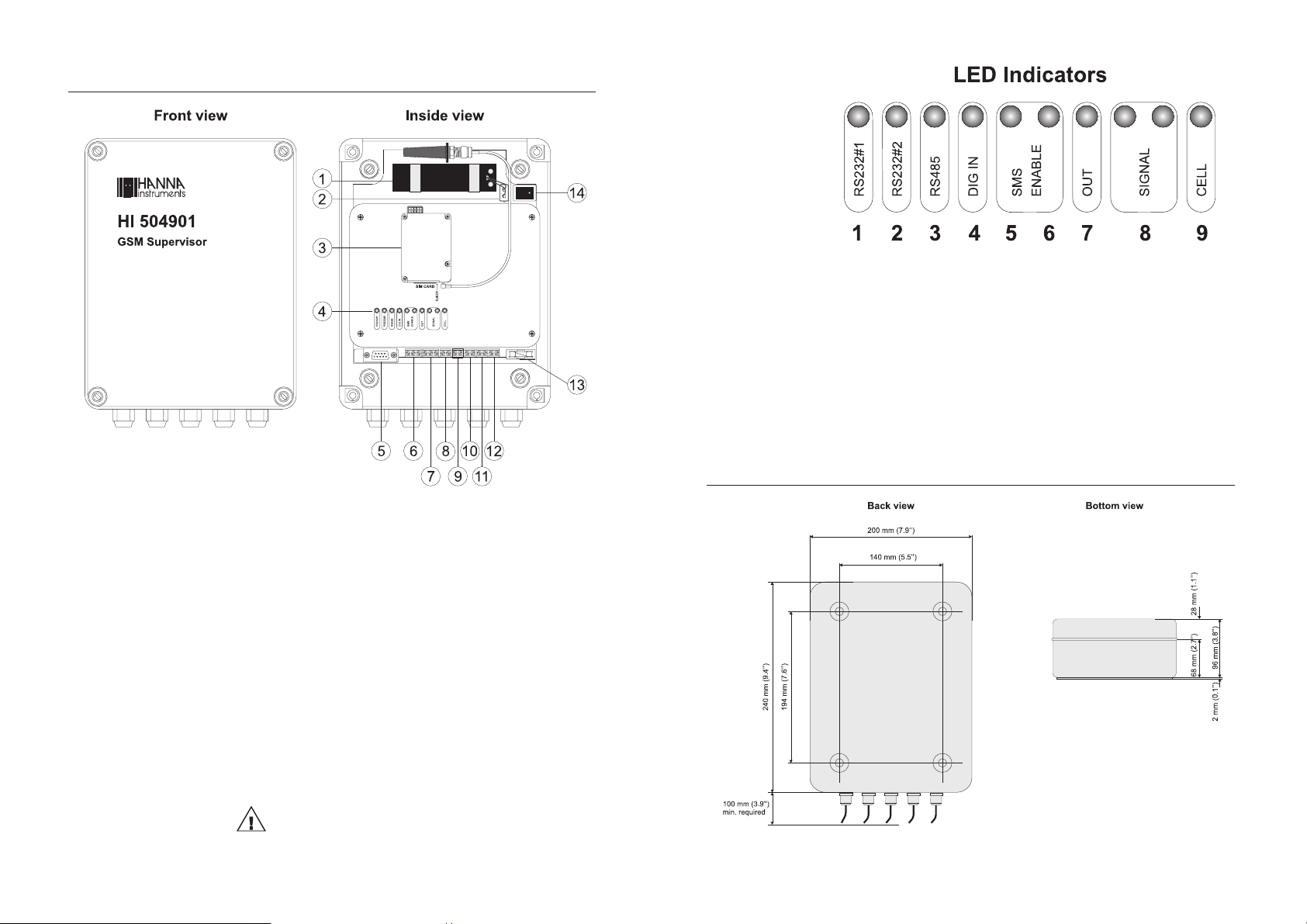
FUNCTIONAL DESCRIPTION
1. Backup battery (rechargeable, sealed lead-acid,
12V / 0.8Ah).
2. On board battery connector.
3. GSM module
4. LED indicators (see figure on next page).
5. RS232 auxiliary communication port
(for local PC communication only)
6. RS232 channel #1 serial communication terminal.
7. RS232 channel #2 serial communication terminal.
8. Digital input terminal to acquire external information.
9. Digital input terminal to disable SMS sending.
10. Digital output terminal.
11. RS485 serial communications terminal.
12. Power supply input (12 VDC).
13. Fuse (1 A).
14. Power ON/OFF switch.
1. RS232 serial port, channel #1, red LED.
2. RS232 serial port, channel #2, red LED.
3. RS485 serial port red LED.
4. Digital input port red LED.
5. SMS enable green LED.
6. SMS disable red LED.
7. Digital output yellow LED.
8. Cellular signal strength green LED’s.
9. Cellular operating status yellow LED.
MECHANICAL DIMENSIONS
Unplug the meter before any electrical connection.
98
Page 6
TECHNICAL DATA
Max output power 2 W for EGSM900; 1 W for GSM1800/1900
SIM interface 3V type SIM card
Antenna Dual-band antenna (900/1800/1900 MHz)
RS232 channels towards instruments
RS485 channel towards instruments
Digital input channel Supporting mechanical relays or open-collector outputs
Digital output channel Open collector output, 5 mA / 30V max.
RS232 auxiliary port towards PC
Installation Category I
Power Supply 12 VDC adapter & internal rechargeable battery
For connection of an instrument with RS232,
baud rate up to 9600 (limited by the instrument)
For connection of all instruments with RS485 in the
same bus; baud rate up to 9600
D-Sub female connector, baud rate up to 9600
(12V / 0.8 Ah) for backing up
SAFETY INFORMATION
Radio devices have limitations in the vicinity of electronic
devices.
• Unplug and turn off the unit in hospitals or near medical
devices like pacemakers or hearing aids. The module may
interfere with the operation of these devices.
• Unplug and turn off the unit when flying. Secure is so that
it can not be powered inadvertently.
• Unplug and turn off the unit near petrol stations, fuel
depots, chemical plants or blasting operations. The module can disturb the operation of technical equipment.
• Interference can occur if the device is used near televisions, radios or PCs.
In order to avoid possible damage, it is recommended to
use only the Hanna Instruments accessories. They have been
tested and shown to work well with this device. However,
accessories are not covered by the warranty.
Power Consumption 6 VA max.
Environment 0 to 50 ºC; max. 85% RH non-condensing
Enclosure ABS case, IP54
Dimensions 240 x 200 x 98 mm (9.4 x 7.9 x 3.9”)
MAINTENANCE & SAFETY TIPS
• SIM card: do not bend or scratch the SIM card or expose
it to static electricity.
• Wipe the module housing with a moist or antistatic cloth.
Do not use a chemical cleaning agent.
• Do not expose the GSM module to any extreme environment where the temperature or humidity is high.
• Do not attempt to disassemble the unit. There are no user
serviceable parts inside.
1110
Page 7
INSTALLATION
RS232 AUXILIARY PORT
HI504901 is provided with an auxiliary RS232 port (D-Sub
9-pole female plug) for connection to a local PC using an
HI920010 Hanna cable.
Note Use this RS232 auxiliary port only for local configuration of
the interface with HI504901SW software or local communication session with an instrument connected to the HI504901
interface (see “Interface Configuration” and “PC Communication” sections for details).
Note If the HI920010 Hanna cable is too short for your applica-
tion, please refer to “Appendix” for details about making a
longer communication cable.
RS232 #1 AND RS232 #2 SERIAL PORT
HI504901 is provided with two serial ports (channel #1
and channel #2) for communication with Hanna HI8001
and HI8002 controllers.
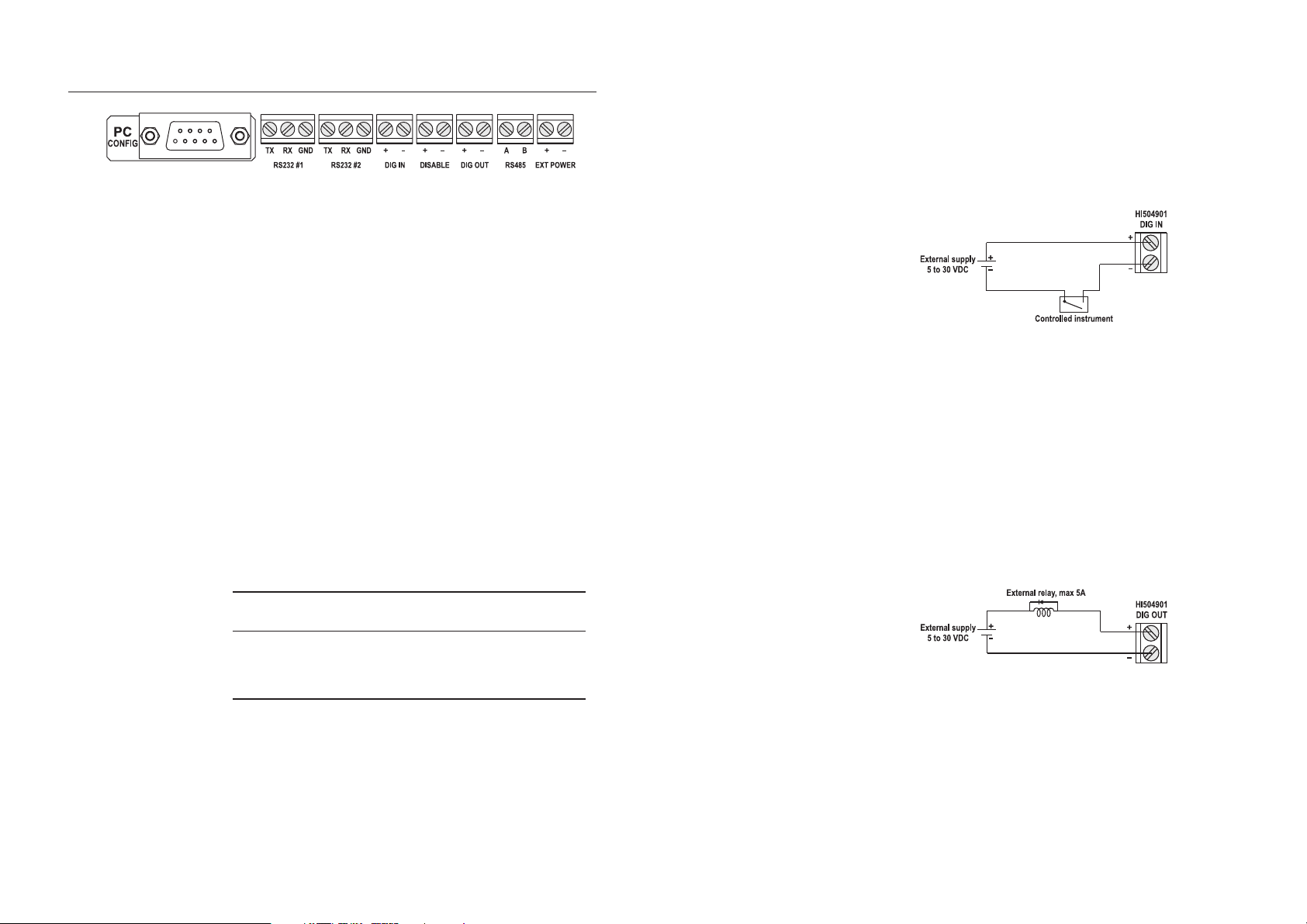
Each port is a 3-pin terminal: TX, RX and GND.
To connect the HI504901 interface to HI8001 or HI8002
controllers, use 9-pin D-Sub connector and shielded cable,
and follow the below indications.
from 5 to 30 V is applied or when it is disconnected.
This input can come from a relay contact or from an open
collector output (for example from a PLC).
Connect the positive pole of an external power supply to the
positive DIG-IN terminal; connect a command relay between
the negative pole of the external power supply and the negative DIG-IN (see also below diagram).
Note Never connect mains or AC voltage supply directly to the
DIG-IN terminal.
Note The digital input is optoisolated.
DISABLE SMS (DISABLE)
This input works as a digital input (see previous subsection)
and allows to ignore active errors and suspend SMS sending
during operations as calibration, start-up, maintenance, etc.
DIGITAL OUTPUT (DIG OUT)
This optoisolated terminal is an open collector output, which
can be used for external signaling through LED indicators or
small relays (see below diagram).
Note The RS232 standard allows to connect only one instrument to
DIGITAL INPUT (DIG IN)
HI8001/HI8002 HI504901
9-pin D-Sub male connector RS232-# terminal
Pin 2 TX
Pin 3 RX
Pin 5 GND
each serial port.
HI504901 is provided with a digital input, which can be
configured with HI504901SW software (see “Interface Configuration” section) to send an alarm SMS when a DC voltage
RS485 SERIAL PORT
HI504901 is also provided with a 2-pin RS485 terminal for
communication with Hanna HI23, HI24, HI700, HI710,
HI504 meters series and HI504910 digital transmitter.
The RS485 standard is a digital transmission method that
allows long line connections. Its current loop system makes
this standard suitable for data transmission in noisy environments.
1312
Page 8
Specifications:
The RS485 standard is implemented in HI504901 interface
with the following characteristic:
Data rate: up to 9600 (selected while configuring the
interface through HI504901SW software)
Communication: bidirectional Half-Duplex
Line length: up to 1.2 Km typical, with 24 AWG cable
Loads: up to 32 typical
Internal termination: none
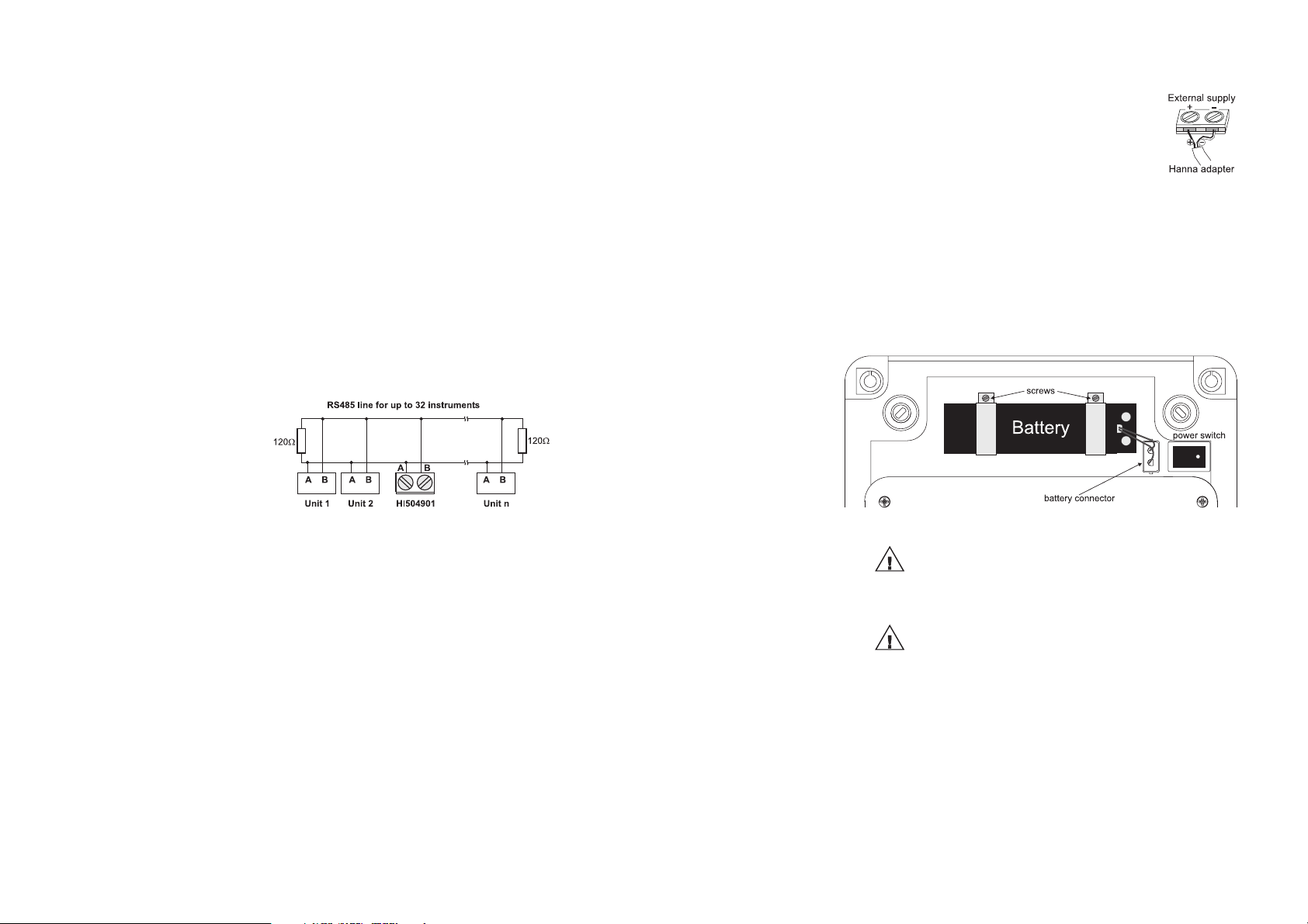
Connections:
The connections for the provided 2-pin RS485 terminal are
as shown on the below diagram.
The instrument has no internal line termination: to terminate
the line an external resistor equal to the characteristic line impedance (typically 120 Ω) must be added at both line ends.
HI504901 RS485 port can connect up to 32 instruments on
the same physical network, with a total line length up to 1.2
Km using a 24 AWG cable.
POWER SUPPLY INPUT
Use a 12VDC adapter (HI710005 or
HI710006) and connect the black wire to
the positive input terminal (marked “+”) and
the black & white wire to the negative one
(marked “-”).
All hard wiring can be accomplished through five watertight cable glands on the bottom side of the case,
by passing wires through the rubber grommets and
tightening the nuts.
Note All connected cables should end with cable lugs.
BATTERY
All the instruments connected to the RS485 port are “slave”
devices that are queried by the HI504901 supervisor. In
other words, the interface can work only as a “master” component, whereas the connected instruments work as remote
terminal equipments answering to the commands only.
Each instrument (except the HI504901 interface itself) is identified by its Process ID number, included within the 00 to 99
interval, which corresponds to the Process ID configured
through the proper setup item (please refer to the instrument
instruction manual for a complete explanation).
Note If an instrument does not recognize the address within the
command string, then it discard all the following bytes.
As additional feature, the HI504901 interface is also provided with internal Fail Safe Open Line protection method.
To minimize electromagnetic interferences, it is recommended
to use shielded and twisted pair cable to connect the units.
FOR SAVING BATTERY, THE HI504901 IS SUPPLIED WITH BATTERY NOT CONNECTED.
PLUG THE BATTERY CONNECTOR BEFORE
STARTING OPERATION.
Use only rechargeable sealed lead-acid battery with
12 V and 0.8 Ah capability.
To substitute battery, please follow below instructions:
1. turn off the HI504901: turn OFF the power switch and
disconnect the interface from the mains;
2. remove the screws on the bottom of the two battery clips;
3. disconnect the battery cable from its connector;
4. substitute the old battery with a new one;
5. fix back the two girdles by tightening the screws;
1514
Page 9
Note Pay attention that the battery cable is correctly connected to
Note If the interface is powered on immediately after a battery sub-
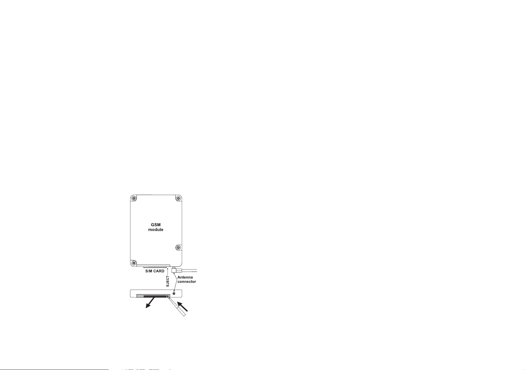
SIM CARD INSERTION
6. connect the battery cable to the connector;
7. connect the interface to the mains;
8. turn ON the power switch.
the battery connector, otherwise an alarm SMS will be sent
immediately after the start-up procedure (see “Fault Condition” section for details).
stitution, it is possible that an alarm SMS of “Battery failure”
is sent. Ignore that message and check if the error is still
active the day after. For avoiding this problem, connect the
unit to the mains and wait for at least 10 hours before turning
ON the power switch. In this manner the new battery can be
charged.
Before using the HI504901, insert a SIM card.
• Press the SIM card holder ejector on the cellular module
by using a sharp item (for example, a pen);
• Insert the SIM card in the holder and push it back in the
housing.
Note If the HI504901 has to be used for sending alarm SMS, be
sure that the SIM card can support voice calls. If the
HI504901 will be used for remote connection session, be
sure that the SIM card supports data calls. Please contact the
cellular network operator for information about SIM active
services.
Note Do not remove the SIM card while voltage is applied to cel-
lular phone. Before removing the card, turn off the interface.
Failure to do so may seriously affect the serviceability of the
HI504901.
1716
Page 10
START-UP
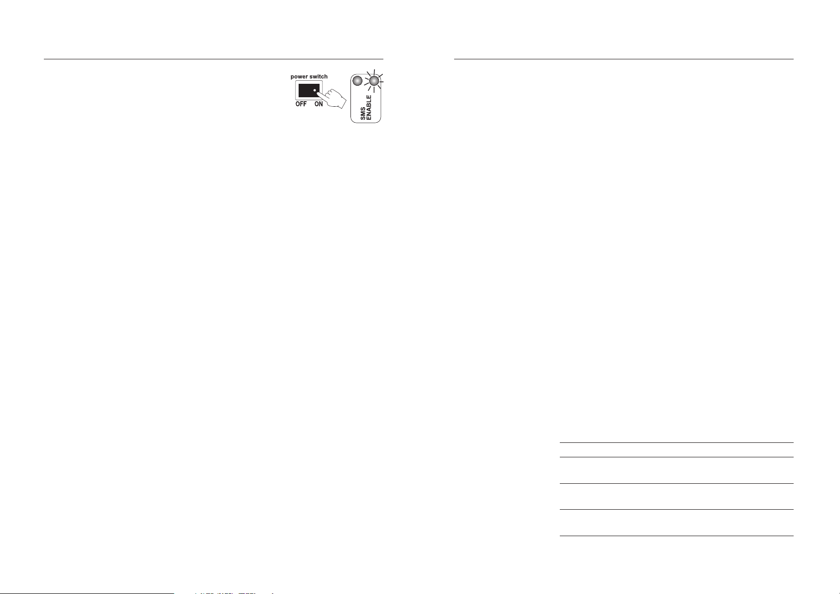
IDLE STATE
Turn ON the power switch (#14
on page 8): the red SMS disable
LED lights up and will stay in this
state until the start-up procedure
ended and the idle mode is entered.
During start-up procedure the Real Time Clock (RTC) is
checked to control if a reset occurred since last software initialization. In this case, the RTC is initialized with the default
date and time 01/01/2000 - 00:00. An EEPROM reset does
not affect the RTC settings.
The EEPROM is also checked to control if it is new. In this
case, the default values are copied from ROM and the device enters normal mode. Otherwise an EEPROM checksum
test is performed (the same is performed periodically during
EEPROM selftest procedure, see “Fault Condition and Selftest
Procedure” section for more details).
If checksum is not correct, the proper EEPROM error LED
indication will be given as soon as the Idle state is entered.
During start-up, the internal cellular phone is turned ON
and an initialization procedure is performed to insert PIN
code (when needed) and make network registration for enabling incoming and outcoming calls. Moreover, the
telephone answering service is disabled to avoid automatic
network call forwarding if interface is busy and can not serve
immediately incoming call.
Initialization procedure can last up to 30 seconds if no problem occurs, otherwise some more time could be needed and
proper cellular LED indication will be given in idle state.
When the start-up procedure is complete, the interface enters
the idle state.
Note When the HI504901 is turned ON for the first time, it is
possible to get a cellular error indication. This can happen if
the SIM card requests a PIN code to be registered in the
network and the interface was not yet configured (see “Local
configuration” section for details).
The idle state is the normal operation state for the HI504901
supervisor. While in idle state, the following main tasks are
fulfilled:
• Management of incoming remote connection and configuration requests (see “Interface configuration” and “PC
communication” sections for details);
• Management of incoming local connection and configuration requests;
• Polling procedure of connected devices;
• Diagnostic selftest procedures: battery test, cellular phone
test, EEPROM corruption data test (see “Fault condition”
and “SMS delivery” sections);
• Processing of incoming SMS’s for digital output control (if
enabled) and information SMS’s request (see “SMS delivery” section);
• Sending of alarm SMS’s or information SMS’s upon user
request (see “SMS delivery” section).
When in idle state, the HI504901 can perform periodically
some diagnostic selftest procedures as: internal backup battery test, cellular phone test, EEPROM corruption data test. If
one of these tests does not pass, the interface advises the
user with a visual indication about the problem using the red
and green SMS enable/disable LED’s. Please refer to “Fault
conditions and Selftest Procedures” section for more complete indications about interface related fault conditions.
Moreover, every 30 seconds the two green LED’s for cellular
phone signal are updated with the current signal strength,
and the indication meanings are listed in the table below:
LED Status Meaning
Cell Signal 1 (green) OFF No signal or
Cell Signal 2 (green) OFF cellular error found
Cell Signal 1 (green) ON Medium signal
Cell Signal 2 (green) OFF
Cell Signal 1 (green) ON Strong signal
Cell Signal 2 (green) ON
1918
Page 11

Also the digital output status LED is updated with the current
status of the digital output contact. The digital output contact
status can be changed by the user only by sending the proper
SMS to the interface. The below table shows the digital output
LED indication depending on the digital output status:
LED Status Meaning
Digital Output OF F Dig.output contact open
(yellow) ON Dig.output contact closed
Note The status of the digital output contact is saved in HI504901
internal memory, so that the digital output is set to the correct
value in case of a reset or after a start-up of the interface.
During polling procedure all devices connected to the interface through RS232, RS485 serial ports and digital input port
(if correctly configured, see “Interface Configuration” section) are periodically queried to acquire their current status,
measurement values and active alarms. The delay between a
query operation and the following one is user selectable, and
can vary from 1 to 10 minutes (see “Query Delay” field and
“Interface Configuration” section).
If many devices are connected to the RS485 link and the
cellular phone interface can not interrogate all the devices
within the selected delay time, then the actual interval becomes longer than the set value.
When polling devices procedure is completed, if some alarm
is active on the device connected to an RS232 port channel,
the corresponding LED (#1 and #2 on page 9) will light up;
besides, the RS485 serial port LED (#3 on page 9) lights up
if an alarm is active at least in one of the instruments connected to the RS485 port (up to 32 devices can be connected
on the same RS485 port); the digital input port LED turns on
or off depending on the user-selected logic for closed contact (if control of digital input port was user-enabled during
last interface configuration).
Moreover, if an active alarm found in a device connected to
the HI504901 matches with one of those selected by the
user during last interface configuration, or if the digital input
status matches with the condition selected for triggering an
alarm message, then one (or more) SMS(s) are immediately
submitted by the HI504901 to the set cellular phone
number(s) (see SMS delivery” section).
Note The “Query Delay” time value fixes the maximum delay be-
tween an alarm occurrence in a device and the related alarm
SMS sending by the interface.
SMS can be submitted by the HI504901 supervisor only if
the SMS sending feature is enabled through an external switch
(see further on for details); if the SMS sending is disabled,
then no message will be sent upon alarm or fault condition
on connected devices.
Note To make the HI504901 queries the connected devices and
sends SMS’s, it is necessary to configure the interface, otherwise no polling procedure can take place and no alarm notification will be given by the interface. HI504901 can not
automatically detect which instruments are connected to the
interface; moreover, the user must select for which type of
alarms he wants to receive warning SMS’s.
While in idle state, the SMS sending feature can be disabled
or enabled by the user at any time, by simply closing (or
opening) the proper external switch. If no error indication is
already active, then the red and green LED’s (# 5 and #6
on page 9) keep indication about the SMS sending enable/
disable status:
External Switch LED Status Meaning
Open SMS enable (green) ON SMS sending enabled
SMS disable (red) OFF
Close SMS enable (green) OFF SMS sending disabled
SMS disable (red) ON
Note Sometimes the updating of LED indication about SMS send-
ing status can take a few seconds after changing the external
switch status by the user. This happens if the interface is busy
while performing procedures as polling devices, SMS sending, incoming call processing, etc.
While in idle state, HI504901 can serve also incoming request for configuration or PC communication session
activation (both local and remote), but remote sessions (both
configuration and PC communication) can take place only if
no cellular errors are active on the interface.
2120
Page 12

INTERFACE CONFIGURATION
The HI504901 supervisor is not provided with keyboard or
display for user interfacing purpose. For first installation and
for successive changes of the system configuration, it is necessary to use the HI504901SW Windows® compatible
application software provided with the instrument.
APPLICATION SOFTWARE INSTALLATION
To install the HI504901 configuration software on the computer, it is necessary a 3.5’’ drive. Insert the disk #1 in the
floppy disk driver, execute setup.exe and then follow on-line
instructions.
After installation, run the configuration software by simply
double-clicking on HI504901SW icon and starting the configuration procedure.
STARTING CONFIGURATION
Before starting the configuration procedure, turn the
HI504901 on and make sure it ended the initialization procedure (see “Start-up” section).
The HI504901 supervisor can be configured in two different
ways: “Local configuration” and “Remote configuration”,
which can be selected on “Connection setting” window while
running the application software.
Find here below a complete list of LED’s status during configuration procedure:
LED Status Meaning
RS232 channel # (red) OFF --RS485 channel (red) OFF --Digital input (red) OFF --SMS enable (green) OFF -- SMS enable (red) ON -- Digital output (yellow) ON or OFF indication about digital output previous
status (ON: contact closed, OFF: open)
Cell Signal Quality (2, green) OFF & OFF updated only when “Phone Status”
ON & OFF button is pressed on application software
ON & ON while running on PC connected with
HI504901 device
Cell Status ON or OFF or cellular phone real time operating
blinking status (fast blinking if a remote
connection is taking place)
LOCAL CONFIGURATION
The “Local” configuration is the only one allowed for the first
configuration of HI504901 supervisor. This type of configuration takes place between the HI 504901 device and a PC
(placed near) with HI504901SW installed, through a serial
cable connection.
To connect the HI504901 supervisor to the PC, use an
HI920010 cable. Plug one connector to the HI504901
device RS232 auxiliary connector (PC config port) and the
other one to a serial port of the PC. Before connecting the
supervisor to the PC, read the computer manual.
To proceed with local configuration, select the “Local” connection type on HI504901SW “Configuration Settings”
window, and on “Serial communication port” section the PC
COM port to which the serial cable is connected. Then press
“OK” to proceed (see “General Settings” section).
Note The first configuration of HI504901 must be done through
a local configuration because it is necessary to set up the
SIM card PIN code and at least one cellular phone number
for the alarm SMS sending.
Note If no answer is received from HI504901, an alarm window
will be displayed by the application software. Check if the
serial cable is correctly connected or if the HI504901 is
busy (a remote configuration or a remote connection or a
polling procedure are taking place). Try later for a new local
configuration attempt.
REMOTE CONFIGURATION
The “Remote” configuration takes place between the
HI504901 device and a PC with HI504901SW software
installed, through a data call made by a modem connected
to the PC. In this way all HI504901 parameters can be reconfigured (excluding the SIM card PIN number), even if the
supervisor is located far from the PC, without requiring to
move the PC where the HI504901 is physically installed to
make a local configuration through serial cable (see “Local
Configuration” section).
To proceed with the remote configuration, select the “Remote”
connection type on HI504901SW, by checking the proper
box. On “HI 504901 phone number” field enter the phone
number of the SIM card inserted in the HI504901 and the
password (only if it was set in a previous configuration).
2322
Page 13

In the “Advanced Settings” section it is possible to give to the
modem connected to the PC a particular configuration for
the initialization string and the dial string. Note that in the
most common cases the default setting can be used. On
“Serial Communication Port” section select the COM port to
which the modem is connected.
When “OK” is pressed, the software will try to establish a
data call between the PC and the HI504901 device, and
then it is possible to proceed with the configuration (see “Configuration Settings” section).
Note If no answer is received from HI504901, an alarm window
will be displayed by application software. Check if the modem line is busy, or HI504901 is busy (a remote configuration or a remote connection or a polling procedure are taking place), or HI504901 cellular phone is over coverage.
Try later for a new remote configuration attempt.
CONFIGURATION SETTINGS
The setup procedure is divided into four different sections,
displayed on four different folders inside the main window:
• General Options Setting (see “General Options Setting”)
• RS232 Options Setting (see “RS232 Options Settings”)
• RS485 Options Setting (see “RS485 Options Settings”)
• Digital I/O Options Setting (see “Digital I/O Options Settings”)
Five buttons are available on the bottom of the window, which
can be pressed for performing the following actions:
“Update All” button:
Press this button to send the complete configuration to the
HI504901 device. It is possible to test all RS232 and RS485
devices for connection or not. In this way the HI504901 inter-
face can be configured even if devices will be connected only
on a second time to RS232, RS485 and digital input port.
If the PIN code is changed during configuration, it will be
checked and this operation lasts about 30 seconds. If no
error occurs, the message “HI504901 device correctly updated!” will be displayed. Otherwise the occurred errors list
will be shown and the previous configuration will be kept in
HI504901 memory.
Note If no error occurs during configuration, the previous
HI504901 setup will be lost. At start-up, 3 attempts for entering the cellular PIN code are available (see “General options setting” section) and at each update with a wrong PIN
value, an attempt will be lost. The SMS’s stored in the SIM
card will be erased.
Note If an error occurs on cellular phone before pressing the “Up-
date All” button, the cellular phone will be turned off and on
again for trying solving the error condition. This procedure
lasts about 30 seconds.
“Load” button:
Press this button to load on the PC the last configuration stored
in the HI504901 memory.
Note By loading the HI504901 configuration, all parameters modi-
fications made till that moment will be lost. At program startup, an automatic loading is performed.
Note At the start-up of HI504901SW program, the application
2524
Page 14

software advises the user with warning messages if some error occurs on the interface. The following fault conditions
can be detected by HI504901SW:
• “Error on cellular phone found”: warning for generic error
on cellular phone, e.g. cellular phone not network registered, SIM card missing, no network coverage, cellular
phone not answering, etc.
• “Wrong cellular PIN code”: PIN code on HI504901 is
not correct.
• “PIN code missing”: PIN code needed for SIM card and
not available on current HI504901 configuration.
• “Last SMS reached”: no more SMS’s are available on the
SIM card (SIM card credit reached zero).
• “Expiration date reached”: SIM card expired.
• “Error in current device configuration. Check data before
proceeding with the new configuration”: some corrupt data
found on HI504901 internal memory (EEPROM).
“Phone status” button:
Press this button to open a secondary window for seeing the
cellular phone network registration status (“REGISTERED” or
“NOT REGISTERED”) and the signal quality.
Note The cellular status check during a remote configuration via
modem may require a few seconds more than during a local
configuration, and information may arrive with a small delay.
Note When the “Phone status” button is pressed, also the
HI504901 green LED’s for cellular signal indication are updated with the new real value provided by cellular phone.
“Help” button:
Press this button to display the help file.
“Exit” button:
Press this button to exit the HI504901 setup program during a
local configuration.
“Disconnect” button (for remote configuration only):
Press this button to end the remote connection with the
HI504901. The data call will be immediately stopped.
GENERAL OPTIONS SETTING
The following features are selectable in the general options
setting folder:
Telephone numbers:
It is possible to set two telephone numbers for automatic sending of alarm messages and sending of information messages
upon a call from one of these phones. Valid values are numbers of a maximum of 20 digits, with the country code in front
and without spaces or “+” symbol (e.g. for Italy 39335.....)
Note At least a value for telephone number #1 must be inserted to
proceed with configuration.
Note The country code is necessary, otherwise HI504901 will not be
able to send any SMS.
Note The set phone number are not saved on the phonebook
area of the SIM card. If there are some phone numbers previously stored on any SIM card location, they will be not
overwritten.
HI 504901 date and time:
Date and time present in the HI504901 device can be read.
These fields can not be modified manually. To align the
HI504901 to the PC date and time, simply click on “Update
HI504901 Date and Time” check-box: the new values will be
displayed on the PC and the updating will take place when the
“Update All” button is pressed.
SIM Card options:
• On “Remaining SMSs” field it is possible to set the number
of remaining messages in the SIM card: this number gives
indication about the charge level of the SIM card. To know
the value to be inserted, divide the SIM card credit by the
cost of one SMS. This number will be decreased at every
sent message and when zero level is approaching, one or
more messages will be sent by the HI504901 device to
warn the user about the need of SIM card recharging.
Note It is useful to enable this feature in case of a rechargeable
SIM card, and disable it if an unlimited credit card is used.
If the feature is enabled, it is necessary to insert a value to
proceed with the configuration.
• On “Expiration Date” field it is possible to set the SIM card
expiration date (dd/mm/yy): this is the date after which the
SIM card expires if not recharged (usually after one year).
2726
Page 15

15 days, 7 days and 1 day before the expiration date, warning SMS messages will be sent to the programmed number(s).
Note It is useful to enable this feature in case of a rechargeable SIM
card, and disable it if an unlimited credit card or a special
rechargeable SIM card is used. If the feature is enabled, it is
necessary to insert a date to proceed with the configuration.
SMS options:
• On “Repeated SMSs” field it is possible to set the number of
repeated SMSs to be sent. Each alarm or warning SMS sent
by the HI504901 device requires an explicit confirmation by
a back call from (one of) the cellular phone(s) that received
the message: this call is not answered by the HI504901, but
works as a confirmation about having read and understood
the alarm/warning message (see “SMS delivery” section). If
HI504901 does not receive this confirmation within a fixed
time interval (see the “SMS delay” section below), it will send
the alarm message again. With the “Repeated SMSs” option, it is possible to set the maximum number of alarm messages that will be sent in these conditions.
Note Default value is 2 repeated SMS’s.
Note Valid values are numbers from 0 (i.e. no repeated messages)
to 5. If an out-of-range value is inserted, a warning message will be displayed and the maximum allowed value (i.e.
5) is automatically set.
• On “SMS Delay” field it is possible to set the delay between
two subsequent alarm/warning SMS’s (see “SMS’s delivery” section). This delay is related to the number of “Repeated SMSs” (see above).
Note Default value is 10 minutes.
Note Valid values are from 5 to 60 minutes. If an out-of-range
value is inserted, a warning message will be displayed and
the default value is automatically set.
Note If a zero value is set in the “Repeated SMSs” section, this
feature is disabled.
• On “Query Delay” field it is possible to set the delay between
a query operation and the following one of the alarm situation for all the connected devices made by HI504901. With
this option the maximum time for an alarm detection and the
relating SMS sending is set (see “Idle state” section).
Note Default value is 1 minute.
Note Valid values are from 1 to 10 minutes. If an out-of-range
value is inserted, a warning message will be displayed and
the default value is automatically set.
Note The actual interval for the query operation can be bigger
than the set value if many devices are connected to the RS485
link and the HI504901 interface has not enough time to
interrogate all the devices within the set time value.
Security options:
• On “HI504901 Password” field it is possible to set the password for the HI504901 device. This password protects from
unauthorized remote modem connection to one of the instruments connected to the cellular phone interface and from
unauthorized remote configuration. This password does not
block the local configuration of the instrument, i.e. no password is required to configure the HI504901 device with its
application software through the serial cable. The password
can be disabled. Valid values are string of 6 to 20 characters
(letters and numbers are allowed).
Note Letters typed in lower case will be automatically changed in
upper case by the software. If the field is enabled, a value
must be inserted.
• On “PIN number” field the SIM card PIN number has to
be inserted (maximum 4 digits). When inserting this code
the characters are masked. Valid values are numbers from
0000 to 9999. The PIN code must be inserted only in the
first HI504901 configuration and every time the SIM card
PIN code is changed.
Note The SIM card PIN number must be inserted in any case and
is required by the application software even if the PIN lock
has been disabled through a normal cellular phone.
Note If an update with a wrong PIN code is made, an attempt for
cellular PIN insertion is lost. At start-up, 3 attempts for entering the cellular PIN code are available, and at each update with a wrong PIN value, an attempt will be lost. After 3
wrong attempts, to unlock the SIM card, extract it and manually enter the PUK by using a cellular phone.
Note If the PIN code is changed during configuration it will be
checked and this operation lasts about 30 seconds (the cellular phone will be turned off and on again to verify the PIN
code correctness).
2928
Page 16

Note If the SIM card PIN number is longer than 4 digits, it has to
be changed before using it in the HI504901 interface. To
do this, insert the SIM card in a cellular phone and change
the old PIN number with a new one with value from 0000 to
9999, while paying attention to remember the new code (please
refer to the cellular phone instruction manual for the correct
procedure). After that, it is possible to insert the SIM card in
the HI504901 (see “Installation” section) and use the new
PIN number in the next interface local configuration.
RS232 OPTIONS SETTING
• Instrument name: select the name of the instrument con-
• Baud rate: once the instrument has been selected, the de-
• Password: click on the “Password” button to set the correct
• Messages options: to set the alarm message options, click on
HI8001 and HI8002 Message Options:
• “pH Sensor alarm”: this alarm is triggered if the difference
• “EC Sensor alarm”: this alarm is triggered if the difference
In this section it is possible to set all options related to the
RS232 communication channels towards the instruments within
an RS232 output port. A channel can be enabled only if an
instrument is connected to it. For each channel the following
options have to be set:
nected to the RS232 channel from a list (HI8001 and
HI8002).
fault baud rate value is automatically proposed (i.e. 9600
bps). It is possible to select a different value from a list
(1200, 2400, 4800 and 9600 bps).
instrument password. Insert the password (masked display)
and then confirm it. If no password is set in HI8001 and
HI8002 controllers, use the default password (i.e. 0000).
the “Message Options” button. The available options depend on the selected instrument (see also following sections).
In this window it is possible to choose in which alarm conditions for HI8001 and HI8002 controllers an SMS will be sent
to the selected phone number(s).
Available alarm conditions for HI8001 and HI 8002 are:
between the real time values of the two primary pH sensors
exceed the specified maximum allowable difference.
between the real time values of the two primary EC sensors
exceed the specified maximum allowable difference.
• “pH Range alarm”: this alarm is triggered when the real
time value of the pH sensor #1 is outside a dead band set
by the user during instrument setup.
• “EC Range alarm”: this alarm is triggered when the real
time value of the EC sensor #1 is outside a dead band set
by the user during instrument setup.
• “#n Filter dirty alarm”: this alarm indicates that the “n”-th
filter requires cleaning.
• “#n Fertilizer low level alarm”: this alarm is triggered if the
fertilizer level of the “n”-th designated tank reached a minimum value.
• “Acid low level alarm”: this alarm is triggered if the level of
the acid (or alkaline) tank reached a minimum value.
• “No water supply alarm”: this alarm is triggered due to an
incoming water supply failure event.
Please refer to the HI8001 and HI8002 Instruction Manual
for a complete explanation of the above alarm conditions.
RS485 OPTIONS SETTING
In this section it is possible to set all options related to the
RS485 communication channel towards the instruments with
an RS485 output.
The maximum number of instruments that can be connected to
the same bus is 32. To set the instrument options, click on one
of the 32 available buttons and then set the following features:
• Instrument name: select the name of the instrument connected to the RS485 from a list (HI700, HI710, HI23,
HI24, HI504 and HI504910). To disable an instrument
previously inserted, select “NO INSTRUMENT”.
• Baud rate: once the instrument has been selected, the default baud rate value is automatically proposed. It is possible to select a different value from a list (1200, 2400,
4800 and 9600 bps).
Note All instruments connected to RS485 must be set with the same
baud rate value. Once a new instrument is added in
HI504901 configuration, the current RS485 baud rate value
is proposed: it is possible to change this value, but this modification will be applied to all the instruments previously configured.
• RS485 address: it is the RS485 address of the instrument
(allowed values are within 0 to 99 range). Each instrument
must have a different value for this field.
3130
Page 17

Note To enable one RS485 instrument, all the three previous options
(instrument name, baud rate and RS485 address) must be set.
• Messages options: to set the alarm message options, click
on the “Message Options” button. This feature depends
on the instrument previously selected and it is only available for HI504 and HI504910 devices (see also the “HI504
and HI504910 Message Options” section).
Note For HI700, HI710, HI23 or HI24 instruments series it is pos-
sible only to enable or disable the sending of the alarm SMS.
HI504 and HI504910 Message Options:
In this window it is possible to choose in which alarm conditions for HI504 and HI504910 instruments an SMS will be
sent to the selected telephone number(s).
Available alarm conditions for HI504 are:
• Alarm for setpoint 1;
• Alarm for setpoint 2;
• Max relay ON time;
• Life check error;
• pH electrode broken;
• Reference electrode broken;
• Old pH probe;
• Dead pH probe;
• Calibration time-out;
• Temperature probe broken;
• Analog input;
• EEPROM corruption;
• Temperature level.
Available alarm conditions for HI504910 are:
• Life check error;
• pH electrode broken;
• Reference electrode broken;
• Old pH probe;
• Dead pH probe;
• Temperature probe broken;
• EEPROM corruption.
Please refer to the HI504 Instruction Manual or HI504910
Instruction Manual for a complete explanation of the above
alarm conditions.
DIGITAL I/O OPTIONS SETTING
Digital input section
This section includes all the specific options that apply to the
digital input channel. This channel is intended for connection to a simple instrument without RS232 or RS485 port. For
such instruments, an alarm output like an electromechanical
relay or an open collector digital output can be connected to
the HI504901 interface to trigger the sending of an alarm
SMS message. The complete options list is:
• Instrument enable: it is possible to enable this feature if an
instrument is connected to the digital input simply by checking
on the check-box.
• Instrument name: in this filed a description related to the
instrument has to be inserted: for example “HI8711 - A” for
an HI8711 connected to the digital input. The maximum
length of this description is 20 characters.
• Information options: set the options related to the information SMSs to be received upon phone call:
• Red LED status when the contact is closed (ON/OFF).
• Description of the digital input status when the contact is
closed (e.g. “ALARM!”). The maximum length of this description is 30 characters.
• Description of the digital input status when the contact is
open (e.g. ”OK”). The maximum length of this description is 30 characters.
• Alarm options: set the options related to the alarm SMSs:
• Enable alarm: the alarm SMSs sending can be enabled
or disabled.
• The alarm can be triggered upon the closing or opening
of a contact on digital output (default trigger event is
closed contact).
• Alarm description string (e.g. “ALARM #1!”). The maximum length of this description is 30 characters.
Digital output section
It is possible to enable (or disable) the control of the digital
output status connected to the HI504901 by checking the
proper check-box. Once enabled, it is possible to control the
digital output simply sending the SMS “CLOSEP<cellular
phone interface password>” to close the digital output contact, and “OPENP<cellular phone interface password>” to
3332
Page 18

open the digital output contact. If the digital output control is
enabled, when an information will be requested to HI504901,
an SMS with the digital output status will be sent.
Note By disabling this option, it will not be possible to set the digi-
tal output status and no information SMS about the digital
output will be sent.
Note If the digital output management is disabled, the digital output
will be automatically opened, even if it was previously closed.
Note If the password is not set, only “CLOSEP” or “OPENP” SMS
must be sent.
Default values
The following table lists the default value for previous items,
i.e. the factory values copy from ROM if HI504901 was
never configured.
Item Default value
Telephone #1 empty field
Telephone #2 empty field
Date from internal RTC
Time from internal RTC
Remaining SMSs disabled
Expiration date disabled
Repeated SMSs 2
SMS delay 10 minutes
Query delay 1 minute
Password disabled
PIN empty field
RS232 options no instrument configured
RS485 options no instrument configured
Digital input disabled
Digital output disabled
SMS DELIVERY
HI504901 is able to send SMSs to one (or two) cellular
phone number(s). HI504901 can send two types of message: alarm SMSs (upon an alarm condition at least in one
of the instruments connected to the interface) and information SMS (upon specific request from the user).
Note To use the SMS feature, a SIM card able to make a voice call
must be used.
ALARM SMSs
Alarm messages are submitted by HI504901 to the cellular
phone number(s) when an error occurred on one of the instruments connected to the interface. A message about an alarm
condition in one instrument will be sent by the interface only if
the alarm is active and the specific alarm notification was enabled during last configuration, by checking the proper box on
the “message option” window of the selected device (see “Interface configuration” section). If an alarm is active in one
instrument connected to the interface but its notification was not
enabled during last configuration, then no SMS will be sent
(however HI504901 gives indication to the user about the
error condition by turning on the red LED for the RS232 channel or RS485 port or digital input port where the instrument is
connected).
Note An alarm SMS can be sent only if SMS sending is user en-
abled through digital input terminal (#8 on page 8), otherwise no SMS will be issued.
The format of alarm messages for instruments connected to the
RS232 ports will be:
“<INSTRUMENT NAME>; RS232-<NUMBER OF THE RS232
CHANNEL>; Alarms: <ALARM SPECIFIC TO THE INSTRUMENT>; Rem msg: <NUMBER OF REMAINING
MESSAGES>”
The format of alarm messages for instruments connected to the
RS485 port will be:
“<INSTRUMENT NAME>; RS485-<RS485 DEVICE ADDRESS>; Alarms: <ALARM SPECIFIC TO THE INSTRUMENT>;
Rem msg: <NUMBER OF REMAINING MESSAGES>”
During alarm condition, the field <ALARM SPECIFIC TO THE
INSTRUMENT> on the alarm message will contain the list of
3534
Page 19

only active alarms; when all active alarms can not be sent
within one SMS (the maximum number of characters for an
SMS is 160), more than one message will be sent, each one
having as header the label “Alarms#p/#t:” with the indication
of the progressive alarm SMS number (#p) and the total number of alarm SMSs (#t) that are going to be sent for the
instrument.
The <INSTRUMENT NAME> label is a text string correspondent to the instrument model with active alarm(s).
The <NUMBER OF REMAINING MESSAGES> is a value
(max. 4 digits) indicating the number of remaining messages in
the SIM card (see “Interface configuration” section).
Following a complete list of all available alarm indications (and
their coded notations) for all devices which can communicate
with HI504901 supervisor and some messages specific to
HI504901 interface itself.
Alarms for HI8001 and HI8002 controllers
Coded notation for <INSTRUMENT NAME> label is “HI8001”
or “HI8002” (depending on controller model), while coded
notations for active alarms are:
• “pHsensor”: this alarm is triggered if the difference between the real time values of the two primary pH sensors
exceed the specified maximum allowable difference.
• “ECsensor”: this alarm is triggered if the difference between the real time values of the two primary EC sensors
exceed the specified maximum allowable difference.
• “pHrange”: this alarm is triggered when the real time value
of the primary pH sensor is outside a dead band set by the
user during instrument setup.
• “ECrange”: this alarm is triggered when the real time value
of the primary EC sensor is outside a dead band set by the
user during instrument setup.
• “Dirty Filtn”: this alarm indicates that the “n” filter requires
cleaning.
• “Fertn”: this alarm is triggered if the fertilizer level of the
“n” tank reached a minimum value.
• “Acid”: this alarm is triggered if the level of the acid (or
alkaline) tank reached a minimum value.
• “Mixing”: this alarm is triggered due to an incoming water
supply failure event.
When all alarms are active, the message will include the
entire list as following: “pHsensor; ECsensor; pHrange;
ECrange; Dirty Filt1; Dirty Filt2; Fert1; Fert2; Fert3; Fert4;
Acid; Mixing”.
Alarms for HI23, HI24, HI700 and HI710 meters
Coded notation for <INSTRUMENT NAME> label is “HI23”,
“HI24”, “HI700” or “HI710” (depending on meter model). For
these models there is only one possible alarm notification (if an
error occurred): “Alarm on” if the alarm is active.
Note The alarm condition includes also the case of broken tem-
perature probe.
Alarms for HI504 meters
Coded notation for <INSTRUMENT NAME> label is “HI504”,
while coded notations for active alarms are:
• “Setpoint1”: alarm for setpoint 1.
• “Setpoint2”: alarm for setpoint 2.
• “Max relay on”: maximum relay ON time error.
• “Life check”: life check error.
• “pH electrode broken”: pH electrode broken or leakage.
• “Reference electrode broken”: reference electrode broken
or leakage.
• “Old pH probe”: old pH probe error.
• “Dead pH probe”: dead pH probe error.
• “Calibration timeout”: calibration time-out error.
• “Temperature broken probe”: temperature probe broken
error.
• “Analog input”: analog input error.
• “EEPROM corruption”: EEPROM corruption error.
• “Temperature level”: temperature level error.
When all alarms are active, the message will include the
entire list as following: “Setpoint1; Setpoint2; Max relay on;
Life check; pH electrode broken; Reference electrode broken; Old pH probe; Dead pH probe; Calibration timeout;
Temperature broken probe; Analog input; EEPROM corruption; Temperature level”.
Note If during last polling test HI504901 was not able to com-
municate with one of the instruments connected to the interface, then a specific alarm SMS will be sent. This happens if
the cable between HI504901 and the instrument is not correctly connected, the remote instrument was turned off, or
3736
Page 20

some parameters for serial communication (as baud rate or
device RS485 address) are not correct (parameters values
probably are not the same on HI504901 and meter side;
see “Interface configuration” section).
The format of this kind of alarm message for the instruments
connected to the RS232 ports will be:
“<INSTRUMENT NAME>; RS232-<NUMBER OF THE
RS232 CHANNEL>; Alarm: Device not responding; Rem msg:
<NUMBER OF REMAINING MESSAGES>”
while for the instruments connected to the RS485 ports will be:
“<INSTRUMENT NAME>; RS485-<RS485 DEVICE AD-
DRESS>; Alarm: Device not responding; Rem msg: <NUMBER OF REMAINING MESSAGES>”
Alarm SMSs for instrument connected to the digital input port
If the digital input was configured to send alarm SMSs and the
present status of port matches with the condition selected for
triggering an alarm message in the last HI504901 configuration (see “Interface configuration” section), then the following
SMS will be sent:
“<INSTRUMENT DESCRIPTION>; Digital input; <ALARM
DESCRIPTION>; Rem msg: <NUMBER OF REMAINING
MESSAGES>”.
Previous fields represent strings inserted by the user with the
HI504901SW software as following:
• <INSTRUMENT DESCRIPTION>: instrument description
string, maximum length is 20 characters;
• <ALARM DESCRIPTION>: alarm description string, maximum length is 30 characters.
Alarm SMSs specific to the interface
Two alarm SMSs are provided to inform the user about troubles
specific to the HI504901 interface, the first one concerning
the internal backup battery status, the second one about mains
power supply status.
If a problem was found during last battery test (see “Fault conditions and selftest procedures” section), HI504901 issues the
following alarm SMS: “Alarm! Battery test failure; Rem msg:
<NUMBER OF REMAINING MESSAGES>”. After user confirmation of message reception (see further on), HI504901
will send back the SMS: “Battery test failure; Rem msg: <NUMBER OF REMAINING MESSAGES>”.
Note After submission of an alarm message, a phone call is made
INFORMATION SMSs
Instead, in case of mains power failure (see “Power failure”
section), HI504901 issues the following alarm SMS: “Alarm!
Power failure; Rem msg: <NUMBER OF REMAINING MESSAGES>”. After user confirmation of message reception (see
further on), HI504901 will send back the SMS: “Power failure; Rem msg: <NUMBER OF REMAINING MESSAGES>”.
After a power failure event, when the mains power supply
comes back, the following message will be sent to the set
phone number(s) without any request: “Power is ok now; Rem
msg: <NUMBER OF REMAINING MESSAGES>” (this message does
by the instrument to the programmed number(s). This is done
because the SMS can be received with a considerable delay
due to network overload, while the phone call takes place
immediately and has a long ring, which is more likely to be
heard. The phone call advises the user that something happened on the HI504901 (or on one of the connected instruments) and an SMS is going to be received. It is not necessary to answer this phone call and it is suggested to simply
close it. When an error occurs (and an alarm SMS is sent),
the instrument wait for a confirmation of the message reception. The confirmation can be done calling the HI504901
phone number (number for voice call of the GSM module).
The interface will answer hanging up the incoming call and
send one or more SMSs about the status of all instruments
connected to the HI504901 interface (this confirmation is
managed as an information request; see further on for details). It is also possible to configure the instrument to send
repeated messages if confirmation is not received immediately (see “Repeated SMS” and “SMS delay” items in “Interface configuration” section). This feature has been introduced
to prevent loosing of warning messages due for example to
overload of the telephone lines; “Repeated SMS” item represents the number of repeated SMSs to send, while “SMS delay” item sets the delay time between two subsequent alarm
messages.
In addition to the alarm messages already described, the cellular phone interface can send information messages upon request.
These messages include all relevant information that can be
not need confirmation by the user; see further on).
3938
Page 21

got from the controlled instruments, and could be requested,
for example, after an alarm message regarding an error which
should close without any intervention. The user could also want
to be informed about the values of the measured magnitudes
or current devices status.
The information messages can be requested:
1. by making a call from one of the phone numbers programmed
for alarm messages sending: in this case the cellular phone
interface recognizes the calling phone number, hangs up
without answering and then sends to the calling number
one (or more) information message(s) for each controlled
instrument;
2. by sending an SMS from whatever cellular phone to the
device. The message must have the following format:
“P<CELLULAR PHONE INTERFACE PASSWORD>”, i.e.
the uppercase P letter followed by the cellular phone interface password in uppercase letters; if the password is
disabled, just “P” is enough. Upon this requesting message, the interface will send one (or more) information
message(s) for each controlled instrument to the cellular
phone which issued the requesting SMS.
The format of the information messages is very similar to the
one for alarm messages. The only difference is the “Info:
<INFORMATION SPECIFIC TO THE INSTRUMENT>” string
instead of “Alarms: <ALARM SPECIFIC TO THE INSTRUMENT>” (see previous subsection for details).
The format of information messages for the instruments connected to the RS232 ports will be:
“<INSTRUMENT NAME>; RS232-<NUMBER OF THE
RS232 CHANNEL>; Info: <INFORMATION SPECIFIC TO
THE INSTRUMENT>; Rem msg: <NUMBER OF REMAINING MESSAGES>”
while of information messages for the instruments connected
to the RS485 ports will be:
“<INSTRUMENT NAME>; RS485-<RS485 DEVICE ADDRESS>; Info: <INFORMATION SPECIFIC TO THE INSTRUMENT>; Rem msg: <NUMBER OF REMAINING MESSAGES>”.
For <INSTRUMENT NAME> and <NUMBER OF REMAINING MESSAGES> fields, please refer to the previous subsection.
When all information can not be sent with one SMS (the
maximum number of characters for an SMS is 160), it will be
sent more than one message, each one beginning with the
label “Info#p/#t:” which gives the indication of the progressive information SMS number (#p) and the total number of
information SMSs (#t) that are going to be sent for the current instrument.
Find here below a complete list of available information (and
coded notations) for all devices which can communicate with
the HI504901 interface.
Information SMSs for HI8001 and HI8002 controllers
For these meters the <INFORMATION SPECIFIC TO THE
INSTRUMENT> field reports the following information:
• “Ctrl: INIT or STOP or WORK or BLOCK or CHECK or
HALTED”: work status of the controller, which can be initialization or stop or work or block or tech-check or system-halted;
• “Alarm: ON or OFF”: indicates if there is at least one
active alarm in the system;
• “Anom: ##”: anomalies total number;
• “pHn: ##.#”: indicated values by pH sensors (1 and 2);
• “ECn: ##.#”: indicated values by conductivity sensors
(1, 2 and 3);
• “SR: ####”: indicated value by solar radiation sensor;
• “IrPRG: ##”: number of the active irrigation program; if
no irrigation program is active, then this indication will be
“IrPG:--”;
• “P#: NOT or SET or RDY or ACT or FIN or WAIT or DEL”:
status of all irrigation programs (10), which can be not set
or set or ready or active or finished or waiting or delayed;
• “C#: NOT or SET or RDY or ACT or FIN or WAIT or DEL”:
status of cleaning filter programs (2), which can be not set
or set or ready or active or finished or waiting or delayed;
• “Pump: ON or OFF or BLK”: status of pumps, which can
be on or off or block;
• “CondStop”: conditional stoppage input, if active;
• “TmpBrk”: temporary break input, if active.
All these information will be reported in two SMSs; if some alarm
is active in HI8001 or HI8002 controller, a third SMS will be
sent, with the label “INFO3/3”. This message will contain the
4140
Page 22

list of all active alarms with the previously described format (see
section “Alarms for HI8001 and HI8002 controllers”).
Information SMSs for HI700, HI710, HI23 and HI24 meters
For these meters the <INFORMATION SPECIFIC TO THE
INSTRUMENT> field reports the following information:
• “EC: #### uS or mS”: EC reading, available only when
the meter is in control or idle mode; the measure unit, uS
or mS, depends on the scale used by the instrument; if the
reading is out of meter range, then this indication will be
“EC:---- uS or mS”;
• “Temperature: ##.#C”: temperature reading; if the meter
is not in control or idle mode, the controller answers with
the last acquired reading when it was in control or idle
mode; if the reading is out of meter range, then this indication will be “Temperature:----C”;
• “TDS: #### ppm or ppt”: TDS reading, available only
for HI710 and HI24 devices in control or idle mode; the
measure unit, ppm or ppt, depends on the scale used by
the instrument; if the reading is out of meter range, then
this indication will be “TDS:---- ppm or ppt”;
• “Alarm on”: if an alarm is active on current device.
Note If the meter is in control or idle mode, no information is avail-
able for EC and TDS values, and indication as that for reading out of range will be given in the alarm SMS.
Information SMSs for HI504 and HI504910 meters
For these meters the <INFORMATION SPECIFIC TO THE
INSTRUMENT> field reports the following information:
• “ORP: #### mV”: ORP reading, available only if the meter
is set as ORP controller; if the reading is out of meter range
(±2000 mV), then this indication will be “ORP: ---- mV”;
• “pH: ##.##”: pH reading, available only if the meter is set
as pH controller; if the reading is out of meter range (-2.00 to
16.00 pH), then this indication will be “pH: ----- ”;
• “Temperature: ###.#C”: temperature reading, available
only if the meter is set as pH controller; if the reading is out
of meter range (-30.0 to 130.0°C), then this indication will
be “Temperature:-----C”;
• “HOLD”: hold indication, if the controller is in hold mode;
• List of all active alarms as previously described (see “Alarms
for HI504 meters” section).
Information SMSs for meter connected to the digital input port
If the digital input was configured to send information SMSs
upon a user request message (see “Interface configuration”
section), then the following SMS will be sent:
“<INSTRUMENT DESCRIPTION>; Digital input; <DESCRIPTION FOR THE DIGITAL INPUT STATUS>; Rem msg:
<NUMBER OF REMAINING MESSAGES>”.
<INSTRUMENT DESCRIPTION> field is the same as for the
alarm SMS; <DESCRIPTION FOR THE DIGITAL INPUT STATUS> is one of the two description strings defined by the user
with HI504901SW software on last interface configuration related to present digital input status (close or open).
Here is a message example: “HI8711-A; Digital input; pH IS
OK; Rem msg: 32”.
Note If no information is available regarding an instrument be-
cause it did not answer to HI504901 during last polling
procedure, then the following “Device not responding” string
will appear for <INFORMATION SPECIFIC TO THE INSTRUMENT> field.
Note If no error is active on current device, then the text string “No
alarms” will be added instead of the list of active alarms.
Note If SMS sending is disabled through the external switch, then
HI504901 sends only the message: “SMS disabled; Rem
msg: <NUMBER OF REMAINING MESSAGES>”.
Note The information about SIM charge and expiration date are
not saved in the SIM card, but are managed by the network
operator; the instrument can not get directly the information.
To prevent the discharge of the SIM card, the user has to
configure manually (according with the credit stored on the
SIM card) the maximum number of SMSs that can be sent
(see “Interface configuration” section).
Note Every time an SMS is submitted, the <NUMBER OF REMAIN-
ING MESSAGES> is updated and it will always indicate the
remaining number of messages that can be sent by the instrument. When this number is going to reach zero, the message “Maximum number of SMSs reached. Please check the
HI504901 SIM charge level; Rem msg: <NUMBER OF REMAINING MESSAGES>” will be sent by the instrument to
the programmed cellular phone number(s). This particular
situation is managed as an error occurrence and a confirmation is waited. When this happens, no more messages will
be sent by the interface until the error is disactivated.
4342
Page 23

Also a cellular error indication is given by
interface: green and red LEDs disable/enable
blink together. To disactivate this error and
restore the SMS service, it is necessary to recharge the SIM card credit.
Note Every time a recharge of the cellular module SIM card is
performed, the corresponding expiration date has to be manually updated with the application software HI504901SW (see
“Interface configuration” section). A check is performed daily
between the current (Real Time Clock) and the expiration
date. Two weeks before the expiration date, the message “The
HI504901 SIM card will expire on DD-MM-YYYY. Please recharge or substitute it” is sent to the programmed phone
number(s). The same message will be sent again also one
week before and the day before the expiration date. This particular warning message does not need confirmation. In this
case the user has to recharge or substitute the SIM card. The
sending of the repeated warning messages will be reset when
the expiration date is changed. If the expiration date is reached
without any updating of the “Expiration Date” item (see “Interface configuration” section), then no more messages will
be sent by the interface until error is disactivated and a cellular error indication will be given. To disactivate this error it is
necessary to update the SIM expiration date.
Note If the user has unlimited credit on the SIM card (i.e. option
was disabled during last interface configuration), the value
of remaining messages will not be decrement and no check
will be performed on the SIM card expiration date. Moreover,
at the end of each SMS there will not be the remaining-messages information (“Rem msg: <NUMBER OF REMAINING
MESSAGES>”).
DIGITAL OUTPUT CONTROL
The user can control the digital output status simply sending an
SMS to HI504901 (one to close and one to open the port).
Following messages can be sent from whatever cellular phone
to change the status:
• “CLOSEP<cellular phone interface password>” to close the
contact (if password is enabled)
• “CLOSEP” to close the contact (if password is disabled)
• “OPENP<cellular phone interface password>” to open the
contact (if password is enabled)
• “OPENP” to open the contact (if password is disabled)
Note All the letters for <cellular phone interface password> in the
message must be in uppercase format.
After one of these messages is received by the interface and the
correspondent action performed, a message confirming the new
status of the digital output port is sent back by the interface:
• “Digital Output: Contact Closed”, if digital output contact is
closed;
• “Digital Output: Contact Open”, if digital output contact is
open.
Previous messages are sent also by the interface upon an user
information request, if digital output control was enabled.
Note If a communication problem with internal cellular phone oc-
curs during the normal functioning of the interface, the cellular error indication will be switched on and no SMS can be
submitted until the error will be disactivated (when this error
occurs, the instrument will try repeatedly to initialize the cellular engine and the error will be disactivated only after a successful initialization).
4544
Page 24

PC COMMUNICATION
HI504901 interface can act as a gateway for a connection
through a remote computer. With this feature a seamless data
connection will be established between a computer and whatever instrument connected and previously correctly configured
on the HI504901 interface through HI504901SW appli-
cation software (see “Interface configuration” section).
Through a PC communication session it is possible to download on the PC all information, alarms and fault conditions
regarding all instruments connected to HI504901 through
only one data communication link towards HI504901 in-
terface (no need to perform as many data links as many
instruments have to be queried). Actually, once data call is in
progress, the user can select with which instrument (connected to the interface) he wants to communicate and switch
among the various instruments at any time.
There are two ways for establishing a PC communication
session: the “local” one with a serial cable, and the “remote”
one through a modem connected to the PC (see below).
Data transmission to the PC from instruments connected to
the interface (both local and remote) is possible with the
HI92500 Windows
by Hanna Instruments.
The user-friendly HI92500 offers a variety of features such
as logging selected variables or plotting the recorded data. It
is also provided with an on-line help feature to support the
user through the operation.
HI92500 makes it possible to use the powerful means of the
most diffuses spreadsheet programs (Excel
Simply run the favorite spread sheet and open the file downloaded by HI92500. It is then possible to elaborate the data
with the selected software (e.g. graphics, statistical analysis).
To install HI92500 are required only a 3.5” drive and a few
minutes to follow the instructions printed on the disk label.
Contact your Hanna Dealer to request a copy.
LOCAL COMMUNICATION
This type of communication session takes place between the
HI504901 device and one (placed near) PC with HI92500
application software installed, towards a serial cable con-
®
compatible application software offered
©
, Lotus 1-2-3©, etc.).
nection. To connect the HI504901 supervisor to PC use an
HI920010 cable. Plug the connectors, one to the supervisor RS232 auxiliary connector (PC config port), and the other
one to a serial port of the PC.
REMOTE COMMUNICATION
This type of communication session takes place between the
HI504901 device and one remote PC with the HI92500
application software installed, through a data call made by a
modem connected to the PC. The incoming call is answered
by the interface and then a seamless data connection will be
established between any connected instrument and remote
computer. In this way it is possible to monitor a meter even if
it is placed long far from the operator position.
Note During remote communication, yellow LED for cellular status
(when available) blinks fast to indicate data call in progress.
Note HI504901 will be able to establish a remote communica-
tion only if the used SIM card is enabled for data call. Please
contact the cellular phone network operator for active services on the used SIM card.
No connection can be established towards an instrument not
configured on HI504901 interface, even if electric wiring is
correctly performed between HI504901 and the instrument
itself. Please refer to the HI92500 on-line help for more
details.
Note If mains power supply failure occurs on HI504901 side while
a PC communication session is taking place, HI504901
enters in power failure status (see “Power failure status” section) and communication session is immediately aborted.
Moreover, in remote communication case cellular phone
hangs up and telephone line is released.
Note While a PC communication session towards a remote com-
puter is taking place, devices connected to HI504901 are
not polled. So if some new alarms occur meanwhile, no SMS
is sent by the phone interface. Configured alarm messages
are sent when the connection ends, if the correspondent alarm
is still active. Also information messages are temporarily suspended.
4746
Page 25

PC COMMUNICATION PROTOCOL
Even if it is strongly recommended to use HI92500 software
to establish local or remote connections between HI504901
and a PC, it is possible to try also without HI92500 by building the application software for communication session
management (i.e. session establishment, serial port channel
selection and session termination). It is necessary to issue to
the interface towards PC some simple commands accomplishing with the protocol implemented on HI504901.
Commands are composed of three parts: command identifier, parameter (when needed), end of command. The end of
the commands corresponds to the CR char (0x0d).
Following is the complete list of available commands:
Command Parameter Remarks
PWD <interface password> Send the general password (*)
C N R Request to channel selection (**)
DSC not available Request to disconnect from present
channel selection
(*) 6 to 20 characters long ASCII string representing interface
password (letters in uppercase format)
(**) NR are ASCII characters corresponding to the channel
(N) on the interface where is attached the instrument(s)
with which the application software wants to communicate
and the baud rate used (R) for communication with the
corresponding device(s).
The character N for requested channel is coded like this:
N code Selected port
0 RS485
1 RS232 channel 1
2 RS232 channel 2
The character R for requested channel is coded like this:
R code Baud rate value
A 1200 bps
B 2400 bps
C 4800 bps
D 9600 bps
Local PC connection session establishment
To start a local PC connection the application software has to
perform the following operations on PC side:
• Set baud rate at 9600 bps on the selected PC serial port.
• Pull up the DTR line of the serial port and wait for phone
interface “RDY<CR>” answer. The DTR line must remain
high while application software is running; if the DTR goes
down while communication is taking place, then HI504901
aborts immediately the current PC communication session.
• If the password was enabled in the phone interface during
last configuration (see “Interface configuration“ section), the
application software must send the password through the command “PWD<interface password><CR>” and the interface
will answer <ACK> (char 0x06) if the password is correct, or
<CAN> (char 0x18) if password is wrong or <NAK> (char
0x15) if command syntax is wrong.
Remote PC connection session establishment
To open a remote PC connection the application software has
to perform the following operations on PC side:
• Set the baud rate at 9600 bps for the serial port where modem is connected and continue to use this value for
time the communication is in place;
• Make a data call to the cellular phone number using the
modem;
• After the reception of the “CONNECT” notification string
(i.e. the data connection establishment), wait for the string
“RDY<CR>” issued by the interface: this means that the
interface is ready to receive a command from the remote PC;
• If the password was enabled in the phone interface during
last configuration (see “Interface configuration” section), the
application software must send the password within 3 minutes through the command “PWD<interface
password><CR>” and the interface will answer <ACK>
(char 0x06) if the password is correct, or <CAN> (char
0x18) if password is not correct, or <NAK> (char 0x15) if
command syntax is wrong, and hangs up the call when 3
minutes have elapsed.
Local channel selection
Before communicating with one of the instruments attached to
HI504901, the application software on remote PC needs to
all the
4948
Page 26

select which channel and baud rate the interface uses for communicating with the target device (i.e. the baud rate used by
interface during polling procedure and set during last interface
configuration). To do this, the CNR<CR> command with the
proper values (channel N and rate R) has to be sent to cellular
phone interface. For example, if target device is attached on
RS232-1 port and its communication rate is 2400 bps, then the
command C0B<CR> must be issued. The cellular phone interface will send back <ACK> if the command is correctly
recognized, otherwise <NAK>. <CAN> is sent back if the
required channel is not configured in the instrument or if the
baud rate does not match the value set in the interface memory
for the corresponding channel. When command is correctly
recognized, baud rate in the local PC and the selected instrument are connected directly and everything works like a direct
point-to-point connection (if we exclude the delay issues).
However, it is also possible to change RS232/RS485 channel
for selecting another instrument without interrupting the connection. If selection of another instrument is requested and one
connection is already in place, the application software must
issue the “DSC<CR>” command three times at the baud rate
of the present channel (channel disconnection). HI504901
answers with <ACK> if the command sequence is correct, but
no answer will be sent back by the phone interface if the syntax
is wrong.
After that disconnection, another channel can be connected as
described above (using the “CNR<CR>” command at 9600
bps baud rate).
Remote channel selection
Also in remote communication session the application software
needs to select a channel, but the procedure is a bit different
from the local one. Before communicating with one of the instruments attached to HI504901, the application software on
remote PC needs to select which channel and baud rate are
used by the interface for communicating with the target device.
To do this, the CNR<CR> command with the proper values
(channel N and rate R) has to be sent to cellular interface. The
phone interface will send back “+++” (the “+++” is needed
to return temporarily to command mode in the cell phone to
change baud rate) and then, after several seconds, <ACK> if
the command is correctly recognized, otherwise <NAK>.
<CAN> answer is sent back if the required channel is not
configured in the instrument or if the baud rate does not match
the value set in the interface memory for the corresponding
channel. When command is correctly recognized, the local PC
and the selected remote instrument are connected directly and
everything is works like a direct point-to-point connection (if the
delay issues are excluded). No need to change baud rate value
on PC side as modem buffers handle automatically the baud
rate difference (remember that the baud rate must be kept at
9600 bps in remote communication on PC).
To change RS485/RS232 channels for selecting another instrument without interrupting the call, the application software will
issue the “DSC<CR>” command three times (9600 bps baud
rate): after the third reception of this command, the phone interface will answer with “+++” and then, after several seconds,
with <ACK>. If the syntax is wrong, no answer will be sent
back by the phone interface. After that disconnection, another
channel can be connected as described above (sending
“CNR<CR>” command at 9600 bps baud rate).
Local PC connection closure
The application software can close a local PC connection pulling down the DTR line of the serial port at any moment.
Remote PC connection closure
The application software can close a remote PC connection
hanging up the data call sending to the modem “+++” and
then, after “OK” reception, “ATH<CR>” commands at any
moment.
An automatic disconnection on HI504901 side takes place if
no character is received in 3 minutes.
5150
Page 27

LEDs STATUS DURING PC COMMUNICATION SESSION
Following is a table with all possible status of HI504901 LEDs
during a PC communication session:
LED Status Meaning
RS232 channel # (red)
RS485 channel (red)
Digital input (red)
SMS enable (green)
SMS enable (red)
Digital output (yellow)
Cell signal quality
(2 green LEDs)
Cell status (yellow)
OFF PC communication in progress with
another channel or not yet channel
selection made by remote PC
Blinking Communication session in progress
between remote PC and this channel
OFF PC communication in progress with
another channel or not yet channel
selection made by remote PC
Blinking Communication session in progress
between remote PC and one RS485
instrument
OFF --- (no meaning)
OFF --- (no meaning)
ON --- (no meaning)
ON / OFF Indication about digital output
previous status (ON if contact closed,
OFF if contact open)
both OFF, or Indication about last cellular signal
ON + OFF, or strength before PC communication
both ON session beginning
ON / OFF / blinking Cellular phone real time operating
status (fast blinking if remote
communication is taking place)
POWER FAILURE
The power failure status is the working mode of HI504901
when the mains power supply fails and the interface works
using the internal backup battery.
In this situation the green “SMS enable” and red “SMS disable” LEDs are in the following conditions:
LED Status Meaning
SMS enable (green) blinking SMS sending enabled
SMS disable (red) OF F
SMS enable (green) OFF SMS sending disabled
SMS disable (red) blinking
All other LEDs (excluding the digital output LED when the
digital output contact is closed) are turned off.
If the SMS sending is user enabled, then alarm SMS related
to power failure event will be sent by HI504901 to the programmed number(s) (see “SMS delivery” section).
After that, if
1. sending of maximum number of repeated messages is
reached without user confirmation, or
2. HI504901 receives a phone call from one of the programmed number(s) to confirm alarm SMS reception, or
3. SMS sending is disabled through external switch,
then HI504901 turns off the cellular phone engine to prevent internal backup battery consumption.
Note If SMS sending was disabled before power supply failure event,
then cellular phone is immediately turned off and no alarm
will be issued by interface.
While in power failure status HI504901 does not perform
device polling procedure, so that new alarms on instruments
connected to the interface can not be notified.
Also interface configuration and PC communications (both local & remote) are not allowed until mains supply comes back.
When the mains power supply comes back, the cellular phone
turns on and cellular initialization procedure takes place (it
keeps about 30 seconds). As in start-up procedure, during
cellular phone initialization the red LED for SMS disable turns
on while the green LED (SMS enable) turns off. When cellular
phone is ready, HI504901 sends the SMS “Power is OK now!”
to the programmed number(s), if SMS sending is enabled.
5352
Page 28

FAULT CONDITIONS & SELFTEST PROCEDURES
HI504901 is provided with some selftest procedures to prevent interface problems. The below fault conditions may be
detected by the software:
• EEPROM data error
• Cellular phone error
• Battery test failure
If a problem is found, HI504901 gives to the user a “vi-
sual” indication through green and red LEDs for SMS sending
enable/disable (also for battery test failure an alarm SMS is
submitted to the programmed number(s)).
EEPROM DATA ERROR
EEPROM data error can be detected through automatic
EEPROM test procedure. HI504901 performs this test at startup and once every hour.
When an EEPROM data error is detected (i.e. if a checksum
control fails), HI504901 tries to repair the corrupted data. If
it does not succeed, a fault alarm is generated for EEPROM
corruption error. To close this error a new local interface configuration is required.
As soon as an EEPROM error is detected, the following “visual” LED indication is provided by the interface:
LED Status Meaning
SMS enable (green) ON EEPROM data
SMS disable (red) ON corrupted
Note While EEPROM data error is active no polling operation is
performed. Remote PC communication and remote interface
configuration can not take place. Only a local PC configuration is allowed in order to let the user to verify EEPROM
stored data and to correct the corrupted ones.
CELLULAR PHONE ERROR
During the normal functioning of the interface if a problem
occurs in communication with the cellular engine, a cellular
error will be switched on. HI504901 performs periodically (every
10 minutes) a cellular test to be sure that the cellular phone
engine is ready and network registered. Moreover, a cellular
error can be generated if the SIM card expiration date is reached
or when the number of remaining messages reached zero.
If cellular error is active, the following “visual” LED indica-
tion will be given by the interface:
LED Status Meaning
SMS enable (green) blinking Cellular phone
SMS disable (red) blinking error
When this error occurs, the instrument will try repeatedly to
initialize the cellular phone engine and the error will be
disactivated only after a successful initialization.
Note If SIM card expired or maximum number of remaining mes-
sages reached zero, the only way to disactivate cellular error
is to recharge or substitute the SIM card.
While cellular error is active no remote configuration and PC
communication session can take place until error will be
disactivated. Also SMS service is not available.
BATTERY TEST FAILURE
HI504901 can test the internal backup battery in order to
check if it is good and correctly connected on the main board.
Interface performs the battery test at device start-up and once a
day at 15:00 (3:00 pm).
If battery test is not successful, then an alarm SMS is submitted
by HI504901 supervisor to the programmed number(s) as
described on the “SMS delivery” section. Also repeated SMSs
are sent if no user confirmation is received.
Note Every day, after this test procedure, related alarm SMS for bat-
tery test failure will be submitted by the interface even if an user
confirmation was received the day before (if there is still problem with internal battery). The only way to prevent alarm SMS
sending is to solve the problem related to the internal battery.
While battery problem persists green “SMS enable” and red
“SMS disable” LEDs are in the following conditions:
LED Status Meaning
SMS enable (green) blinking Battery test failed and
SMS disable (red) ON SMS sending enabled
SMS enable (green) ON Battery test failed and
SMS disable (red) blinking SMS sending disabled
Note Before removing battery or checking its capability, make sure
that the HI504901 is turned off.
Note Even if a battery problem persists, all HI504901 functions
are still available.
5554
Page 29

LED INDICATORS
Find here below a brief explanation of all possible LEDs indications of HI504901 interface.
RS232 CHANNEL# LED
This red LED keeps indication about device connected to the
RS232 channel#.
• LED off
• LED on, in idle state: instrument configured and in alarm
• LED blinking, during PC communication session: a communication is in progress between remote PC and device
connected to this RS232 channel
RS485 PORT LED
This red LED keeps indication about devices connected to the
RS485 port.
• LED off
• LED on, in idle state: at least one instrument is configured
and at least one alarm is on
• LED blinking, during PC communication session: a communication is in progress between remote PC and one of
RS485 instruments
DIGITAL INPUT PORT LED
This red LED keeps indication about digital input status (if software enabled) depending on last interface configuration setting.
• LED off
• LED on, in idle state: digital input configured and close (if
configured to be on when contact is close) or contact open (if
configured to be on when contact is open)
• in idle state: instrument not configured or not in alarm
• during PC communication session: a communication is
in progress with another channel or not yet channel selection made by remote PC
• in idle state: no instrument is configured or no alarm is on
• during PC communication session: a communication is
in progress with another channel or not yet channel selection made by remote PC
• in idle state: digital input not configured or digital contact
close (if configured to be on when contact is open) or
contact open (if configured to be on when contact is close)
• during PC communication session: when a call is in
progress with any instrument
SMS ENABLE/DISABLE LEDs
These two LEDs keep indication about SMS sending enable/
disable status and are used on fault interface related condition
to provide to the user a “visual” indication of actual problem.
• green LED on & red LED off, in idle state: SMS sending
enabled
• green LED off & red LED on during interface start-up
procedure or in idle state if SMS sending is disabled
• green LED blinking & red LED off, in power failure
status: SMS sending enabled
• green LED off & red LED blinking, in power failure
status: SMS sending disabled
• green LED blinking & red LED on, battery test failed
and SMS sending enabled
• green LED on & red LED blinking, battery test failed
and SMS sending disabled
• green & red LEDs blinking, cellular error is active
• green & red LEDs on, EEPROM data corruption
DIGITAL OUTPUT STATUS LED
This yellow LED keeps indication about digital output contact
status (if software enabled).
• LED off, digital output contact open
• LED on, digital output contact close
CELLULAR SIGNAL LEDs
These green LEDs keep indication about signal strength for
cellular phone module.
• Cell signal #1 & Cell signal #2 LEDs off, no signal
or cellular error found or power failure status
• Cell signal #1 LED on & Cell signal #2 LED off,
medium signal condition
• Cell signal #1 & Cell signal #2 LEDs on, strong
signal condition
CELLULAR STATUS LED
When available, this yellow LED displays the operating status
of the cellular phone terminal.
• LED off, cellular engine off
• LED on, cellular engine on but not registered to the network
• LED blinking (slow), cellular engine on and registered to
the network
• LED blinking (fast), cellular engine registered to the network and a call is in progress
5756
Page 30

ERRORS PRIORITY
TROUBLESHOOTING GUIDE
HI504901 is provided with some selftest procedures and
related “visual” LED indications when some of these tests
failed, in order to make the user understand the interface
related problem (see “Fault conditions and selftest procedures” section).
Only two LEDs (green and red LEDs for SMS sending enable/
disable) are available to give information to the user about
active errors, and no more than one can be shown at the
same time. For this reason every error type has an associated
priority level, as described in the following table:
Error type Priority level
Power failure 4
EEPROM data corruption 3
Cellular error 2
Battery test failure 1
If more than one fault condition occurs simultaneously, then
errors with lower priority level are masked by error with high
one: only error indication with higher priority will be visible
by the user.
If troubles occur with the HI504901 device, follow the below guidelines.
INTERFACE CONFIGURATION
• One (or more) device(s) is (are) not recognized by HI504901
interface during interface configuration with provided application software HI504901SW on “test device” procedure.
Possible causes
Configuration parameters for serial communication between HI504901 and
connected device(s) are not correct.
Remote device is turned off.
Wiring not correctly performed.
• During local interface configuration attempt the HI504901SW
software can not connect to the HI504901 interface.
Possible causes
Wiring not correctly performed.
HI504901 interface is busy (a remote
PC communication or remote interface
configuration is already in place, interface is performing the polling procedure
for a not responding device, etc.).
HI504901 is in power failure status.
HI504901 interface is turned off.
Solutions
Check if following parameters for serial communication set with HI504901SW application
software (device model, baud rate, device address - only for instruments connected to RS485
port) match with the ones defined on connected
instrument.
Turn on remote device.
Check if the remote device is correctly connected
to the HI504901 supervisor.
Solutions
Check if the HI920010 cable is correctly connected to the RS232 serial port on the PC and
to the auxiliary serial port on the HI504901
interface.
Try to connect later.
Restore mains power supply or wait for power
supply comes back.
Turn on the HI504901 interface.
5958
Page 31

• During remote interface configuration attempt the
HI504901SW software can not connect to the HI504901
interface.
Possible causes
Modem on PC is turned off.
SIM card on HI504901 is not able to
make data calls.
HI504901 interface is out of coverage.
HI504901 interface is busy (PC com-
munications or interface configurations,
both remote and local, are already in
place, interface is performing the polling
procedure for a not responding device,
etc.).
HI504901 is in power failure status.
HI504901 interface is turned off.
PC COMMUNICATION
• No local “PC communication session” can take place with
HI504901 interface : see case “During local interface configuration attempt the HI504901SW software can not connect
to the HI504901 interface” on the “Interface configuration
troubleshooting” section.
• No remote “PC communication session” can take place with
HI504901 interface : see case “During remote interface configuration attempt the HI504901SW software can not connect
to the HI504901 interface” on the “Interface configuration
troubleshooting” section.
• Can not communicate with one of the remote devices connected to HI504901 interface.
Possible causes
Wiring not correctly performed.
Solutions
Turn on the modem and try again.
Change the SIM card with one enabled
for data calls.
Note: Some SIM cards can be used both for
data and voice calls. Please check the
network operator for further details.
Install HI504901 interface in a place with good
network coverage.
Try to connect later.
Restore mains power supply or wait for power
supply comes back.
Turn on the HI504901 interface.
Solutions
Check if the remote device is correctly connected
to HI504901 interface.
Possible causes
HI504901 not configured for commu-
nication with remote device.
Configuration parameters for serial communication between HI504901 and
remote device are not correct.
Remote device is turned off.
SMS DELIVERY
• Can not receive alarm SMS even if an alarm is active on a
remote device connected to HI504901 interface.
Possible causes
HI504901 not configured for commu-
nication with remote device.
HI504901 not configured for sending
SMS upon an alarm active on device.
Destination telephone number stored on
interface is not correct or country code
missing.
SMS sending disabled through external
switch.
SIM card on HI504901 expired or credit
reached zero.
SIM card on HI504901 is not able to
make voice calls.
Solutions
Run HI504901SW application software and
configure HI504901 for communication
with remote device.
Note: No PC communication session can take
place if a device is not configured in
HI504901, even if electric wiring is correctly performed between interface and
device.
Check if following parameters for serial communication set with HI504901SW software
(device model, baud rate, device address - only
for instruments connected to RS485 port) match
with the ones defined on connected instrument.
Turn on remote device.
Solutions
Run HI504901SW application software and
configure HI504901 for communication
with remote device.
Run HI504901SW application software and
enable the specific alarm notification checking the proper box on “message option”
window of selected device.
Run HI504901SW application software and
check if destination telephone number is
correct and if includes country code.
Enable SMS sending through external switch.
Recharge or substitute the SIM card.
Change the SIM card with one enabled
for voice calls.
Note: Some SIM cards can be used both for
data and voice calls. Please check the
network operator for further details.
6160
Page 32

• Can not receive alarm SMSs regarding digital input port.
Possible causes
Wiring not correctly performed.
HI504901 not configured to send alarm
SMSs for digital input port status.
Current status of digital input port does
not match with the one set on HI504901
interface.
SMS sending disabled through external
switch.
• Can not control digital output contact through SMS messages.
Solutions
Check if wires on digital input port are correctly
connected to HI504901 supervisor.
Run HI504901SW application software and
configure HI504901 for communication
with remote device.
Run HI504901SW application software and
change the options for SMS sending logic
on “digital input” window.
Enable SMS sending through external switch.
ACCESSORIES
HI 710005 12 VDC to 115 VAC power adapter, USA plug
HI 710006 12 VDC to 230 VAC power adapter, European plug
HI 710012 12 VDC to 230 VAC power adapter, UK plug
HI 710013 12 VDC to 230 VAC power adapter, South African plug
HI 710014 12 VDC to 230 VAC power adapter, Australian plug
HI 920010 9 to 9-pin RS232 connection cable
HI 92500 Windows
®
Compatible Application Software
Possible causes
Wiring not correctly performed.
HI504901 not configured to control and
send information SMSs for digital output
port status.
Interface password on SMS message not
correct or not inserted, but needed.
• Can not receive the HI504901 phone call after the recep-
tion of an alarm SMS.
Possible causes
SIM card on HI504901 is not able to
make voice calls.
Solutions
Check if wires on digital output port are correctly connected to HI504901 supervisor.
Run HI504901SW application software and
configure HI504901 for controlling and
sending information SMSs related to digital output contact on “digital output”
window.
Insert or check the interface password on the
SMS sent.
Solutions
Change the SIM card with one enabled
for voice calls.
Note: Some SIM cards can be used both for
data and voice calls. Please check the
network operator for further details.
6362
Page 33

APPENDIX
RS232 AUXILIARY PORT
CE DECLARATION OF CONFORMITY
HI504901 is provided with an auxiliary RS232 port (D-Sub
9-pole female plug) for connection to a local PC using an
HI920010 Hanna cable.
If the provided HI920010 Hanna cable is too short for your
application, it is possible to make a longer communication
cable (up to 15 m long) by following the below table for pin
connections.
PC side
female connector pin
2
3
4
5
6
HI504901 side
male connector pin
3
2
6
5
4
Recommendations for Users
Before using this product, make sure that it is entirely suitable for the
environment in which it is used.
Operation of this instrument in residential areas could cause unacceptable
interferences to radio and TV equipment.
To maintain the EMC performance of equipment, the recommended
cables noted in the user's manual must be used.
Any variation introduced by the user to the supplied equipment may
degrade the instruments' EMC performance.
To avoid electrical shock, do not use this instrument when voltage at the
measurement surface exceed 24VAC or 60VDC.
To avoid damage or burns, do not perform any measurement in microwave
ovens.
External cables to be connected to the instrument should be terminated with
cable lugs.
6564
Page 34

USER NOTES
6766
Page 35

TECHNICAL SERVICE CONTACTS
Australia: Tel. (03) 9769.0666 • Fax (03) 9769.0699
China: Tel. (10) 88570068 • Fax (10) 88570060
Egypt: Tel. & Fax (02) 2758.683
Germany: Tel. (07851) 9129-0 • Fax (07851) 9129-99
Greece: Tel. (210) 823.5192 • Fax (210) 884.0210
Indonesia: Tel. (21) 4584.2941 • Fax (21) 4584.2942
Japan: Tel. (03) 3258.9565 • Fax (03) 3258.9567
Korea: Tel. (02) 2278.5147 • Fax (02) 2264.1729
Malaysia: Tel. (603) 5638.9940 • Fax (603) 5638.9829
Singapore: Tel. 6296.7118 • Fax 6291.6906
South Africa: Tel. (011) 615.6076 • Fax (011) 615.8582
Taiwan: Tel. 886.2.2739.3014 • Fax 886.2.2739.2983
Thailand: Tel. 66.2619.0708 • Fax 66.2619.0061
United Kingdom: Tel. (01525) 850.855 • Fax (01525) 853.668
USA: Tel. (401) 765.7500 • Fax (401) 765.7575
For additional Technical Support in your local language,
see www.hannainst.com
MAN504901R2 07/04
68
 Loading...