

Page 1
Instruction Manual
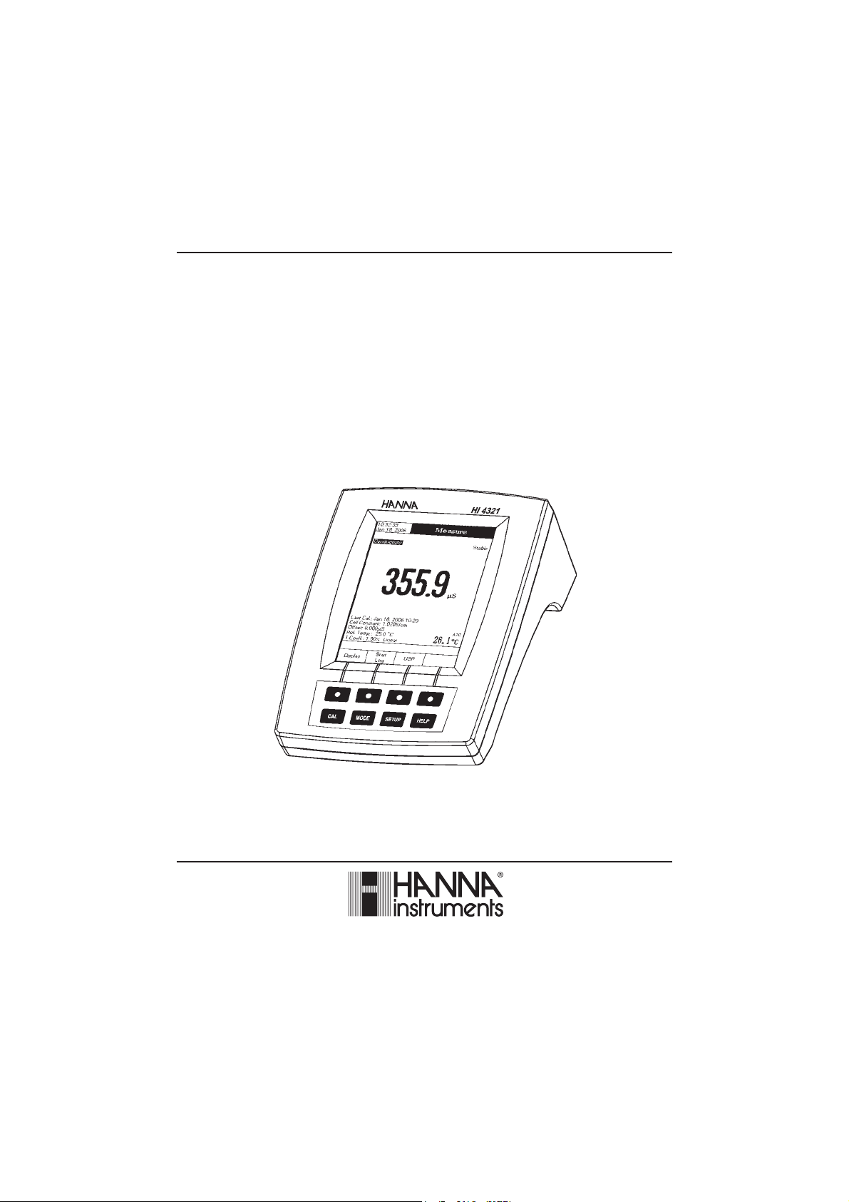
HI 4321
Conductivity/Resistivity/TDS/Salinity/
Temperature
Bench Meter
www.hannainst.com
1
Page 2

Dear Customer,
Thank you for choosing a Hanna Instruments product. This manual will provide you with the necessary
information for correct use of the instrument.
Please read this instruction manual carefully before using the instrument.
If you need additional technical information, do not hesitate to e-mail us at tech@hannainst.com or see the
back side of this manual for our worldwide sales and technical service contacts.
These instruments are in compliance with
HI 4321 is warranted for two years against defects in workmanship and materials when used for their
intended purpose and maintained according to instructions. The probe is guaranteed for six months. This
warranty is limited to repair or replacement free of charge.
Damage due to accidents, misuse, tampering or lack of prescribed maintenance is not covered.
If service is required, contact the dealer from whom you purchased the instrument. If under warranty, report
the model number, date of purchase, serial number and the nature of the failure. If the repair is not covered
by the warranty, you will be notified of the charges incurred. If the instrument is to be returned to Hanna
Instruments, first obtain a Returned Goods Authorization number from the Technical Service Department and
then send it with shipping costs prepaid. When shipping any instrument, make sure it is properly packed for
complete protection.
To validate your warranty, fill out and return the enclosed warranty card within 14 days from the date of
purchase.
directives.
WARRANTYWARRANTY
WARRANTY
WARRANTYWARRANTY
2
Page 3

TABLE OF CONTENTSTABLE OF CONTENTS
TABLE OF CONTENTS
TABLE OF CONTENTSTABLE OF CONTENTS
WARRANTY ...................................................................................................................................... 2
PRELIMINARY EXAMINATION .............................................................................................................. 4
GENERAL DESCRIPTION ...................................................................................................................... 4
FUNCTIONAL DESCRIPTION ................................................................................................................ 5
SPECIFICATIONS ................................................................................................................................ 7
OPERATIONAL GUIDE ....................................................................................................................... 9
DISPLAYING MODES ......................................................................................................................... 10
SYSTEM SETUP ............................................................................................................................... 13
CONDUCTIVITY SETUP ......................................................................................................................... 19
RESISTIVITY SETUP ............................................................................................................................. 34
TDS SETUP .............................................................................................................. 36
SALINITY SETUP .............................................................................................................. 38
CONDUCTIVITY CALIBRATION.................................................................................. 40
CONDUCTIVITY MEASUREMENT.................................................................................. 42
RESISTIVITY MEASUREMENT .................................................................................. 45
TDS MEASUREMENT ............................................................................................... 46
SALINITY CALIBRATION .................................................................................. 47
SALINITY MEASUREMENT .................................................................................. 48
TEMPERATURE CALIBRATION .................................................................................. 50
LOGGING ....................................................................................................................................... 51
PC INTERFACE .................................................................................................................................... 56
PROBE CONDITIONING & MAINTENANCE ..................................................................................... 56
TROUBLESHOOTING GUIDE .............................................................................................................. 57
ACCESSORIES .................................................................................................................................. 58
3
Page 4

PRELIMINARY EXAMINATIONPRELIMINARY EXAMINATION
PRELIMINARY EXAMINATION
PRELIMINARY EXAMINATIONPRELIMINARY EXAMINATION
Remove the instrument from the packing material and examine it carefully to make sure that no damage has
occurred during shipping. If there is any damage, notify your dealer or the nearest Hanna Service Center.
The meter is supplied complete with:
• HI 76312 Four-ring Conductivity Probe with built-in temperature sensor and ID
• HI 76404N Electrode Holder
• 12Vdc Power Adapter
• Instruction Manual
HI 4321 is supplied with 12 Vdc/230 Vac adapter.
HI 4321-01 is supplied with 12 Vdc/115 Vac adapter.
Note: Save all packing material until you are sure that the instrument works properly. Any defective item
must be returned in the original packing with the supplied accessories.
GENERAL DESCRIPTIONGENERAL DESCRIPTION
GENERAL DESCRIPTION
GENERAL DESCRIPTIONGENERAL DESCRIPTION
HI 4321 is a professional bench meter with color graphic LCD for conductivity, resistivity, TDS, salinity and
temperature measurements.
The display viewing modes are: Basic information only, GLP information, Graph and Log History mode.
The main features of the instruments are:
• One input channel;
• Five measurement parameters: conductivity, resistivity, TDS, salinity and temperature;
• Pure water checking using the USP <645> standard;
• Automatic or custom standard conductivity calibration in up to four points, probe offset calibration;
• One fixed point salinity calibration (Percent Scale only);
• AutoHold feature to freeze the stable reading on the LCD;
• Two selectable alarm limits (for conductivity, resistivity, TDS, salinity);
• Three selectable logging modes: Automatic logging, Log on demand (manual logging) and AutoHold logging
mode;
• Up to 100 logging lots for automatic or manual modes and up to 200 USP reports;
• Selectable area and settable sampling period feature for automatic logging;
• GLP feature;
• Online and offline graph;
• User-friendly interface on large color graphic LCD (240x320 pixels);
• Opto-isolated PC interface via RS232 respectively USB.
4
Page 5
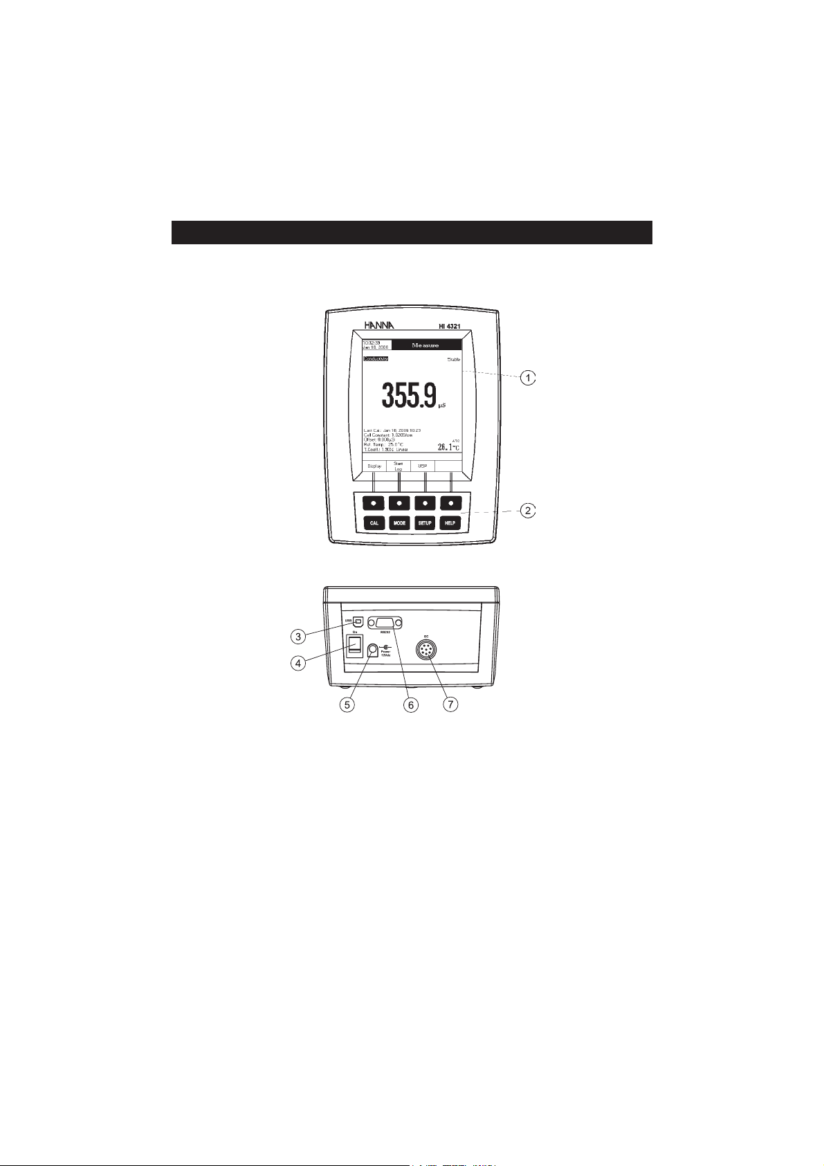
HI 4321 DESCRIPTION
FRONT PANEL
REAR PANEL
FUNCTIONAL DESCRIPTIONFUNCTIONAL DESCRIPTION
FUNCTIONAL DESCRIPTION
FUNCTIONAL DESCRIPTIONFUNCTIONAL DESCRIPTION
1) Liquid Crystal Display (LCD)
2) Main Keyboard
3) USB connector
4) ON/OFF switch
5) Power adapter socket
6) RS232 serial communication connector
7) Conductivity probe input
5
Page 6
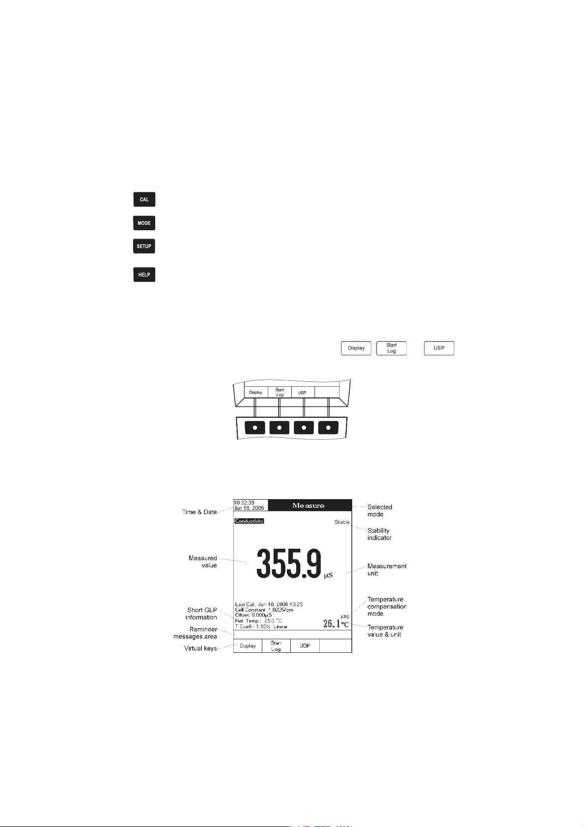
KEYBOARD DESCRIPTION
FUNCTION KEYS
To enter / exit calibration mode.
To select the desired measurement mode: Conductivity, Resistivity, TDS, Salinity.
To enter Setup (System Setup, Conductivity Setup, Resistivity Setup , TDS Setup or Salinity
Setup) and to access Log Recall function.
To obtain general informations about the selected option / operation.
VIRTUAL KEYS
The upper row keys are assigned to the virtual keys placed on the bottom of the LCD, which allow you to
,
perform the displayed function, depending on the current menu (e.g.
Measure
mode).
and in
LCD GENERAL DESCRIPTION
6
Page 7
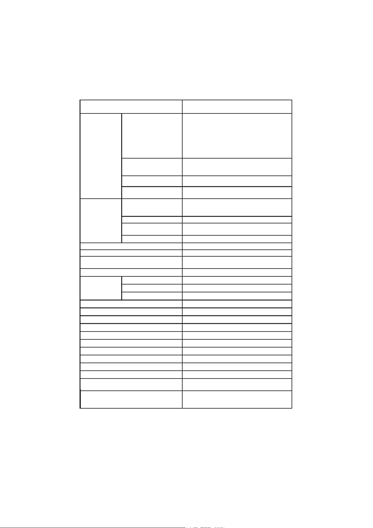
SPECIFICATIONSSPECIFICATIONS
SPECIFICATIONS
SPECIFICATIONSSPECIFICATIONS
1234IH
mc/Sµ999.9ot000.0
egnaR
noituloseR
ycaruccA)mc/Sµ10.0±(gnidaerfo%1±
ytivitcudnoC
ytivitsiseR
SDT
tnatsnoclleC00.002ot0050.0
epytlleCsllec4,2
stniop/epytnoitarbilaC
rednimernoitarbilaCseY
noitasnepmocerutarepmeTdelbasiD/)retawlarutan(raenilnoN/raeniL
tneiciffeocerutarepmeTC°/%00.01ot00.0
erutarepmetecnerefeRC°0.03otC°0.51
seliforP01otpU
tnailpmocPSUseY
egnaR
noituloseR
ycaruccA)mcxmhO1±(gnidaerfo%2±
egnaR
noituloseR
ycaruccA)mpp10.0±(gnidaerfo%1±
mc/Sµ99.99ot00.01
mc/Sµ9.999ot0.001
mc/Sm999.9ot000.1
mc/Sm99.99ot00.01
mc/Sm0.0001ot0.001
mc/Sµ100.0
mc/Sµ10.0
mc/Sµ1.0
mc/Sm100.0
mc/Sm10.0
mc/Sm1.0
dradnatsresU,noitingocerdradnatsotuA
noitarbilactnioPitluM/tnioPelgniS
mcxsmhO9.99ot0.1
mcxsmhO999ot001
mcxsmhOK99.9ot00.1
mcxsmhOK9.99ot0.01
mcxsmhOK999ot001
mcxsmhOM99.9ot00.1
mcxsmhOM0.001ot0.01
mcxsmhO1.0
mcxsmhO1
mcxsmhOK10.0
mcxsmhOK1.0
mcxsmhOK1
mcxsmhOM10.0
mcxsmhOM1.0
mpp999.9ot000.0
mpp99.99ot00.01
mpp9.999ot0.001
tpp999.9ot000.1
tpp99.99ot00.01
tpp0.004ot0.001
mpp100.0
mpp10.0
mpp1.0
tpp100.0
tpp10.0
tpp1.0
)rotcaf00.1htiw(SDTlautca
7
Page 8
1234IH
elacSytinilaSlacitcarP
usp00.24ot00.0
egnaR
ytinilaS
noituloseR
ycaruccAgnidaerfo%1±
noitarbilaC
egnaR
erutarepmeT
draobyeK)syeklautriv4(syek8
PLG
dloH-otuAseY
erutaefgniggoL
DCLslexip023x042DCLcihparGroloC
thgilkcaB)revasthgilkcabelbatteshtiw(seY
stupnINIDnip8
stuptuOBSU,232SR
rewoPretpadacdV21
snoisnemiD)"7.3x1.9x3.6(mm49x132x061
thgieW)bl6.2(gK2.1
seirosseccA
noituloseRK1.0/F°1.0/C°1.0
ycaruccA
noitarbilacresUnoitarbilacstniop3
noitacilppaCPseY
selpmasdroceRtol/sdrocer00001htiwstol001
lavretnigniggoLemitgolxamdnas1neewtebelbatteS
epyTdloHotuA,dnamednogoL,citamotuA
noitazinitalpeRseY
sdradnatsdetnemelpmI3,2,1egatsPSU
noitingocereborPseY
noitulosnoitarbilacCE
retaW
elacSretaWaeSlarutaN
tpp00.08ot00.0
elacStnecreP
%0.004ot0.0
aeSlarutaN/elacSytinilaSlacitcarProf10.0
elacStnecreProf%1.0
tniop1-elacStnecreP
)reffub7307IHhtiw(
C°0.021ot0.02-
F°0.842ot0.4-
K51.393ot51.352
K2.0±/F°4.0±/C°2.0±
)eborptuohtiw(
,tneiciffeoc/.pmet.fer,tnatsnoclleC
tesffoeborp,pmatsemit.lac,stniopnoitarbilac
,mc/Sm00.5,mc/Sµ3141,mc/Sµ0.48
mc/Sm8.111,mc/Sm0.08,mc/Sm88.21
)Sµ005ot0,tsnocllec1.0(eborpllec2
)egnarediwtnatsnocllec0.1(eborpllec4
)gnikcehcegnarwolroftesrotsiser,llecwolf(tikPSU
8
Page 9
OPERATIONAL GUIDEOPERATIONAL GUIDE
OPERATIONAL GUIDE
OPERATIONAL GUIDEOPERATIONAL GUIDE
POWER CONNECTION
Plug the 12 Vdc adapter into the power supply socket.
Note: These instruments use non volatile memory to retain the meter settings, even when unplugged.
PROBE CONNECTION
For conductivity, resistivity, TDS or salinity measurements connect a conductivity probe to the DIN connector
located on the rear panel of the instrument.
INSTRUMENT START UP
• Turn the instrument on from the power switch located on the rear panel of the instrument.
• Please wait until the instrument finishes the initialization process.
Note: It is normal for the loading process to take a few seconds. If the instrument doesn’t display the next
screen, restart the meter using the power switch. If the problem persists, contact your dealer.
9
Page 10
DISPLAYING MODESDISPLAYING MODES
DISPLAYING MODES
DISPLAYING MODESDISPLAYING MODES
For each measurement mode (Conductivity, Resistivity, TDS or Salinity) the following display configurations
are available: Basic, Good Laboratory Practice (GLP), Graph and Log History.
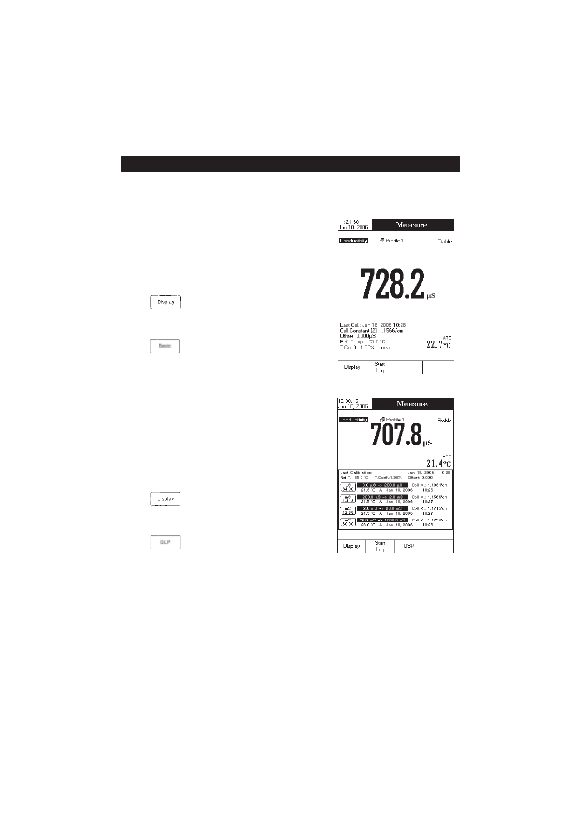
Basic
Accessing this option, the measured value and its units are displayed on the LCD, along with the temperature value, temperature
compensation mode, and minimal GLP data.
To choose the Basic displaying mode:
• Press
Configuration” message will be displayed in the Reminder
messages area.
• Press
tion for the selected measurement mode.
GLP
Accessing this option, a detailed GLP data will be displayed on the
LCD for conductivity and salinity (Percent Scale only)
modes: Last Calibration Date and Time, Cell Constant, Probe
Offset, Reference Temperature, Compensation Coefficient, Temperature Compensation.
To access the GLP displaying mode:
• Press
Configuration” message will be displayed in the Reminder
messages area.
• Press
data.
while in
. The instrument will display the basic informa-
while in
. The instrument will display the detailed GLP
Measure
mode. The “Choose Display
Measure
mode. The “Choose Display
measure
10
Page 11
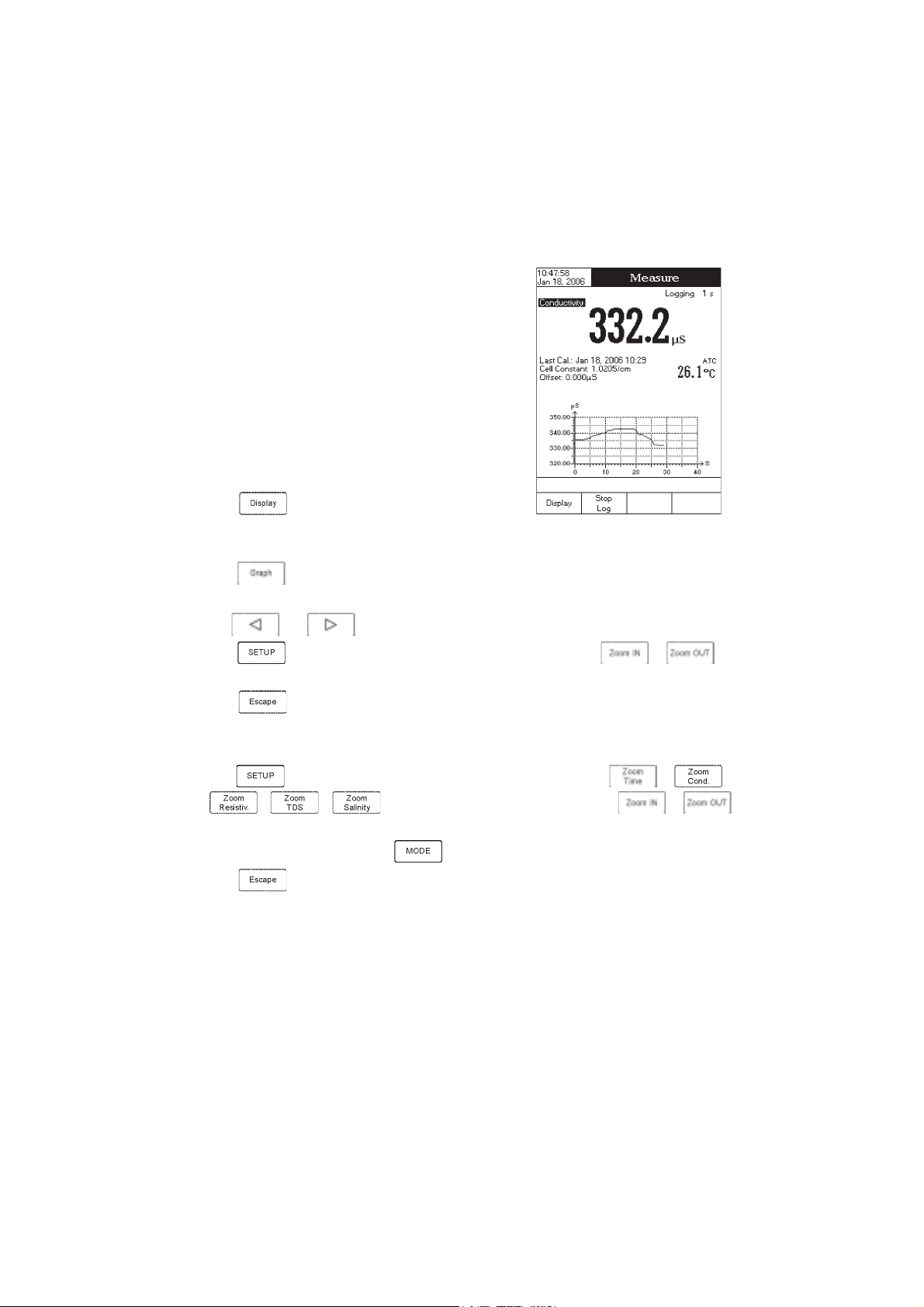
Graph
Accessing this option, the online graph with currently logged
values (Conductivity, Resistivity, TDS or Salinity vs. Seconds)
could be displayed.
If there is no active log, the previously logged data for the
selected parameter will be plotted.
Notes: • If no data were logged, the graph displaying mode
will not be accessible.
• If no automatic log is saved, the offline graph will not
be available.
To access the offline / online graph:
• Press
Configuration” message will be displayed in the Reminder
messages area.
• Press
When the online graph is displayed:
• Use and to move the graph along the horizontal (
• Press to access the zoom menu for the vertical (
vertical axis zooming.
• Press
When the offline graph is displayed:
• Use the arrow keys to move the graph along the horizontal and vertical axes.
• Press
to zoom the selected axis.
Note: While in zoom graph menu the
• Press
while in
.
Measure
mode. The “Choose Display
Time
Parameter
to return to the main menu.
to access the zoom menu for the horizontal and vertical axes. Use or /
/ / to switch between the active zooming axes. Press or
key is not accessible.
to return to the main menu.
) axis. Use or for
) axis.
11
Page 12
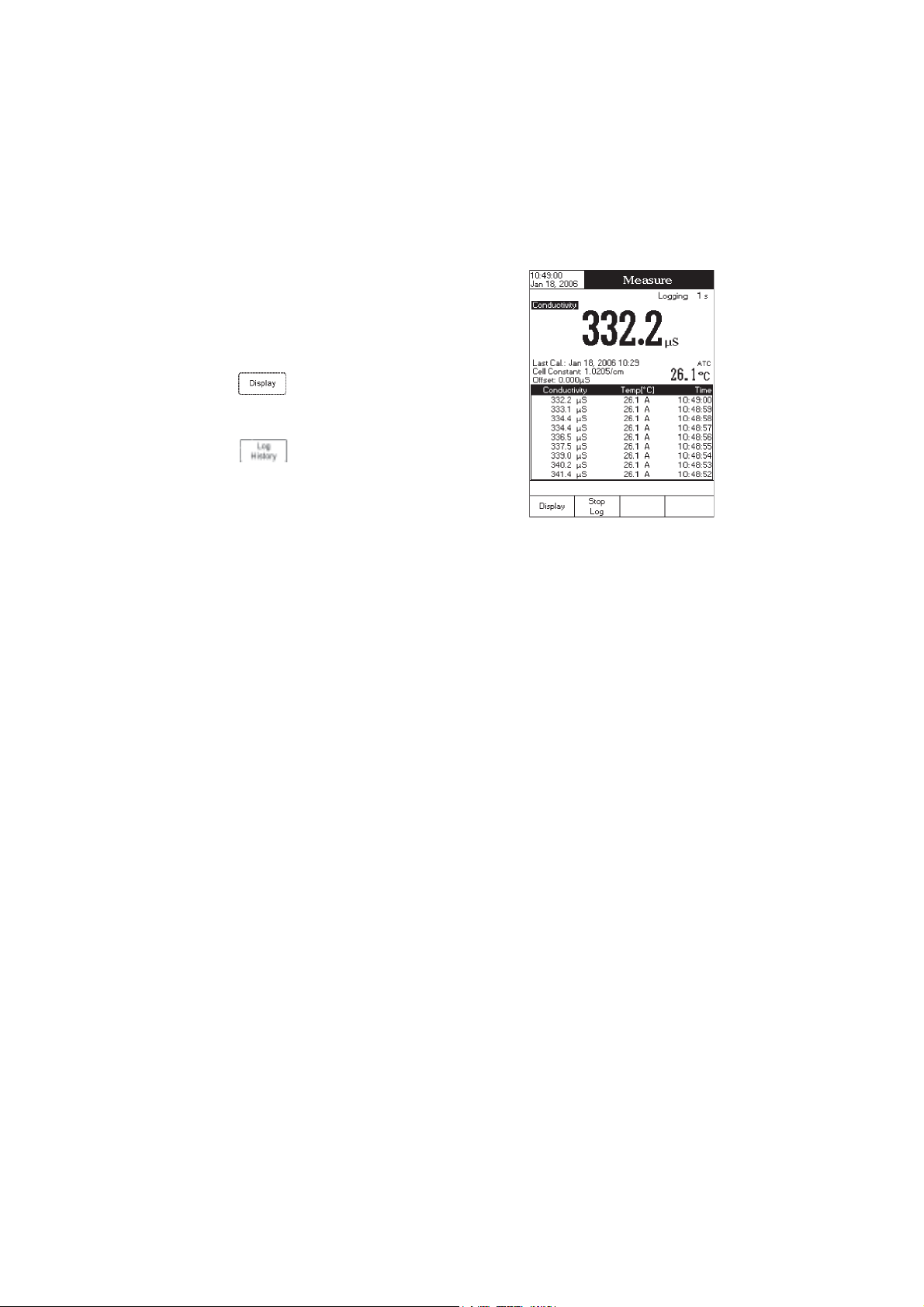
Log History
Accessing this option, last logged records will be displayed on the LCD.
The log history list also contains the appropriate conductivity /
resistivity / TDS / salinity values, the logged temperature, the
temperature source, as well as the records time stamp.
To access the Log History displaying mode:
• Press
Configuration” message will be displayed in the Reminder
messages area.
• Press
regarding the selected measure mode.
Notes: • When an alarm condition is active, the logged records will have an exclamation mark (!).
• When a meter is in auto-hold, the logged records will have an “H” symbol.
• If another measure mode is selected, the Log History will be cleared.
• If the temperature unit is changed, all logged temperature values will be automatically displayed
while in
in the new temperature unit.
Measure
mode. The “Choose Display
. The instrument will display the log history
12
Page 13
SYSTEM SETUPSYSTEM SETUP
SYSTEM SETUP
SYSTEM SETUPSYSTEM SETUP
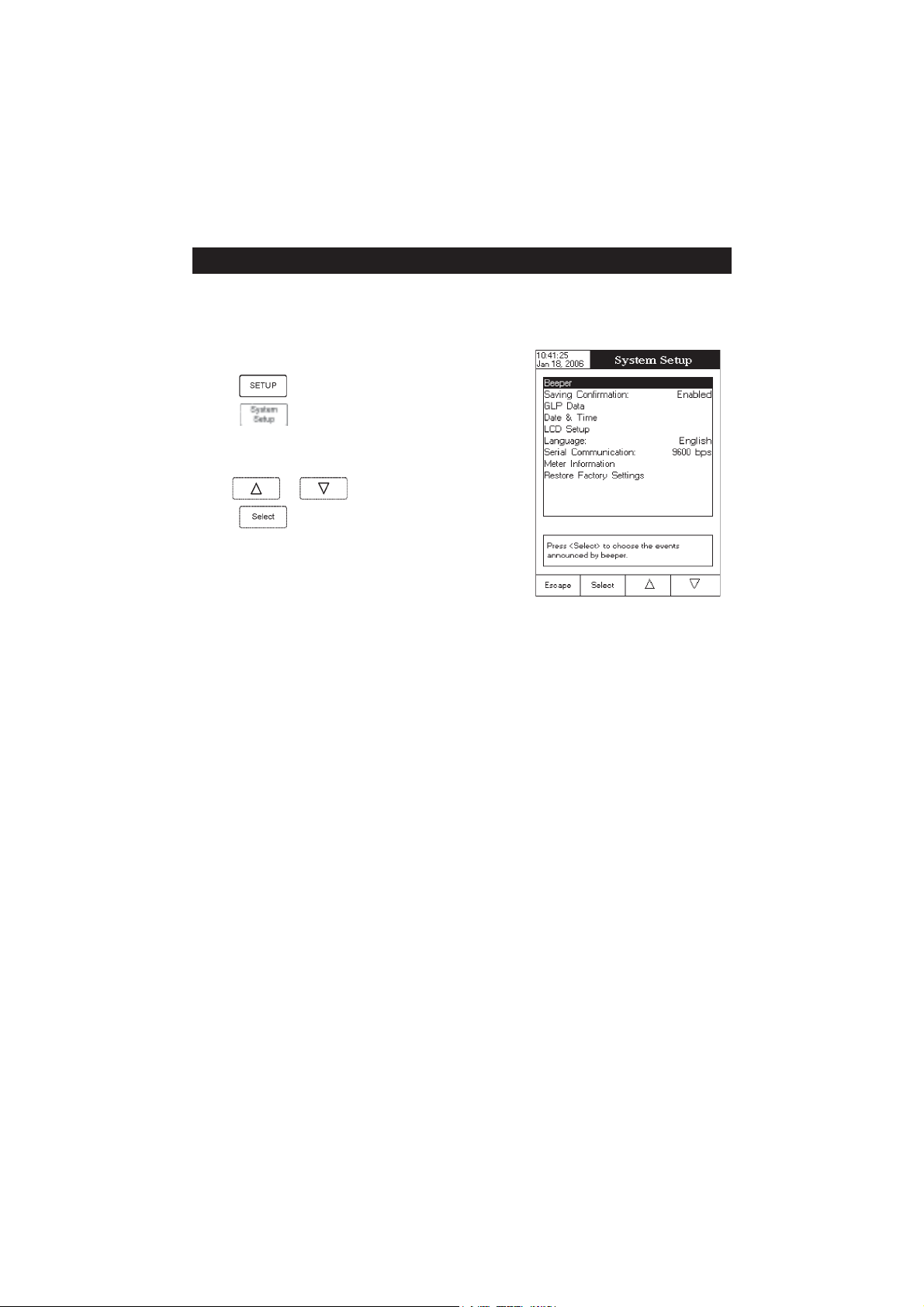
The System Setup menu allows the user to customize the user interface, consult the meter information, set the
external serial communication interface and to restore the manufacturer settings.
Accessing System Setup
• Press
while in
Measure
mode.
• Press
on the LCD.
To access a System Setup option:
• Use
• Press
The following is a detailed description of the System Setup option screen.
Beeper
This option allows the user to enable or disable the beeper. When the beeper is enabled, a specific beep will
be heard when the reading becomes stable, when an alarm condition is reached,
a wrong key is pressed.
. The system setup options will be displayed
or to highlight the desired option.
to access the selected option.
when pressing a key or if
Stability Indicator
When the reading becomes stable, the instrument delivers a medium beep only if this option is activated, along
with the “Stable” indicator on the LCD.
Alarm
If this option is activated, a continuous double beep will be heard each time the set limits in
exceeded, along with the “Alarm” indicator on the LCD.
Key Pressed
If this option is activated, a short beep will be heard each time a valid key is pressed.
Wrong Key
If this option is activated, a long beep will be heard when an incorrect key is pressed.
13
Measure
mode are
Page 14
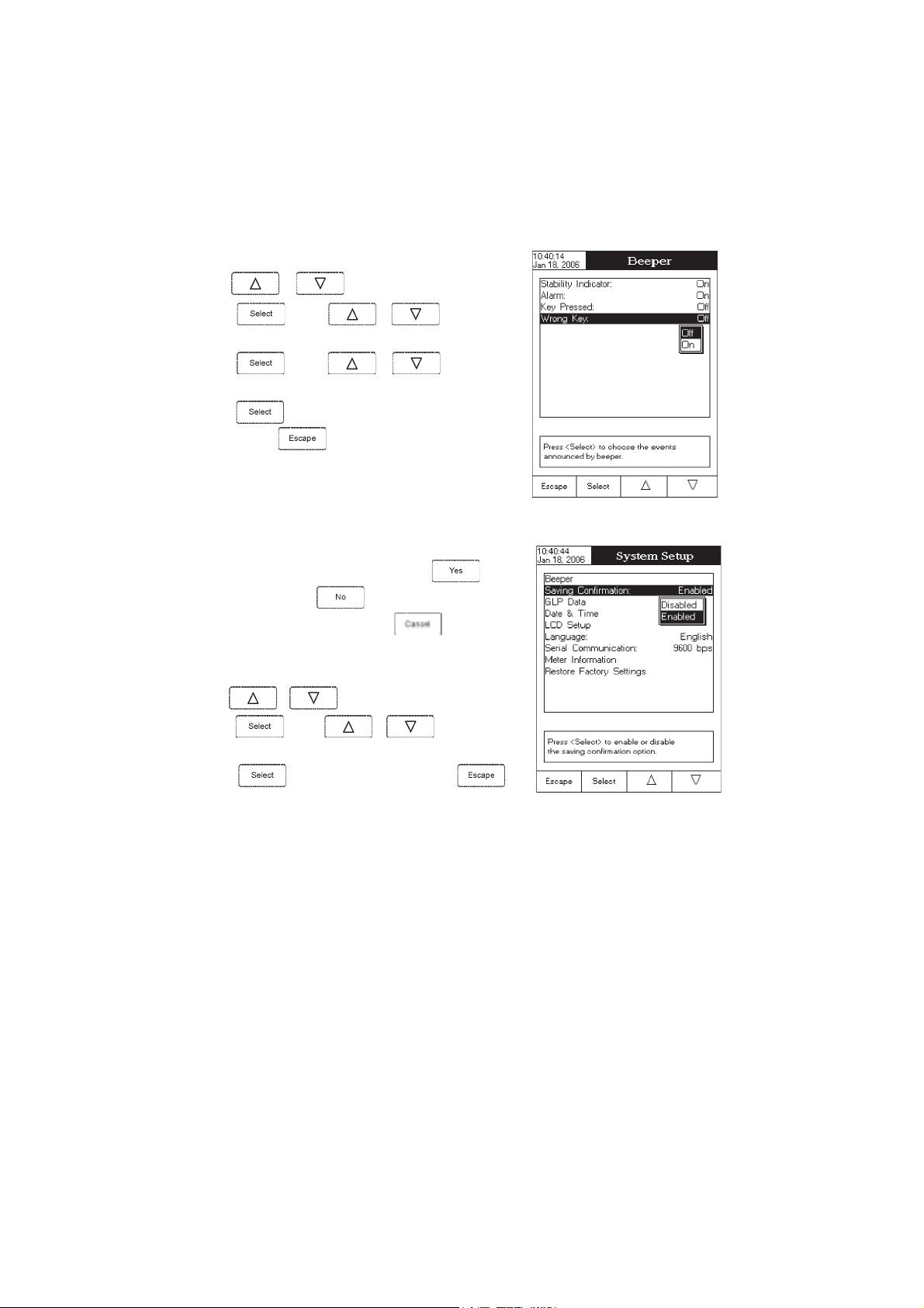
To set the Beeper:
• Use
or to select the
Beeper
option.
• Press
desired beeper associated event you want to modify.
• Press
beeper status option.
• Press
menu or press
Saving Confirmation
When enabling this option, a prompt will appear on the LCD alerting
the user to save the modified values by pressing
without saving by pressing
and return to the editing mode by pressing
modified values will be saved automatically.
To enabled /disabled the saving confirmation:
• Use
• Press and use or to choose enabled
/ disabled.
• Press
cancel operation.
and use or to highlight the
and use or to highlight the
to confirm your selection and return to the
to return without changing.
or canceling the saving operation
or to select the
to confirm your selection or press
Saving Confirmation
Beeper
, exiting
. If disabled, the
option.
to
GLP Data
This option allows the user to set general information which will appear in the log reports. The edited text can have
max 10 characters.
Operator ID
Instrument ID
Company Name
Additional Info 1 & Additional Info 2
– edit the operator’s name.
– edit an identification name / number for the instrument.
– edit the company name.
– for general purpose notations.
14
Page 15
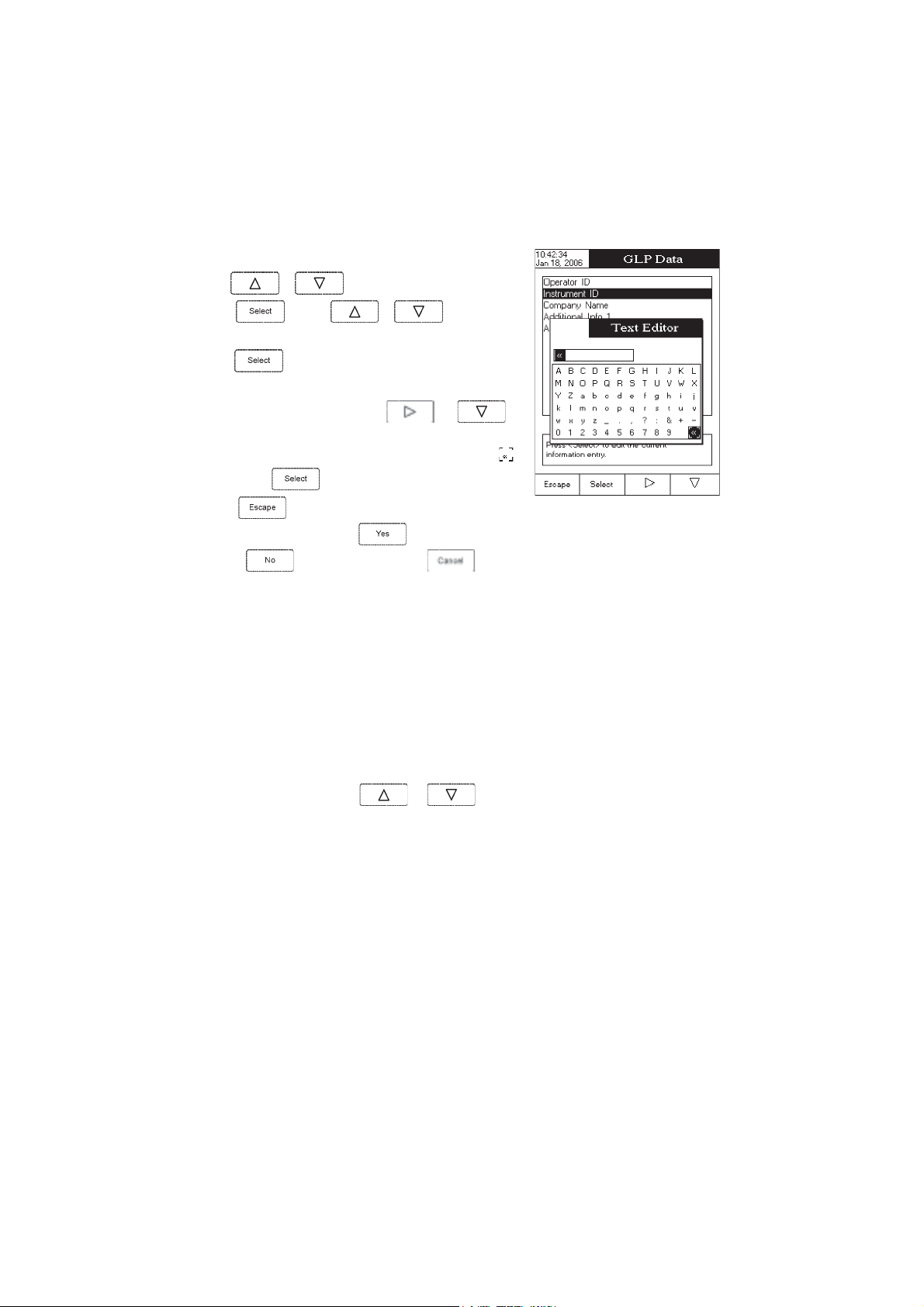
To set the GLP data:
• Use
or to select the
GLP Data
option.
• Press
desired option.
• Press to edit the desired information. The Text Editor menu
will be displayed on the LCD.
• Enter the desired information by using
highlight the desired character. It is also possible to delete the last
character by positioning the cursor on the Backspace character (
and pressing
• Press
Confirmation
option,
options are saved automatically.
Date & Time
This option allows the user to set the current date & time and the format in which they appear. These parameters
will be displayed on the
Set Date and Time
This option allows you to set the current date (year / month / day) and time (hour / minute / second).
Notes: • Only years starting with 2000 are accepted.
• The time is set using the selected time format. For 12 Hour time format only, the AM / PM can
and use or to highlight the
and to
)
.
to return to the
is enabled, press to accept the modified
to escape without saving or to return to the editing mode. Otherwise, the modified
Measure
also be selected with
GLP Data
menu. If the
screens and also when storing measured data.
or .
Saving
Set Time Format
This option allows you to choose between 12 Hour (AM / PM) time format and 24 Hour time format from the
displayed pop-up box.
Set Date Format
This option allows you to choose the desired date format from the available formats: DD/MM/YYYY; MM/DD/YYYY;
YYYY/MM/DD; Mon DD, YYYY; DD-MM-YYYY and YYYY-Mon-DD.
15
Page 16
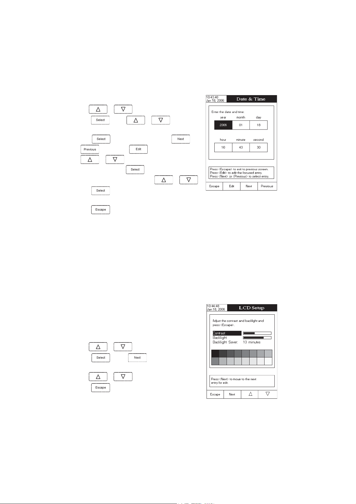
To set the Date & Time:
• Use
or to select the
Date & Time
option.
• Press
desired option you want to modify.
• Press to confirm your selection. Use and
other two options press
select one of the displayed formats with
• Press to confirm your selection and return to the
& Time
• Press
Note: If the time is changed with more than one hour before last measure parameters user calibration, a pop-up
warning will appear on the LCD, notifying the user that a date/time conflict has occured and some timedependent features could work improperly (e.g.
LCD Setup
This option allows the user to set the
parameter can be adjusted within 7 steps, while the
be set from 1 to 60 minutes or it can be disabled (OFF). All the changes are visible on the LCD for each parameter.
and use or to highlight the
and then use to modify the value with
or (for
options.
to return to the previous mode.
Set Date and Time
to confirm your selection and
option). For the
or .
GLP, Log
Contrast
, the
Backlight
Backlight
Date
).
of the LCD and the
parameter within 4 steps. The
Backlight Saver
. The
Contrast
Backlight Saver
can
Note: If the instrument backlight is turned off after the set period of
time, press any key to turn it back on.
To set the LCD:
• Use or to select the
• Press
parameter;
• Use
• Press return to the
and use key to highlight the desired
or to adjust the selected parameter;
System Setup
LCD Setup
option;
menu with saving.
16
Page 17
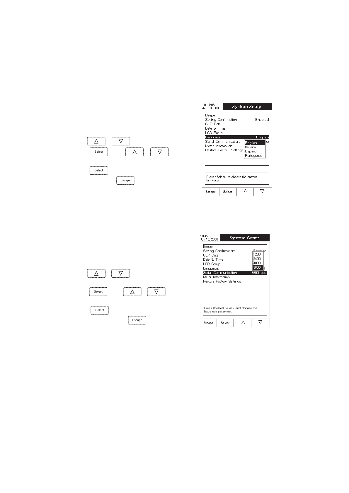
Language
This option allows the user to choose the desired language for the user
interface.
To select the Language:
• Use
• Press and use or to highlight the
desired language.
• Press
or to select the Language option.
to confirm your selection and return to the
System
menu or press
Setup
without changing.
Serial Communication
This option allows the user to set the desired speed for the serial
communication (baud rate) between the instrument and PC from
1200, 2400, 4800 or 9600
To set the serial communication:
• Use
option.
• Press
desired baud rate.
• Press
System Setup
Note: The meter and the PC application must have the same baud rate.
or to select the
and use or to highlight the
to confirm your selection and return to the
menu or press
to return to the
.
System Setup
Serial Communication
to return without changing.
menu
17
Page 18
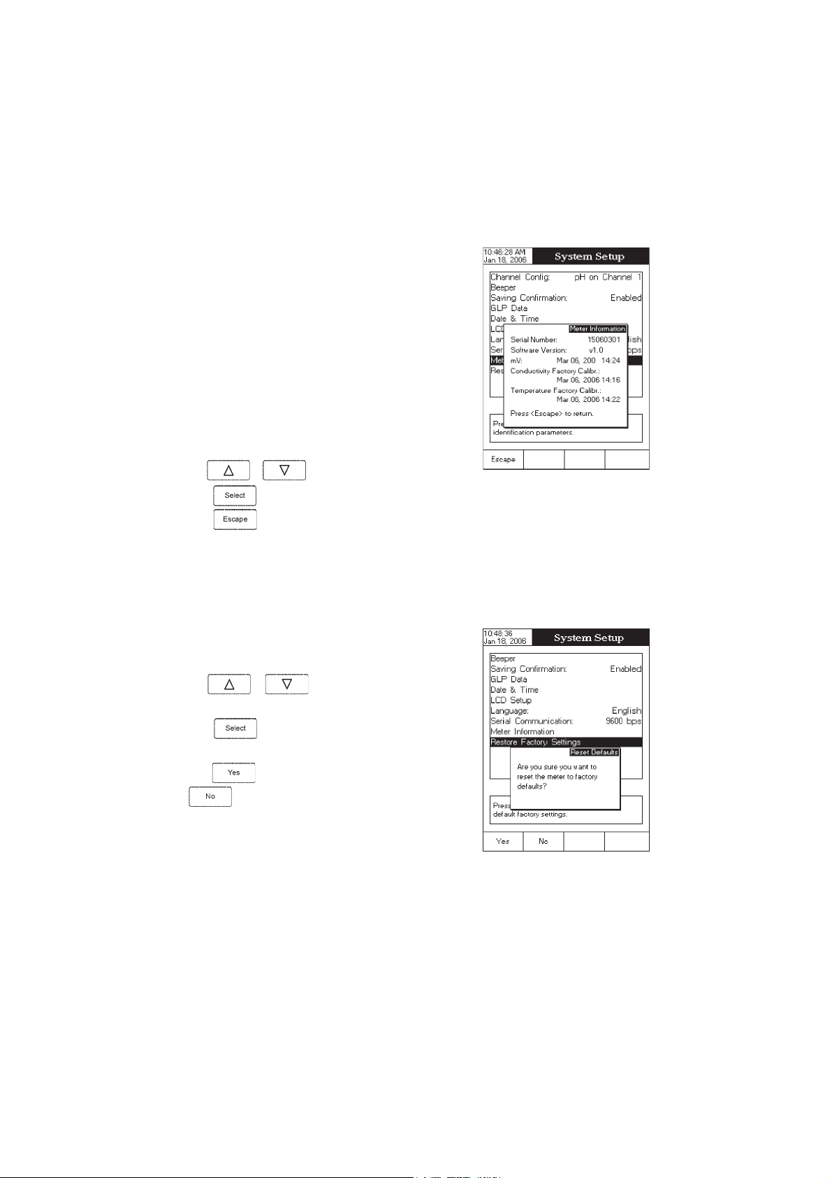
Meter Information
This option provides general information about the instrument serial
number (each instrument has an unique identification serial number),
the software version and the factory calibration date and time (for
conductivity and temperature).
Note: All the instruments are factory calibrated for conductivity and
temperature. After one year from last factory calibration, the
warning will appear at meter startup to inform the user that
a new factory calibration is required.
To view the meter information:
• Use
or to select the
Meter Information
option.
• Press
press
Restore Factory Settings
This option allows the user to reset the instrument to the default
factory settings.
To restore the factory settings:
• Use
option.
• Press
displayed, asking for confirmation.
• Press
to confirm and to view the meter information or
to return to the
or to select the
to confirm your selection. A pop-up box will be
to confirm and return to the
to return without restoring defaults.
System Setup
Restore Factory Settings
System Setup
menu.
or press
18
Page 19

ConductivityConductivity
Conductivity
ConductivityConductivity
The Conductivity Setup menu allows the user to set the parameters related to the conductivity measurement.
Accessing Conductivity Setup
• Press
select the
• Press
menu.
To access a conductivity setup options:
• Use
while in
Conductivity
and then to access
or to highlight the desired option.
Measure
mode and then to
measure mode.
Conductivity Setup
SETUP SETUP
SETUP
SETUP SETUP
• Press
setup.
The following is a detailed description of the
option screens.
Profile
Choosing this option the measuring and the calibration mode can be customized. Up to 10 profiles can be
defined by the user.
The available options are:
Save Current Profile:
Load Profile:
Delete Profile:
to access the selected option or to exit
Conductivity Setup
save the current profile.
load from available profiles.
delete a profile.
19
Page 20

Save Current Profile
To save the current profile:
• Use
or to select the
Profile
option.
• Press
text editor box will be displayed on the LCD.
• Enter the desired profile name by using
highlight the desired character and then press
to the text bar. It is also possible to delete the last character by
positioning the cursor on the Backspace character (
• Press
Note: The saved profile will automatically become the current profile.
and then select
.
to return to the Profile options.
Save Current Profile
and to
) and pressing
option. The
to add it
Load Profile
To load the user customized profile:
• Use
• Press
Load Profile
• Press
displayed on the screen.
• Use
or to select the
option.
or to select the desired profile and press
and use or to highlight the
.
A list with all customised profiles will be
Profile
option.
to
confirm or
to exit without selecting.
20
Page 21

Delete Profile
To delete one of the existing profiles:
• Use
• Press
Delete Profile
• Press
the screen.
• Use
or to select the
and use or to highlight the
option.
.
A list with all customised profiles will appear on
or to select the desired profile and press
.
Profile
option.
• Press
Reading Mode
This option allows the user to select between
Direct/USP
To set the reading mode:
• Use
• Press and use or to highlight the
desired option.
• Press
cancel operation.
to return to the previous menu.
Direct, Direct/AutoHold,
conductivity reading modes.
or to select the
to confirm your selection or press to
Reading Mode
option.
21
Page 22

Temperature
From the
source and units, as well as the temperature compensation mode,
reference temperature and compensation coefficient.
To access a
• Use
• Press
Temperature Source
To set the
• Use
• Press
• Press
cancel operation.
Temperature
Temperature
option from the
temperature source:
or to highlight the
option.
Automatic
or
Manual
menu the user can choose the temperature
option:
or to highlight the
Conductivity Setup
to access the
menu.
Temperature
Temperature
option.
Temperature Source
and then use or to select
temperature source.
to confirm your selection or press to
22
Page 23

Temperature Compensation
The user can choose from the following options:
Linear -
the meter will compensate automatically the conductivity using the following formula:
where:
C
- conductivity at reference temperature
ref
- measured conductivity (uncompensated)
C
i
- compensation coefficient
T - temperature
ref - reference temperature
Non-Linear -
compensation table on the next page.
Disabled -
To set the
temperature compensation mode:
• Use
Compensation
• Press
or to highlight the
option.
and then use or to select
Linear, Non-Linear
• Press
to confirm your selection or press to cancel
operation.
recommended for measuring the conductivity of the natural water in accordance with the
the meter will display the conductivity with no temperature compensation.
Temperature
or
Disabled
option.
23
Page 24

Table for non-linear temperature compensation:
0123456789
0819.1219.1509.1998.1398.1788.1188.1578.1968.1368.1
1758.1158.1548.1048.1438.1928.1228.1718.1118.1508.1
2008.1497.1887.1387.1777.1277.1667.1167.1657.1057.1
3547.1047.1437.1927.1427.1917.1317.1807.1307.1896.1
4396.1886.1386.1876.1376.1866.1366.1856.1356.1846.1
5346.1836.1436.1926.1426.1916.1516.1016.1506.1106.1
6695.1195.1785.1285.1875.1375.1965.1465.1065.1555.1
7155.1745.1245.1835.1435.1925.1525.1125.1615.1215.1
8805.1405.1005.1694.1194.1784.1384.1974.1574.1174.1
9764.1364.1954.1554.1154.1744.1344.1934.1634.1234.1
01824.1424.1024.1614.1314.1904.1504.1104.1893.1493.1
11093.1783.1383.1973.1673.1273.1963.1563.1263.1853.1
21453.1153.1743.1443.1143.1733.1433.1033.1723.1323.1
31023.1713.1313.1013.1703.1303.1003.1792.1492.1092.1
41782.1482.1182.1872.1472.1172.1862.1562.1262.1952.1
51652.1352.1942.1642.1342.1042.1732.1432.1132.1822.1
61522.1222.1912.1612.1412.1112.1802.1502.1202.1991.1
71691.1391.1191.1881.1581.1281.1971.1771.1471.1171.1
81861.1661.1361.1061.1751.1551.1251.1941.1741.1441.1
91141.1931.1631.1431.1131.1821.1621.1321.1121.1811.1
02611.1311.1111.1801.1501.1301.1101.1890.1690.1390.1
12190.1880.1680.1380.1180.1970.1670.1470.1170.1960.1
22760.1460.1260.1060.1750.1550.1350.1150.1840.1640.1
32440.1140.1930.1730.1530.1230.1030.1820.1620.1420.1
42120.1910.1710.1510.1310.1110.1800.1600.1400.1200.1
52000.1899.0699.0499.0299.0099.0789.0589.0389.0189.0
62979.0779.0579.0379.0179.0969.0769.0569.0369.0169.0
72959.0759.0559.0359.0259.0059.0849.0649.0449.0249.0
82049.0839.0639.0439.0339.0139.0929.0729.0529.0329.0
92129.0029.0819.0619.0419.0219.0119.0909.0709.0509.0
03309.0209.0009.0898.0698.0598.0398.0198.0988.0888.0
13688.0488.0388.0188.0978.0778.0678.0478.0278.0178.0
23968.0768.0668.0468.0368.0168.0958.0858.0658.0458.0
33358.0158.0058.0848.0648.0548.0348.0248.0048.0938.0
43738.0538.0438.0238.0138.0928.0828.0628.0528.0328.0
53228.0028.0918.0718.0618.0418.0318.0118.0018.0808.0
24
Page 25

Temperature Unit
The user can choose from the
units.
To set the temperature unit:
• Use
option.
• Press
or to highlight the
Celsius, Fahrenheit
• Press to confirm your selection or press to
cancel operation.
Celsius, Fahrenheit
or
Kelvin
temperature
Temperature Units
and then use or to select
or
Kelvin
degrees unit
.
Reference Temperature
To set the reference temperature:
• Use
perature
option.
• Press
/ decrease the value.
• Press
(only for linear or non-linear temperature compensation)
or to highlight the
and then use
to save or press
Reference Tem-
or to increase
to cancel operation.
25
Page 26

Compensation Coefficient (only for linear temperature compensation)
To set the compensation coefficient:
• Use
Coefficient
• Press
or to highlight the
option.
and set the desired compensation coefficient
Compensation
using
• Press
cancel operation.
Calibration / Cell Constant
The conductivity probe can be calibrated using the conductivity standards or by entering the cell constant of the
probe by the user.
or to increase / decrease the value.
to save the current value or press
to
Using standard solutions
The meter can be calibrated in a single or multi-points (up to four points), using 6 Hanna standards (84 µS, 1413
µS, 5.0 mS,12.88 mS, 80.0 mS, 111.8 mS) or using the custom standards.
The following options are available for calibration:
Standard Recognition
The user can choose between
standards available) or
used for calibration).
• Use
tion
option.
• Use
Standard
• Press to confirm your selection or press to
cancel operation.
or to highlight the
or to choose from
option
.
Automatic
User Standard
recognition (from 6 Hanna
(when custom standards are
Standard Recogni-
Automatic
or
User
26
Page 27

Calibration Points
The user can choose between
To select the calibration points type:
• Use
option.
• Press
or to choose the desired option
• Press to confirm your selection or press to
cancel operation.
or to highlight the
Single Point
and
Multi Points
Calibration Points
to confirm your selection and then use
.
calibration.
Cell constant manual editing
The conductivity probe can also be calibrated by entering the cell
constant value.
To edit the cell constant value:
• Use
• Press .
or to highlight the
Cell Constant
option.
• Press
auto-recognizable default cell constant.
• Use
• Press to confirm the new value or press to
exit without modifying.
to preset the cell constant value to the probe
or to increase / decrease the value.
27
Page 28

Calibration Reminder
This option allows the user to set the calibration reminder as
Periodic
or
Disabled
.
To set the calibration reminder:
• Use
minder
• Press
or to choose the desired option
• Press to confirm your selection or press to
cancel operation.
or to highlight the
option.
to confirm your selection and then use
.
Daily
Calibration re-
,
Set Reminder Period
Daily
reminder - the user can set the time from the day when the reminder is to appear.
Periodic
reminder - the user can set the time from the last calibration (days, hours and minutes) after which the
reminder appears.
To set the reminder period:
• Use
option.
• Press
previous entry to be edited.
• Press and use or to set the desired
value, then press
or to highlight the
and use / to select next /
to save the modified value.
Set Reminder Period
• Press to return to the previous menu.
28
Page 29
Clear Calibration
Accessing this option, the existent conductivity calibration can be cleared (the probe cell constant will be reset to
default). If the calibration is cleared, another calibration has to be performed.
To clear calibration:
• Use
• Press to clear calibration. A pop-up menu will be displayed asking for confirmation.
or to highlight the
Clear Calibration
option.
• Press
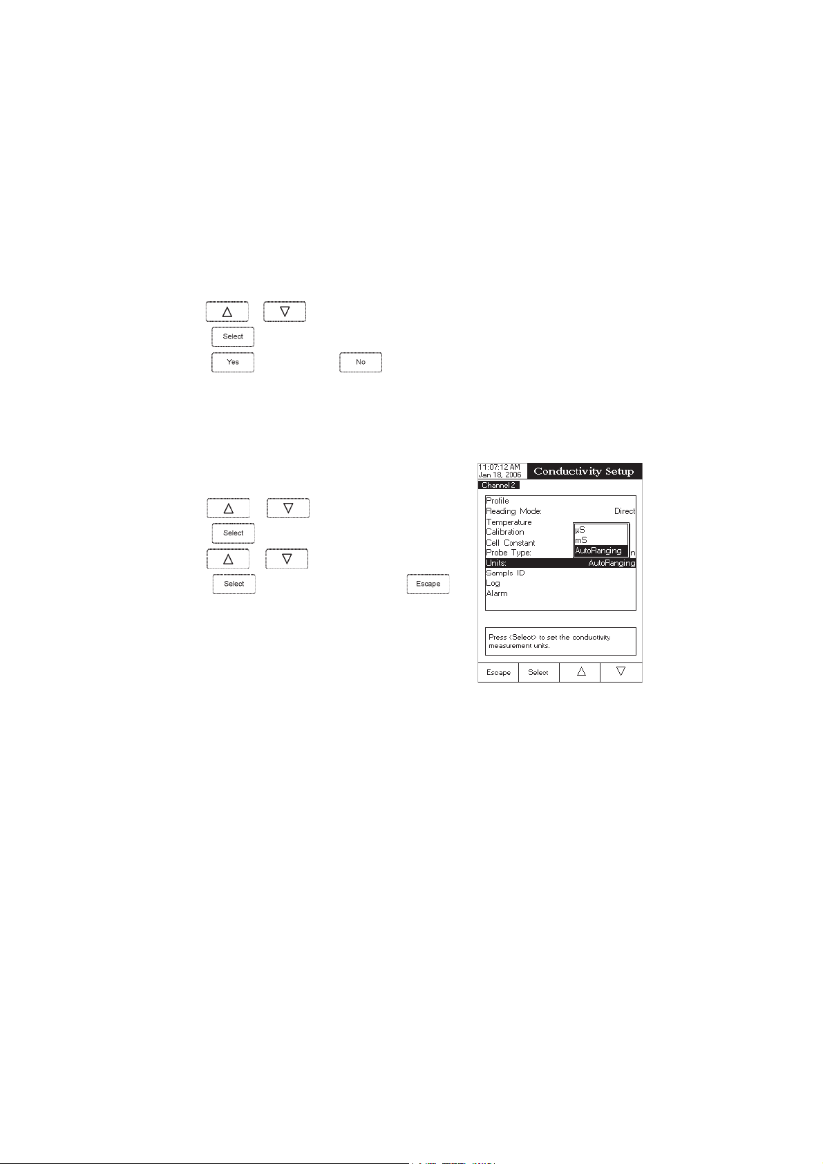
Units
The user can select the desired measurement unit. The available options
are:
µ
S, mS
• Use
• Press
• Use or to select
• Press to confirm your selection or press to
cancel operation.
to confirm or press to escape without saving and return to the Calibration options.
or
AutoRanging
or to highlight the
.
to confirm your selection.
µS, mS
Units
option.
or
AutoRanging.
29
Page 30
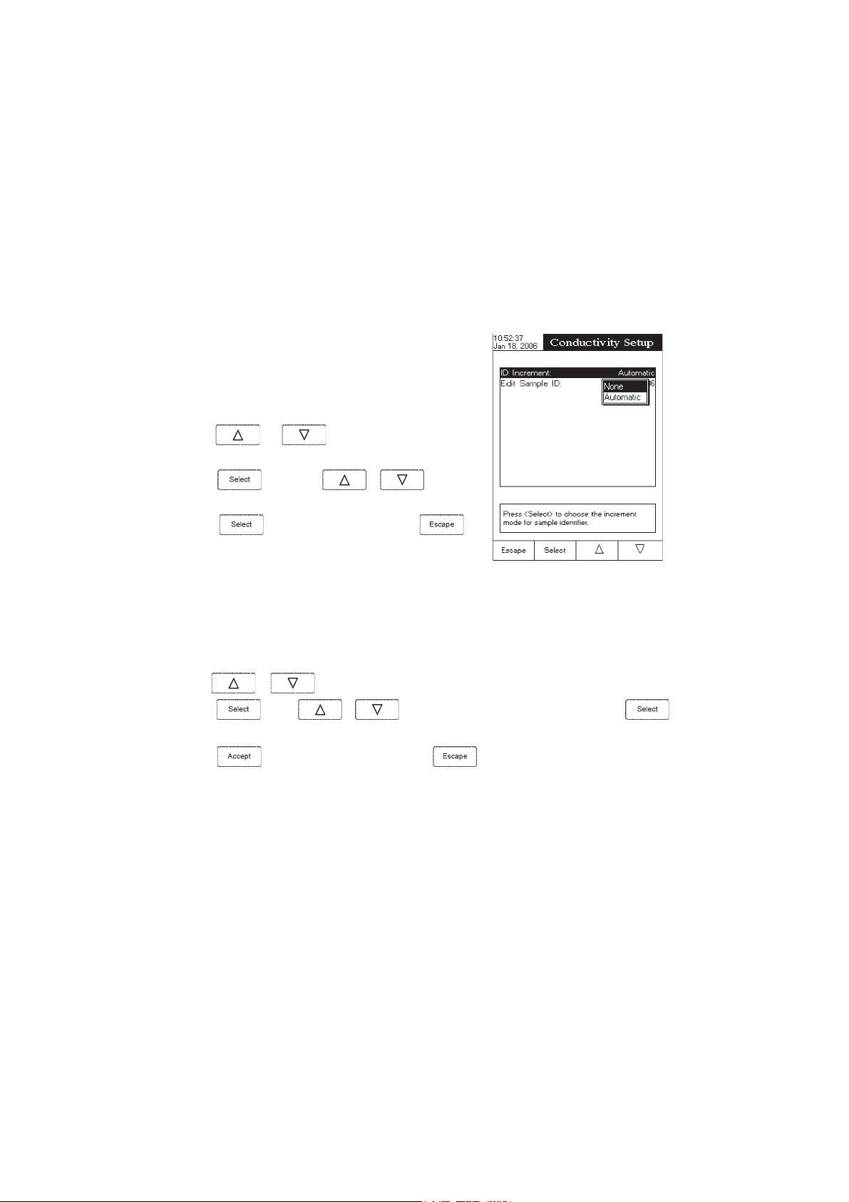
Sample ID
This option allows the user to give to the measured samples an identification number/name. Two
options are available:
ID Increment
and
Edit Sample ID
.
Sample ID
ID Increment
– the sample ID will be edited alphanumerically by the user.
None
Automatic
every new log lot notification.
To select the ID increment mode:
• Use
• Press
• Press
– the sample ID will be automatically incremented at
or to highlight the
option.
and then use or to highlight
the desired option.
to confirm your selection or press
cancel operation.
ID Increment
to
Edit Sample ID
This option allows the user to edit the sample ID (numeric - auto-increment mode, alphanumeric - user editable).
To edit the Sample ID:
• Use
or to select the Sample ID option.
• Press
• Edit numerically / alphanumerically the sample ID.
• Press to save the current sample ID or press
and use or to highlight the
30
Edit Sample ID
to cancel operation.
option and then press .
Page 31

Log
This option allows the user to edit the settings related to the logging feature, as following:
Logging Type
Three logging types are available:
Automatic logging
time intervals (see
Manual logging
AutoHold logging
auto-hold event occured.
To set the sample logging type:
• Use
- the readings are logged automatically at constant
Sampling Period
( log on demand)- the readings are logged each time
is pressed.
- the readings are logged automatically at each
or to highlight the
Automatic, Manual
option).
Logging Type
and
AutoHold.
option.
• Press
Automatic, Manual
• Press
cancel operation.
and use or to choose from
or
Auto Hold
.
to confirm your selection or press to
Logging Data Configuration
This option allows the user to select the parameters that accompany a
logged value:
Operator ID, Company Name, Aditional Info 1
To customise the logging data configuration:
• Use
Configuration
• Press
the parameter by selecting
each option.
• Press
Date/Time, Calibration Data, Sample ID, Instrument ID
and
Aditional Info 2
or to highlight the
option.
and then use or to enable
Yes
or to disable it by selecting
to return to the previous menu.
Logging Data
.
No
for
,
31
Page 32

Sampling Period
This option allows the user to select the desired sampling period for
automatic logging.
To set the sampling period:
• Use
or to highlight the
Sampling Period
option.
• Press
desired option from
• Press
cancel operation.
and use or to select the
1, 2, 5, 10, 30
to confirm your selection or press to
seconds.
New Lot
Accessing this option, the new manually logged readings will be put in a new log lot.
To generate a new lot:
• Use
• Press
• Press
Note: The
or to highlight the
to generate a new manual lot. A pop-up menu will be displayed to ask for confirmation.
to confirm or press to escape without saving and return to the Log options.
New Lot
option is available only for manual logging.
New Lot
option.
32
Page 33

Alarm
This option allows the user to define two alarm limits for the measurements.
Alarm State
The following options are available:
Disabled
Inside Limits
Outside Limits
To set the alarm state:
• Use
– the alarm will be disabled.
– the alarm will notify the user when the measured value is inside the preset limits.
– the alarm will notify the user when the measured value is outside the preset limits.
or to highlight the
Alarm State
option.
• Press
desired option.
• Press to confirm your selection or press
cancel operation.
Alarm Limits
This option allows the user to set the alarm limits for the measured
value.
Note: The alarm high value cannot be lower than the alarm low
value.
To set the alarm limits:
• Highlight the
• Use or to select the low / high alarm limit and
then press
• Use
alarm value.
• Press to return to the
and use or to highlight the
Alarm Limits
or to increase / decrease the selected
option and then press
.
Alarm
.
options.
to
33
Page 34

ResistivityResistivity
Resistivity
ResistivityResistivity
The Resistivity Setup menu allows the user to set the parameters related to the resistivity measurements.
Accessing Resistivity Setup
• Press
select resistivity range.
• Press
menu.
To access a
• Use
while in
and then to access
Resistivity Setup
or to select the desired option.
Measure
mode and then to
option:
SETUP SETUP
SETUP
SETUP SETUP
Resistivity Setup
• Press
The following is a description of the Resistivity Setup option
screens.
Profile - see
Reading Mode
This option allows the user to select between
resistivity reading modes.
To set the
• Use or to select the
• Press
desired option.
• Press
cancel operation.
to confirm your selection.
Conductivity Setup
section.
Direct
Reading Mode:
Reading Mode
and use or to highlight the
to confirm your selection or press to
and
Direct/AutoHold
option.
34
Page 35

Temperature - see
Units
The user can choose between Ohm, KOhm, MOhm, AutoRanging
measuring modes.
To select the units:
• Use or to highlight the
• Press to confirm and then use or
to highlight the desired unit.
• Press
Conductivity Setup
to confirm or press to cancel operation.
section.
Units
option.
Sample ID - see
Log - see
Alarm - see
Conductivity Setup
Conductivity Setup
Conductivity Setup
section.
section.
section.
35
Page 36

TDSTDS
SETUP SETUP
TDS
SETUP
TDSTDS
SETUP SETUP
The TDS Setup menu allows the user to set the parameters related to the TDS measurement.
Accessing TDS Setup
• Press
select TDS range.
• Press and then
To access a TDS Setup option:
• Use
while in
or to highlight the desired option.
Measure
mode and then to
to access TDS Setup menu.
• Press
The following is a description of the TDS Setup option screens.
Profile - see
Reading Mode - see
Temperature - see
Units
This option allows the user to set the TDS measuring range
ppm(mg/L), ppt (g/L), AutoRanging
To select the suitable unit:
• Use
• Press
to highlight the desired range option.
• Press
cancel operation.
to access the selected option.
Conductivity Setup
Conductivity Setup
or to highlight the
to confirm and then use or
to confirm your selection or press to
section.
Resistivity Setup
section.
section.
TDS Units
.
36
Page 37

TDS factor
Using this option the user can set the TDS factor.
• Use
or to highlight the
TDS Factor
option.
• Press
to increase / decrease the value.
• Press
cancel operation.
Sample ID - see
Log -
see
Conductivity Setup
Alarm - see
Conductivity Setup
to confirm your selection and use or
to confirm your selection or press to
Conductivity Setup
section.
section.
section.
37
Page 38

SalinitySalinity
Salinity
SalinitySalinity
The Salinity Setup menu allows the user to set the parameters related to salinity measurement and
calibration.
Accessing Salinity Setup
• Press
select
• Press
menu.
To access an
• Use
• Press to access the selected option.
The following is a description of the
while in
Salinity
range.
Salinity Setup
or to highlight the desired option.
and then
Measure
mode and then to
option:
to access
Salinity Setup
SETUP SETUP
SETUP
SETUP SETUP
Salinity Setup
options.
Profile - see
Reading Mode - see
Temperature
This option allows the user to choose the temperature source and units.
To access temperature options:
• Use
• Press
• Use or to select the desired option and then press to access it.
• Press
Temperature Source, Temperature Unit - see
Conductivity Setup
Resistivity Setup
or to highlight the
to access
to return.
section.
section.
Temperature
Temperature
menu.
Conductivity Setup
38
option.
section.
Page 39

Clear Calibration
Accessing this option, the existent salinity calibration (
To clear calibration:
• Use
• Press to clear calibration. A pop-up menu will be displayed to ask for confirmation.
or to highlight the
Percent Scale
Clear Calibration
only) can be cleared.
option.
• Press
Salinity Scale
The meter uses three salinity scales: Natural Sea Water 1966, Practical Scale 1978, Percent Scale [%].
To select the salinity measurement scale:
• Press
• Press .
• Use
• Press
desired option.
• Press
cancel operation.
Sample ID - see
to confirm or press to cancel operation.
while in salinity measure mode.
or to select the
and use or to highlight the
to confirm your selection or press
Conductivity Setup
section.
Salinity Scale
option.
to
Log - see
Alarm - see
three
Conductivity Setup
section.
Conductivity Setup
section.
39
Page 40

CONDUCTIVITY CALIBRATIONCONDUCTIVITY CALIBRATION
CONDUCTIVITY CALIBRATION
CONDUCTIVITY CALIBRATIONCONDUCTIVITY CALIBRATION
It is recommended to calibrate the instrument frequently, especially if high accuracy is required.
The conductivity range should be recalibrated:
• Whenever the conductivity probe is replaced.
• At least once a week.
• Before USP measurements.
• After testing aggressive chemicals.
• When calibration reminder is activated (“Conductivity Cal Expired”).
• If the readings are far from the calibration point.
Note:TDS and Resistivity readings are automatically derived from the conductivity readings and no specific
calibration is needed.
OFFSET CALIBRATION
The meter allows the user to calibrate the probe for the offset.
• Set the meter for conductivity range;
• Select the automatic standard recognition (see
• Leave the dry probe in the air;
Conductivity Setup
->
Calibration
);
• Enter in calibration mode by pressing
• Wait to stabilize. The 0.000 µS calibration point will appear on the screen;
• Press
• Press to exit calibration mode or continue calibration in the other standard solutions.
Note: The offset calibration can be performed only if it is perfomed first (no other calibration points present).
Clear the old calibration if it is present to calibrate for the offset.
CELL CONSTANT CALIBRATION (in solution)
Single Point Calibration
• Select the single point calibration (see
• Pour a small quantity of the standard solution into a clean beaker. If possible, use plastic beakers to
minimize any EMC interferences.
• For accurate calibration and to minimize cross-contamination, use two beakers for each standard solution
(one for rinsing the probe and another one for calibration).
to finish the probe offset calibration.
;
Conductivity Setup
40
->
Calibration
);
Page 41

• Insert and rinse the probe in the first beaker in order to decontaminate it;
• Insert the probe in the second beaker;
• Tap the probe repeatedly to remove any air bubbles that may be trapped inside the sleeve.
• Enter in calibration mode by pressing
• Wait to stabilize;
• When the automatic standard recognition is selected, the calibration point will be automatically selected
from the Hanna standard list (84 µS, 1413 µS, 5.0 mS,12.88 mS, 80.0 mS, 111.8 mS). The user can
also select the desired standard value by using
• Otherwise (user standard), the pop-up will prompt for entering the custom standard value.
• Press
Note: The calculated cell constant will be used for the wide range.
Multi Point Calibration
• Up to 4 calibration points can be performed in order to
increase the measurement accuracy on the wide range;
• Select the multi point calibration (see
Calibration
• Repeat the steps from the single point calibration for each
calibration point. The meter will calculate a cell constant
corresponding to each calibration point;
• Press
to finish the calibration or to exit calibration.
);
to exit calibration mode.
;
Conductivity Setup
and ;
->
Note: For each range the corresponding cell constant will be displayed.
CELL CONSTANT CALIBRATION (edited by the user)
• A known value of the probe cell constant can be introduced by the user for the wide range (see
Conductivity Setup
Note: When the user cell constant is used the old calibration (in solution) will be cleared.
->
Cell Constant
section)
41
Page 42
CONDUCTIVITY MEASUREMENTCONDUCTIVITY MEASUREMENT
CONDUCTIVITY MEASUREMENT
CONDUCTIVITY MEASUREMENTCONDUCTIVITY MEASUREMENT
Make sure the instrument has been calibrated before taking conductivity measurements.
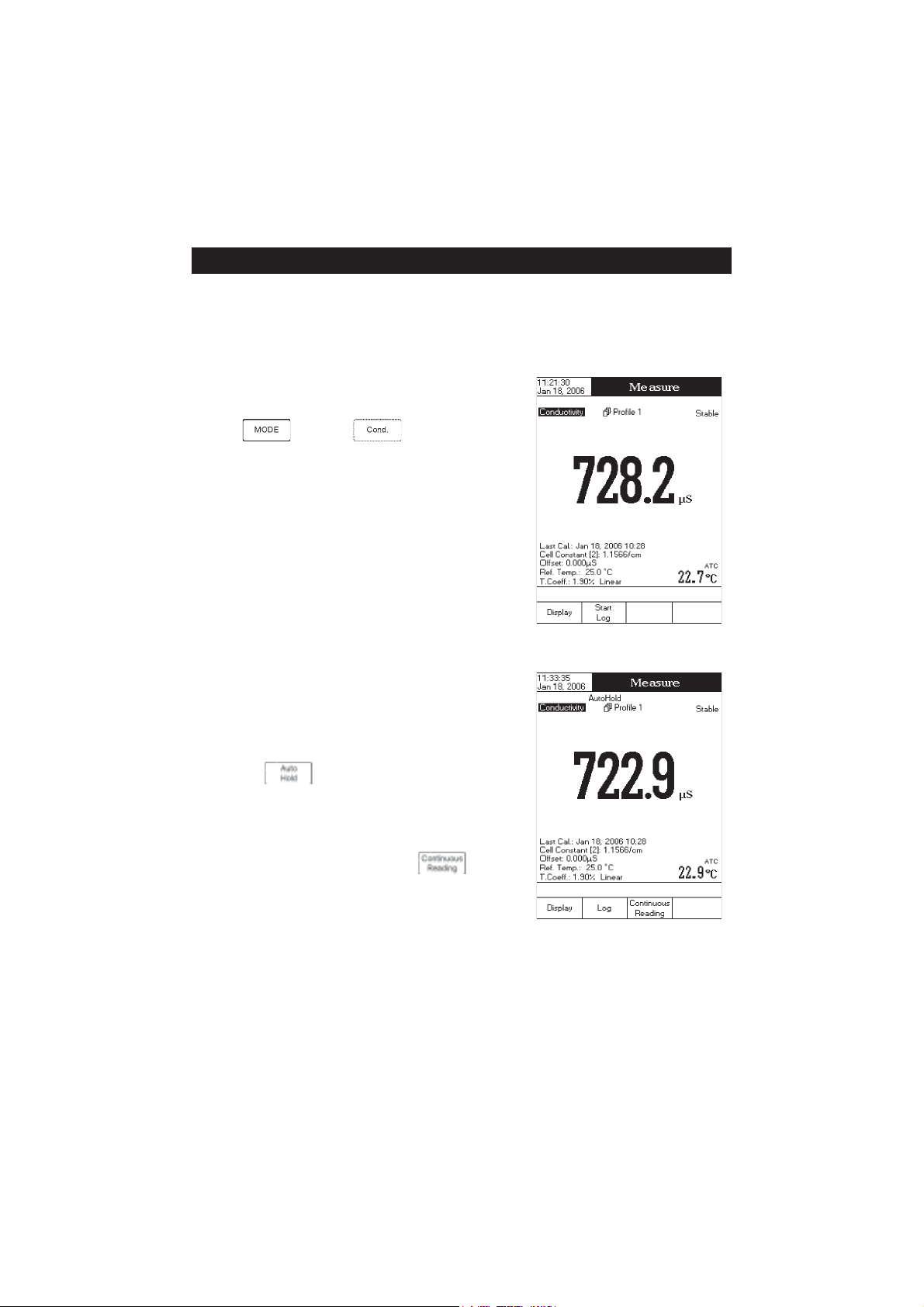
DIRECT MEASUREMENT
To measure the conductivity of a sample using the Direct reading
mode:
• Press
measure mode.
• Select the
• Submerge the conductivity probe and tap
remove any air bubbles that may be trapped inside the sleeve.
Allow time for the reading to stabilize.
• The measured conductivity value will be displayed.
Note: If the reading is out of range, “-----” will be displayed.
DIRECT/AUTOHOLD MEASUREMENT
To measure conductivity of a sample using the Direct/AutoHold
reading mode:
• Select the Direct/AutoHold reading mode (see
Setup
).
• If pressing
ing on the display until the stability criterion is reached. The
conductivity value will be frozen on the display, along with
“AutoHold” indicator.
• To return to normal measure mode press .
and then to select conductivity
Direct
reading mode (see
, the “AutoHold” indicator will start blink-
Conductivity Setup
it repeatedly to
).
Conductivity
42
Page 43

DIRECT/USP MEASUREMENT
In this measure mode the user can check for ultra pure water using the United States Pharmacopeia standard
(USP <645>).
This USP standard consists of three stages (one in-line and two off-line tests) as following:
Stage 1 - this is an in-line test.
Test steps:
• Measure the temperature of the water and the uncompensating conductivity readings. The measurement
may be performed in a suitable container or as in-line measurement.
• The temperature will be round down to the nearest 5 °C and look up the corresponding conductivity value
in the below table.
• If the measured conductivity is lower than the conductivity in the table, then the water meets the USP
requirements.
• Otherwise, proceed to Stage 2 testing.
erutarepmeT
)C°(
06.0551.2
58.0062.2
019.0564.2
510.1075.2
021.1577.2
523.1087.2
034.1587.2
535.1097.2
047.1599.2
548.10011.3
059.1
ytivitcudnoC
)mc/Sµ(
erutarepmeT
)C°(
ytivitcudnoC
)mc/Sµ(
Stage 2 - this is an off-line test.
Test steps:
• Store the water sample in an enclosed clean container that has been rinsed previously with water of the
same quality.
• Adjust the sample’s temperature to 25 °C and agitate the sample to ensure that it has equilibrated with
ambient CO
.
2
• If the measured conductivity is less than 2.1 µS/cm, then the sample has met the USP requirements.
• Otherwise, proceed to Stage 3 testing.
43
Page 44

Stage 3 - this is an off-line test.
Test steps:
• Take the water sample from the previous stage and increase its ionic strength for a pH measurement at
25 °C;
• Record the pH and round it to the nearest 0.1 pH;
• Look up the corresponding conductivity value measured in Stage 2 above;
• If the conductivity is lower than the conductivity from the below table, then the sample has met the USP
requirements. Otherwise, the water didn’t meet the USP requirements.
Hp
0.57.41.64.2
1.51.42.65.2
2.56.33.64.2
3.53.34.63.2
4.50.35.62.2
5.58.26.61.2
6.56.27.66.2
7.55.28.61.3
8.54.29.68.3
9.54.20.76.4
0.64.2
ytivitcudnoC
)mc/Sµ(
Hp
To access the USP menu:
• Select the
Direct/USP
reading mode (see
Conductivity Setup
• Return to measure mode;
• Press (USP) and then select the desired USP stage.
ytivitcudnoC
)mc/Sµ(
);
44
Page 45

RESISTIVITY MEASURERESISTIVITY MEASURE
RESISTIVITY MEASURE
RESISTIVITY MEASURERESISTIVITY MEASURE
Make sure the instrument has been calibrated on conductivity before taking resistivity measurements.
DIRECT MEASUREMENT
To measure the resistivity of a sample using the
mode:
• Press
mode.
• Select the
• Proceed as for the conductivity measurement (see
Measurement
DIRECT/AUTOHOLD MEASUREMENT
To measure resistivity of a sample using the
mode:
• Select the
Setup
• Proceed as for the conductivity measurement. (see
Measurement
and then to select resistivity measure
Direct
reading mode (see
section).
Resistivity Setup
Direct / AutoHold
Direct / AutoHold
section).
section)
reading mode (see
Direct
section).
Conductivity
reading
Resistivity
Conductivity
reading
MENTMENT
MENT
MENTMENT
45
Page 46

TDS MEASURETDS MEASURE
TDS MEASURE
TDS MEASURETDS MEASURE
MENTMENT
MENT
MENTMENT
Make sure the TDS factor has been set before taking TDS measurements (see
DIRECT MEASUREMENT
To measure the TDS of a sample using the
• Press
• Select the
• Proceed as for the conductivity measurement (see
Measurement
DIRECT/AUTOHOLD MEASUREMENT
To measure TDS of a sample using the
• Select the
section).
• Proceed as for the conductivity measurement. (see
Measurement
and then to select TDS measure mode.
Direct
reading mode (see
section).
Direct / AutoHold
section)
reading mode (see
Direct
TDS Setup
section).
Direct / AutoHold
reading mode:
Conductivity
reading mode:
TDS Setup
Conductivity
TDS Setup
section).
46
Page 47

SALINITY CALIBRATIONSALINITY CALIBRATION
SALINITY CALIBRATION
SALINITY CALIBRATIONSALINITY CALIBRATION
Salinity calibration is a one-point procedure at 100.0% NaCl. Use the HI 7037L calibration solution
(sea water solution) as a 100% NaCl standard solution.
To enter salinity calibration:
• Set the meter for salinity range;
• Select the
• Rinse the probe with some of the calibration solution or deionized water;
• Immerse the probe into HI 7037L solution. The sleeve holes must be completely submerged. Tap
the probe repeatedly to remove any air bubbles that may be trapped inside the sleeve.
Percent Scale
(see
Salinity Setup
section);
• Enter in calibration mode by pressing
• Wait to stabilize;
• Press
to finish salinity calibration or press to cancel calibration.
;
47
Page 48

SALINITY MEASURESALINITY MEASURE
SALINITY MEASURE
SALINITY MEASURESALINITY MEASURE
MENTMENT
MENT
MENTMENT
Three measurement scales are available for salinity (Natural Sea Water Scale, Practical Salinity Scale and
Percent Scale).
NATURAL SEA WATER SCALE (UNESCO 1966)NATURAL SEA WATER SCALE (UNESCO 1966)
NATURAL SEA WATER SCALE (UNESCO 1966)
NATURAL SEA WATER SCALE (UNESCO 1966)NATURAL SEA WATER SCALE (UNESCO 1966)
According to the definition, salinity of a sample in ppt is calculated using the following formula:
where:
- coefficient;
R
T
C
(sample) - uncompensated conductivity at T °C;
T
C(35,15)= 42914 µS/cm - the corresponding conductivity of KCl solution containing a mass of 32.4356 g
KCl / 1 Kg solution;
r
- temperature compensation polynom.
T
Note: The formula can be applied for temperatures between 10 °C and 31 °C.
48
Page 49

PRACTICAL SALINITY SCALE (UNESCO 1978)PRACTICAL SALINITY SCALE (UNESCO 1978)
PRACTICAL SALINITY SCALE (UNESCO 1978)
PRACTICAL SALINITY SCALE (UNESCO 1978)PRACTICAL SALINITY SCALE (UNESCO 1978)
According to the definition, salinity of a sample in psu (practical salinity units) is calculated using the
following formula:
where:
- coefficient;
R
T
C
(sample) - uncompensated conductivity at T °C;
T
C(35,15)= 42914 µS/cm - the corresponding conductivity of KCl solution containing a mass of 32.4356 g
KCl / 1 Kg solution;
r
- temperature compensation polynom
T
a
=0.008 b0=0.0005
0
a
=-0.1692 b1=-0.0056
1
a
=25.3851 b2=-0.0066
2
a
=14.0941 b3=-0.0375
3
a
=-7.0261 b4=0.0636
4
a
=2.7081 b5=-0.0144
5
c
=0.008
0
c
=0.0005
1
X=400R
Y=100R
T
T
f(T)=(T-15)/[1+0.0162(T-15)]
Note: The formula can be applied for salinity values between 0 and 42 psu.
The formula can be applied for temperatures between -2 °C and 35 °C.
49
Page 50

TEMPERATURE CALIBRATIONTEMPERATURE CALIBRATION
TEMPERATURE CALIBRATION
TEMPERATURE CALIBRATIONTEMPERATURE CALIBRATION
The temperature user calibration menu can be accessed at the meter startup by pressing simultaniously three
keys as in the below drawing:
Note: The temperature user calibration is performed in three points: around 0°C, 50°C, 100°C.
To start temperature user calibration:
• Insert the probe in the beaker with water at 0°C.
• Press to start the temperature calibration. Adjust the
temperature preset value using
necessary.
• Wait to stabilize and then press to confirm the
calibration point.
• Repeat the above steps for 50°C and 100°C.
• Save the calibration.
• Press to return to measure mode.
or when
Note: Press
if you want to clear the temperature user calibration.
50
Page 51

LOGGINGLOGGING
LOGGING
LOGGINGLOGGING
This feature allows the user to log conductivity, resistivity, TDS, salinity and temperature. The logging
behaviour is dependent on the
Logging Data Configuration
The
Logging Type
options from the appropriate parameter setup must be set first in order to be
and
Reading Mode
options from the parameter setup.
saved into the log report.
Regarding data logging, the available logging modes are shown in the table below:
edoMgniggoLepyTgniggoLedoMgnidaeR
1 citamotuAtceriD
2 citamotuAdloHotuA/tceriD
3 launaMtceriD
4 launaMdloHotuA/tceriD
5 dloHotuAdloHotuA/tceriD
LOGGING MODE 1
This logging mode can be used to monitor a chemical reaction. By choosing this logging mode,
be available in
Measure
mode.
will
To log data using this mode:
• Press
while in
Measure
mode to start the logging
session. The “Logging” and the Sampling Period indicators will
be displayed on the LCD and data will be stored at the set
sampling period.
Note: While automatic logging is running, the measured pa-
rameter setup is not available. A warning message will
be displayed if the setup is accessed.
• If accessing Graph option while logging, the online graph can
be visualized on the LCD (see
Display Mode
section).
• If accessing Log History option while logging, last logged data
can be visualized on the LCD (see
• To stop the logging session, press
Display Mode
section).
. The Log Save screen will display the log lot ID, the settable
log interval / sampling:
• Press
to adjust the log interval and / or the log sampling or press to save the current log.
51
Page 52

• Press
or to adjust the logging start-stop time or the log
to enter log interval edit menu and use
sampling. Press
• Press to exit log interval edit menu and then press
• While the instrument is saving the data, a “Please wait...”
pop-up message will be displayed on the LCD.
LOGGING MODE 2
This logging mode can be used for multiple samples measurement.
By choosing this logging mode,
available in
To log data using this mode:
• Press
• To store another frozen value, press again.
or to adjust next / previous parameter.
to save the current log.
Measure
session. When the measured value is frozen on the LCD by
pressing
logged value is the one that has been frozen on the LCD until
returning to normal logging mode by pressing
The “Logging” and “AutoHold” indicators will be displayed on
the LCD.
to save the current value and use
and will be
mode.
while in
Measure
mode to start the logging
and the stability criterion is reached, the
.
• To stop the logging session, press
.
52
Page 53

LOGGING MODE 3
This logging mode can be used for any sample measurements. By
choosing this logging mode,
mode.
To log data using this mode:
• Press
record. The “Logged” indicator will be displayed on the LCD.
• The records will be stored in one lot. In order to change the
logging lot, see the measured parameter setup for details, Log
option, New Lot generation.
LOGGING MODE 4
This logging mode can be used for multiple samples measurement. By choosing this logging mode,
while in
will be available in
Measure
mode to manually log a
Measure
and will be available in
To log data using this mode:
• Press while in
was pressed. When the measured value is frozen on the LCD by pressing
reached, the logged value is the one that has been frozen on the LCD.
• To store another frozen value, press
• The records will be stored in one lot. In order to change the logging lot, see the measured unit
details, Log option, New Lot generation.
LOGGING MODE 5
This logging mode can be used for multiple samples measurement. By choosing this logging mode,
and will be available in
Note: If the Reading Mode option is set as Direct and the Logging Mode 5 session is started, a warning popup will be displayed on the LCD, informing the user that the Reading Mode option must be set as Direct/
AutoHold in order to use this logging mode.
To log data using this mode:
• Press
frozen on the LCD, after
while in
Measure
mode.
Measure
mode to manually log a record. Each value is logged at the time when the key
and the stability criterion is
to return to normal logging mode and then again.
Measure
mode.
Measure
mode to start the logging session. The logged values are only the ones
was pressed and the stability criterion reached.
Setup
for
• To store another frozen value, press to return to normal logging mode and then again.
53
Page 54

• To stop the logging session, press
Notes: • For the automatic logging, if the maximum logging time (24h) has been reached, a warning pop-up
will be displayed on the LCD in order to save the current log and start another one in a new lot.
• If 100 lots have been saved or maximum 10000 records have been manually stored, a warning
pop-up will be displayed on the LCD in order to delete one lot or to select a new lot for the
manual logging to log other records.
LOG RECALL
This feature allows the user to view all stored data. If no data were logged, the “No records were found” message
will be displayed on the LCD in the Log Recall screen. Otherwise, the instrument will display all the memorized lots
in accordance with the selected option: Automatic Log, Manual Log or USP Report.
To view the memorized data:
• Press
while in
Measure
mode.
.
• Press
be displayed in the Reminder messages area.
• Press
Log/USP Report type. All logged lots for the selected Log
Report type will be displayed on the LCD.
• To filter the displayed lots, press and then the
desired unit , ,
Only the selected measurement unit lots will be displayed
on the LCD.
• Select the desired lot with or and press
will be displayed on the LCD for a short period. The user customised report will be displayed on the LCD.
Note: For automatic logging only, it is possible to view the plotted graph.
• Press
• By pressing it is possible to move the graph along the horizontal or vertical axis with the arrow keys.
• If pressing
be accessed. Press
zooming axes and then zoom in or out on the selected axis by pressing the appropriate virtual key.
. The “Choose Log Report Type” message will
, or to select the desired
or .
to display the logged / report data from the highlighted lot. The “Please wait...” message
to display the graph.
while the graph is displayed, the zoom menu for the horizontal and vertical axes will
or / / / to switch between the active
54
Page 55

• Press to return to the previous menu.
To delete lots:
• Press
while in
Log Recall
mode.
• Press
mode. Otherwise, press
mode.
• After selecting one of the deleting modes, use
“Please wait...” message will be displayed on the LCD
until the selected lot or all lots are deleted.
• Press and then press to exit deleting
mode and return to
• Press
Measure
Note: Logged lots should also be deleted whenever “Please
Delete Old Log Files” or “Low Data Logging Space”
message appears on the LCD, in the Reminder messages
area.
or to access delete or delete all
to return to
to select one lot and then press or
to delete the selected lot or all lots. The
Log Recall
to exit
mode.
view mode.
Log Recall
Log Recall
mode and return to
view
or
55
Page 56

PC INTERFACEPC INTERFACE
PC INTERFACE
PC INTERFACEPC INTERFACE
Data transmission from the instrument to the PC can be done with the HI 92000 Windows® compatible
software (optional). HI 92000 also offers graphing and on-line help feature.
Data can be exported to the most popular spreadsheet programs for further analysis.
HI 4321 instrument has two available serial interfaces: RS232 and USB. The desired serial interface can be
selected from the settings window of the HI 92000 software.
If choosing the RS232 serial interface, use the optional Hanna HI 920010 cable connector to connect your
instrument to a PC. Make sure that your instrument is switched off and then plug one connector to the
instrument RS232 socket and the other one to the serial port of your PC.
Note: Other cables than HI 920010 may use a different configuration. In this case, communication between
instrument and PC may not be possible.
If choosing the USB serial interface, use a standard USB cable to connect your instrument to the PC.
For both serial interfaces, make sure that the instrument and the HI 92000 software have the same baud rate
and the appropriate communication port.
PROBE CONDITIONING & MAINTENANCEPROBE CONDITIONING & MAINTENANCE
PROBE CONDITIONING & MAINTENANCE
PROBE CONDITIONING & MAINTENANCEPROBE CONDITIONING & MAINTENANCE
MEASURE
Rinse the conductivity probe with distilled water. Immerse the tip (bottom 4 cm /1½”) in the sample and
stir gently for a few seconds.
For a faster response and to avoid cross-contamination of the samples, rinse the probe with a few drops of the
solution to be tested, before taking measurements.
PERIODIC MAINTENANCE
Inspect the probe and the cable. The cable used for connection to the instrument must be intact and there must
be no points of broken insulation on the cable. Connectors must be perfectly clean and dry. Rinse off any salt
deposits with water.
If more cleaning is required, remove the probe sleeve and clean the probe with a cloth or a nonabrasive
detergent. Make sure to reinsert the sleeve onto the probe properly and in the right direction. After cleaning
the probe, recalibrate the instrument.
The platinum rings are sustained with glass. Take great care while handling the probe.
IMPORTANT: After performing any of the cleaning procedures, rinse the electrode thoroughly with distilled water.
56
Page 57

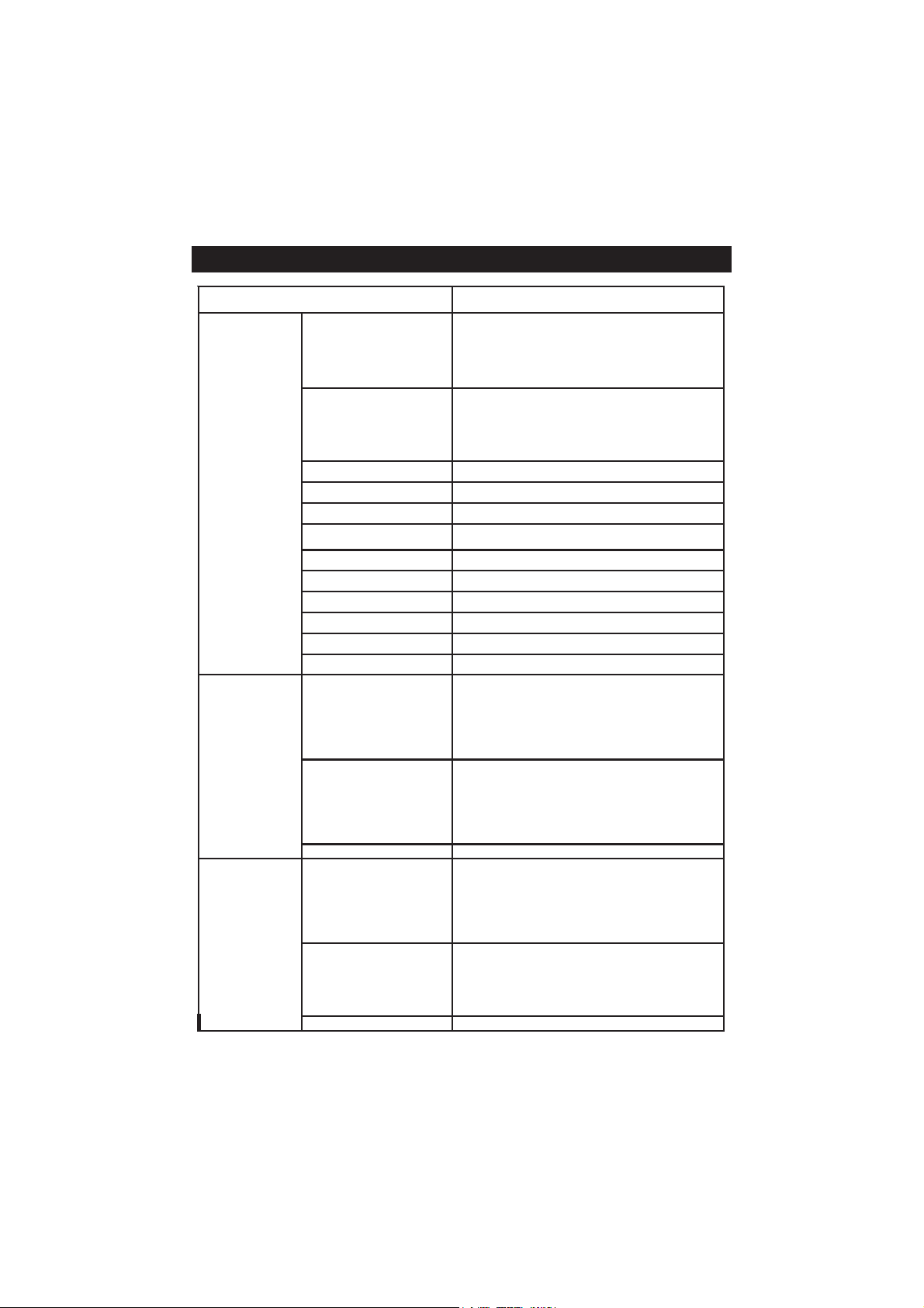
TROUBLESHOOTING GUIDETROUBLESHOOTING GUIDE
TROUBLESHOOTING GUIDE
TROUBLESHOOTING GUIDETROUBLESHOOTING GUIDE
SMOTPMYSMELBORPNOITULOS
pusetautculfgnidaeR
.)esion(nwoddna
swohsyalpsiD"-----"
.stnemerusaemgnirud
etarbilacotsliafreteM
ytluafsevigro
.sgnidaer
t'nseodtnemurtsniehT
ehterusaem
ehtmorferutarepmet
.eborp
otsliafretemehT
sevigroetarbilac
.sgnidaerytluaf
erasgninrawticilpxE
gniruddeyalpsid
.noitarbilac
.egnar
.eborp
eborpytivitcudnoC
ylreporpton
.detcennoc
fotuognidaeR
.egnar
ytivitcudnoCnekorB
eborpehT
sirosneserutarepmet
ehT/.nekorb
siecruoserutarepmet
.launamsates
sieborpehT
.degamad
degamad/ytriD
detanimatnoc,eborp
.sdradnats
.citamotua
.snoitcurtsni
yltcerroceborpehttresnI
.rotcennocehtotni
;retemehtetarbilaceR
sielpmasehtkcehC
elbarusaemehtnihtiw
.eborpehtecalpeR
teS/.eborpehtecalpeR
saecruoserutarepmeteht
.eborpehtecalpeR
deyalpsidwolloF
seodtnemurtsniehT
ehtedirrevoton
.ssecorpgnidaol
"detceteDrorrE"
.putratstapu-pop
.rorre
erawtfos/gnizilaitinI
.rorrenoitazilaitinIyb(rorreehtezilausiV
tnemurtsniehttratseR
.hctiwsrewopehtgnisu
tcatnocstsisreprorreehtfI
.rodnevruoy
"seY"gnisserp.)yek
firodnevruoytcatnoC
.sruccororrelacitirc
57
Page 58

ACCESSORIESACCESSORIES
ACCESSORIES
ACCESSORIESACCESSORIES
CONDUCTIVITY BUFFER SOLUTIONSCONDUCTIVITY BUFFER SOLUTIONS
CONDUCTIVITY BUFFER SOLUTIONS
CONDUCTIVITY BUFFER SOLUTIONSCONDUCTIVITY BUFFER SOLUTIONS
HI 70033P 84 µS/cm (µmho/cm), 20 mL sachets (25 pcs.)
HI 7033M 84 µS/cm (µmho/cm), 230 mL bottle
HI 7033L 84 µS/cm (µmho/cm), 500 mL bottle
HI 8033L 84 µS/cm (µmho/cm), 500 mL FDA approved bottle
HI 70031P 1413 µS/cm (µmho/cm), 20 mL sachets (25 pcs.)
HI 7031M 1413 µS/cm (µmho/cm), 230 mL bottle
HI 7031L 1413 µS/cm (µmho/cm), 500 mL bottle
HI 8031L 1413 µS/cm (µmho/cm), 500 mL FDA approved bottle
HI 70039P 5000 µS/cm (µmho/cm), 20 mL sachets (25 pcs.)
HI 7039M 5000 µS/cm (µmho/cm), 230 mL bottle
HI 7039L 5000 µS/cm (µmho/cm), 500 mL bottle
HI 8039L 5000 µS/cm (µmho/cm), 500 mL FDA approved bottle
HI 70030P 12880 µS/cm (µmho/cm), 20 mL sachets (25 pcs.)
HI 7030M 12880 µS/cm (µmho/cm), 230 mL bottle
HI 7030L 12880 µS/cm (µmho/cm), 500 mL bottle
HI 8030L 12880 µS/cm (µmho/cm), 500 mL FDA approved bottle
HI 7034M 80000 µS/cm (µmho/cm), 230 mL bottle
HI 7034L 80000 µS/cm (µmho/cm), 500 mL bottle
HI 8034L 80000 µS/cm (µmho/cm), 500 mL FDA approved bottle
HI 7035M 111800 µS/cm (µmho/cm), 230 mL bottle
HI 7035L 111800 µS/cm (µmho/cm), 500 mL bottle
HI 8035L 111800 µS/cm (µmho/cm), 500 mL FDA approved bottle
HI 7037L 100% NaCl sea water standard solution, 500 mL
PROBE CLEANING SOLUTIONSPROBE CLEANING SOLUTIONS
PROBE CLEANING SOLUTIONS
PROBE CLEANING SOLUTIONSPROBE CLEANING SOLUTIONS
HI 7061M General Cleaning Solution, 230 mL bottle
HI 8061M General Cleaning Solution, 230 mL FDA approved bottle
HI 7061L General Cleaning Solution, 500 mL bottle
HI 8061L General Cleaning Solution, 500 mL FDA approved bottle
OTHER ACCESSORIESOTHER ACCESSORIES
OTHER ACCESSORIES
OTHER ACCESSORIESOTHER ACCESSORIES
HI 76312 Platinum 4-ring Conductivity/TDS probe with temperature sensor and 1 m (3.3') cable
HI 7662-T Temperature probe with 1 m (3.3’) cable
HI 710005/8 12VDC voltage adapter from 115 Vac to 12 Vdc (US plug)
HI 710006/8 12VDC voltage adapter from 230 Vac to 12 Vdc (European plug)
HI 76404N Electrode holder
HI 920010 9 to 9-pin RS232 cable
HI 92000 Windows
®
compatible software
58
Page 59

RECOMMENDATIONS FOR USERS
Before using these products, make sure they are entirely suitable for the environment in which they are used.
Operation of these instruments in residential areas could cause unacceptable interferences to radio and TV equipment,
requiring the operator to follow all necessary steps to correct interferences.
The glass bulb at the end of the pH electrode is sensitive to electrostatic discharges. Avoid touching this glass bulb at all
times.
During operation, ESD wrist straps should be worn to avoid possible damage to the electrode by electrostatic discharges.
Any variation introduced by the user to the supplied equipment may degrade the instruments’ EMC performance.
To avoid electrical shock, do not use these instruments when voltages at the measurement surface exceed 24 VAC or 60
VDC.
To avoid damage or burns, do not perform any measurement in microwave ovens.
59
Page 60

SALES AND TECHNICAL SERVICE CONTACTSSALES AND TECHNICAL SERVICE CONTACTS
SALES AND TECHNICAL SERVICE CONTACTS
SALES AND TECHNICAL SERVICE CONTACTSSALES AND TECHNICAL SERVICE CONTACTS
Australia:
Tel. (03) 9769.0666 • Fax (03) 9769.0699
China:
Tel. (10) 88570068 • Fax (10) 88570060
Egypt:
Tel. & Fax (02) 2758.683
Germany:
Tel. (07851) 9129-0 • Fax (07851) 9129-99
Greece:
Tel. (210) 823.5192 • Fax (210) 884.0210
Indonesia:
Tel. (21) 4584.2941 • Fax (21) 4584.2942
Japan:
Tel. (03) 3258.9565 • Fax (03) 3258.9567
Korea:
Tel. (02) 2278.5147 • Fax (02) 2264.1729
Malaysia:
Tel. (603) 5638.9940 • Fax (603) 5638.9829
Singapore:
Tel. 6296.7118 • Fax 6291.6906
South Africa:
Tel. (011) 615.6076 • Fax (011) 615.8582
Taiwan:
Tel. 886.2.2739.3014 • Fax 886.2.2739.2983
Thailand:
Tel. 66.2619.0708 • Fax 66.2619.0061
United Kingdom:
Tel. (01525) 850.855 • Fax (01525) 853.668
USA:
Tel. (401) 765.7500 • Fax (401) 765.7575
For e-mail contacts and a complete list of Sales and Technical offices, please see
www.hannainst.com
.
60
MAN4321
10/06
 Loading...