

Page 1
HI 4113
NITRATE
COMBINATION
HI
4000-50
SENSOR HANDLE
Instruction Manual
HI 4013HI 4013
HI 4013
HI 4013HI 4013
HI 4113HI 4113
HI 4113
HI 4113HI 4113
Nitrate Ion
Selective Electrode
Half-cell
Combination
1
Page 2

HI 4013 Nitrate Half-cellHI 4013 Nitrate Half-cell
HI 4013 Nitrate Half-cell
HI 4013 Nitrate Half-cellHI 4013 Nitrate Half-cell
HI 4113 Nitrate Combination ElectrodeHI 4113 Nitrate Combination Electrode
HI 4113 Nitrate Combination Electrode
HI 4113 Nitrate Combination ElectrodeHI 4113 Nitrate Combination Electrode
I. I.
Introduction:Introduction:
I.
Introduction:
I. I.
Introduction:Introduction:
The Hanna HI 4013 and HI 4113 are ion selective electrodes designed for the measurement of nitrate ions in
aqueous solutions. They utilize a replaceable sensing module that contains an organic polymer membrane that is
sensitive to nitrate ions. The HI 4013 is a half-cell electrode
that requires a separate reference. The HI 4113 is a combination ion selective electrode.
IIII
SpecificationsSpecifications
II.
Specifications
IIII
SpecificationsSpecifications
Type: PVC membrane with or-
ganic ion exchanger
Ion measured: Nitrate (NO
Measurement range: 0.1 M to 1X 10
-
)
3
-5
M
6200 to 0.62 ppm
Interference:
Organic solvents and cationic detergents must be absent.
Ratio of interfering ion to NO
indicated below:
300 for F
-
must be less than the ratio
3
-
fluoride
100 for Cl-chloride
-
2-
3
-
2
-
4
carbonate
nitrite
iodide
perchlorate
4 for CO
2 for NO
0.01 for I
0.0045 for ClO
Operating Temperature: 0-40°C
Operating pH: 3 to 8 pH (see Section
XIII)
Dimensions: 12 mm (OD) X 120 mm
nominal insertion
(0.47” X 4.72”)
Connection: BNC
2
Page 3

III. III.
Theory of OperationTheory of Operation
III.
Theory of Operation
III. III.
Theory of OperationTheory of Operation
::
:
::
The HI 4013 and HI 4113 nitrate electrodes are potentiometric devices used for the rapid determination of free nitrate ions in water, emulsified foods and plant samples.
The electrode functions as a sensor or ionic conductor. The
HI 4013 requires a separate reference electrode to complete
its electrolytic circuit. The HI 4113 is a combination electrode with a Ag/AgCl reference electrode with gel stabilized
Cl- electrolyte in it’s inner chamber. The external reference
chamber is refillable. The PVC membrane used on the
sensor is impregnated with the organic ion exchanger. This
organic ion exchanger is considered a carrier ionophore in
that it is capable of shielding and carrying the charged
nitrate ion in it’s polar cage freely through the apolar
regions of the membrane. A charge imbalance developes
between the test solution and internal cell of the sensor.
This voltage changes in response to the sample’s ion activ-
ity. When the ionic strength of the sample is fixed, the
voltage is proportional to the concentration of nitrate ions in
solution. The sensor follows the Nernst Equation:
E = E
+ 2.3 RT/nF log A
a
ion
E = observed potential
Ea = Reference and fixed internal voltages
R = gas constant (8.314 J/K Mol)
n = Charge on ion (-1)
A
= ion activity in sample
ion
T = absolute temperature in K
F = Faraday constant (9.648 x 10⁴ C/equivalent)
3
Page 4
IV. IV.
Design elements of the HI 4013 and HI 4113Design elements of the HI 4013 and HI 4113
IV.
Design elements of the HI 4013 and HI 4113
IV. IV.
Design elements of the HI 4013 and HI 4113Design elements of the HI 4013 and HI 4113
electrodeselectrodes
electrodes
electrodeselectrodes
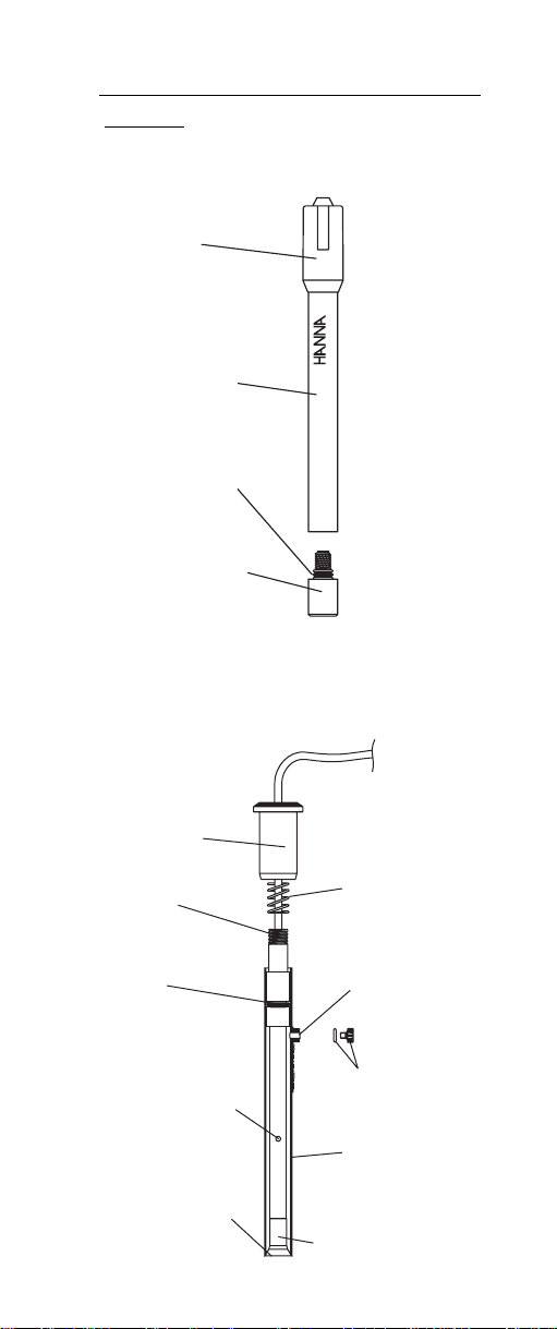
Cap
HI
4000-50
HANDLE
R
SENSO
Sensor
Handle
O-Ring
Sensing
module
Upper Cap
Upper
Threads
O-Ring
Ceramic Junction
on Inner Stem
Liquid junction
Spring
Fill Hole
O-Ring and
Plug
Outer Sleeve
Sensing Module
4
Page 5

V. V.
Equipment required:Equipment required:
V.
Equipment required:
V. V.
Equipment required:Equipment required:
• The HI 4013 requires the Hanna HI 5315 Double
junction reference electrode with HI 7078 as external
electrolyte.
• Hanna HI 4222 pH/ISE/mV meter or other suitable
ion or pH/mV meter (Note: log/linear graph paper is
useful if an ISE (ion) meter is not available).
• Hanna HI 180 magnetic stirrer or equivalent with
magnetic stirring bars (Note: Isolate beakers from stirrer motor heat by placing insulating material such as
foam or cork between them).
• Hanna HI 76404 electrode holder or equivalent.
• Plastic beakers (HI 740036P) or other suitable mea-
surement vessel.
VI. VI.
Solutions RequiredSolutions Required
VI.
Solutions Required
VI. VI.
Solutions RequiredSolutions Required
Standards for Nitrate Measurements
0.1 M sodium nitrate standard, 500 mL HI 4013-01
100 ppm nitrate standard, 500 mL HI 4013-02
1000 ppm nitrate standard, 500 mL HI 4013-03
Ionic Strength Adjuster
ISA, 500 mL HI 4013-00
Using volumetric pipettes and glassware make dilutions to
bracket the concentration of the samples. Store samples in
plastic bottles. Standards with concentrations < 10
-3
should be prepared daily.
Two mL of Hanna ISA HI 4013-00 should be added to 100
mL sample or standard.
ISISA is Interferent suppressent ISA. Dissolve 17.32g
Al2(S04)3.H20, 3.43.g Ag2SO4, 1.28g H3BO4, 2.52g
H2NSO3H in approximately 800 mL deionized water. Adjust
pH to 3 with 0.1 N NaOH. Dilute to 1 liter. Store in a dark
colored container.
50 mL of ISISA should be added to each 50 mL sample or
standard.
M
VIIVII
General GuidelinesGeneral Guidelines
VII.
General Guidelines
VIIVII
General GuidelinesGeneral Guidelines
• Ensure the o-ring is installed on modules before screw-
ing into the sensor handle or inner stem.
5
Page 6

O-Ring
• Due to shipping or storage the internal solution inside
the PVC modules may have developed an air pocket
near the membrane. Gently shaking the sensor down
(like the old style mercury thermometer) will place the
internal solution next to the membrane.
• Presoaking the Nitrate sensor in a 10
-2
M standard
without ISA for at least half-hour before calibration
will help to optimize the sensor response.
• Do not leave your sensors in standard or samples
with ISA or ISISA for long periods of time.
• Calibration standards and sample solutions should
have the same ionic strength. ISA should be added to
both samples and standards.
• Calibration standards and sample solutions should
be at same temperature.
• Thermally insulate solution vessel from magnetic stirrer.
• Calibration standards and sample solutions should
be stirred at the same rate using identical sized TFE
coated stir bars.
• Rinse electrodes with distilled or deionized water between samples and gently dab dry with lab wipe or
other soft disposable absorbent toweling. Do not rub
the sensing surface.
• Check for gas bubbles that may form near sensing
surface (due to solution temperature changes). Tap
off gently.
• Avoid large changes in temperature (thermal shock)
as it may damage the sensor.
6
Page 7

Additional HI 4113 guidelines
• Remove the protective plastic wrap that covers the
ceramic junction before assembling sensor for the first
time.
• Add reference HI 7078 fill solution to bottom of fill
hole or empty and refill fill solution daily before using.
• During measurement always operate electrode with
the fill hole open.
• During normal use, fill solution will slowly drain out
of the tapered cone junction at the lower portion of the
electrode. Excessive loss (>4 cm drop within 24 hours)
is not normal. If this occurs verify cap is tightened and
the interface between the internal cone and outer
body is free of debris.
• Add filling solution daily to maintain a good head
pressure. For optimum response, this level should be
maintained and not be allowed to drop more than 2
-3 cm (1-inch) below fill hole.
• Do not use an electrode if crystallized salts are visible
inside the electrode. Drain electrode, disassemble and
rinse internal body with deionized water. Reassemble
and refill with fresh fill solution.
• If an erratic measurement occurs, check to see if foreign matter is seen trapped near the internal cone.
Drain by depressing the electrode cap then refill with
fresh fill solution.
VIII.VIII.
Electrode PreparationElectrode Preparation
VIII.
Electrode Preparation
VIII.VIII.
Electrode PreparationElectrode Preparation
HI 4013
The Hanna HI 4013 is a 2 piece design comprised of a
sensor handle (HI 4000-50) and a sensing module (HI
4013-51). The sensor is shipped with two HI 4013-51
modules.
1. Remove sensing module from shipping vial. Do not
touch the sensing membrane with the “H” hole pattern on it.
2. Screw the module into the sensor handle finger tight.
Do not overtighten.
7
Page 8

HI
4000-50
E
L
D
N
A
H
R
O
S
N
E
S
3. Holding the assembled electrode at the cable end,
shake the sensor to ensure internal fill solution that
may have separated during shipping is in contact
with inner membrane surface.
4. Prepare HI 5315 reference electrode by filling electrolyte reservoir with HI 7078 fill solution.
5. Place sensor and reference electrodes into electrode
holder and connect cable connectors to meter.
6. Soak the Nitrate electrodes membrane in a Nitrate
containing standard (0.001M) without ISA before
calibration.
HI 4113
The Hanna HI 4113 is shipped disassembled. The sensor is
shipped with two HI 4113-51 modules.
1. Unwrap Parafilm® seal found over ceramic junction
on inner stem and discard. This is only used for shipping or long term storage.
2. Remove sensing cone from shipping vial. Do not touch
the sensing membrane with the “H” hole pattern on
it.
3. Screw the cone into the inner stem finger tight. Do not
over tighten.
8
Page 9

Remove
Water
Deionized
Parafilm
Install
sensing
module
4. Rinse inner stem with deionized water making certain
to wet o-ring found on the inner stem.
5. Reassemble electrode by gently pushing the inner
assembly into the outer body, sliding spring down
cable, and screwing cap into place.
6. Remove fill hole cover and o-ring on fill hole spout.
Using the dropper pipette provided, add a few drops
HI 7078 fill solution to the electrode. Invert the electrode to wet the o-ring and rinse the fill solution chamber.
9
Page 10

7. Holding the body of the electrode gently press upper
cap with your thumb. This permits the fill solution to
drain out of the body. Release cap and verify electrode returns to its original position. (You may need to
gently assist for this to occur).
COMBINATION
NITRATE
HI 4113
8. Tighten the electrode cap onto the body and fill electrode body until fill solution volume is just below fill
hole.
9. Position electrode in a Hanna HI 76404 electrode
holder (or equivalent) and connect BNC connector to
meter.
IX. IX.
Quick Check of Electrode SlopeQuick Check of Electrode Slope
IX.
Quick Check of Electrode Slope
IX. IX.
Quick Check of Electrode SlopeQuick Check of Electrode Slope
• Connect electrode(s) to pH/mV/ISE meter
• Place meter in mV mode.
• Place 100 mL of deionized water into a beaker with
stir bar.
• Place reference and measuring half-cell or combination electrode into prepared sample.
• Add 1 mL of a standard to beaker. Record the mV
value when stable.
• Add an additional 10 mL of standard to the
solution. Record the mV when reading has
10
Page 11

stabilized. This value should be less than the
previous value noted (more negative).
• Determine the difference between the two mV values.
An acceptable value for this slope is
56 ± 4 mV (20-25°C)
X. X.
Corrective actionCorrective action
X.
Corrective action
X. X.
Corrective actionCorrective action
• Verify module has been screwed into sensor handle or
inner stem.
• Verify Parafilm® seal has been removed from ce-
ramic junction (HI 4113 or HI 5315 reference).
• Verify fill solution has been added to reference chamber.
• Verify electrodes are connected properly to meter and
meter is powered.
• Verify dilute standards are freshly made and stored.
Remake solutions if appropriate. Store in plastic
bottles.
• If the reading is jumpy or unstable, shake sensor
down (see section VII).
• If the sensor slope just misses the suggested slope
window, soaking the sensor in a standard solution
without ISA may solve the problem.
• If the membrane is damaged, the response becomes
extremely sluggish, or the slope of the electrode has
decreased significantly, and procedures above have
not helped, the module should be replaced.
For HI 4013
1. Dry off module and sensor handle.
2. Unscrew sensing module and replace with a new one.
(HI 4013-51).
3. Soak new module in nitrate solution to condition it
before calibration.
For HI 4113
1. Drain the fill solution by depressing cap. Rinse electrode with distilled or deionized water. Drain.
11
Page 12

2. Unscrew upper cap and slide down cable toward connector.
3. Move spring and outer body down cable also.
4. Dry off inner stem and module with a soft tissue.
5. Hold inner stem and unscrew module and replace
with a new one. (HI 4113-51).
6. Reassemble electrode (see section VII), and refill with
electrolyte. Soak new membrane in nitrate solution
without ISA to condition before calibration.
XI. XI.
Direct Calibration and MeasurementDirect Calibration and Measurement
XI.
Direct Calibration and Measurement
XI. XI.
Direct Calibration and MeasurementDirect Calibration and Measurement
This method is a simple procedure for measuring many
samples. A direct reading ISE meter (HI 4222 or equivalent) determines concentration of the unknown by a direct
reading after calibrating the meter with the standards. Add
HI 4013-00 to adjust ionic strength at a dose of 2 mL of per
100 mL sample or standard. ISISA* may also be used at a
dose of 50 mL for 50 mL of sample or standard. The meter
is calibrated using freshly made standards that are in the
measurement range of the unknowns. Unknowns are read
directly. In the region where the electrode calibration becomes less linear, more calibration points are needed, and
calibration will need to be repeated more frequently.
A pH/ mV meter in mV mode and semi log graph paper
may also be used. Two or more freshly prepared standards
that are in the measurement range of the unknowns are
measured in mV mode on the meter.
These values are plotted on the semi-log paper and the
points are connected to form a straight-line curve. When
samples are measured, their mV values are converted to
concentration by following the mV to the concentration axis
on the semi-log plot.
*Note: ISISA is the recommended ISA used for procedure
4500-NO3-D. published in Standard Methods for the Examination of Water and Wastewater.
12
Page 13

Procedure:
Follow sections VIII and IX to prepare electrodes for measurement.
1) Follow section VI to prepare standards/ solution. Standards should bracket and fall within the range of
interest. Standards and solutions should be at the
same temperature.
• 2 mL of HI 4013-00 is added to 100 mL of both
samples and standards. OR
• 50 mL of ISISA are added to 50 mL both samples
or standards.
Add stir bar and mix before taking measurements.
2) Follow section VII; General Guidelines to optimize test
set-up.
3) During calibration it is best to start with lower concentration samples first. Wait for a stable reading before
reading/ recording values. Permit longer equilibration times at these levels (3 or 4 minutes).
To prevent carry over and contamination of samples, rinse
sensors with deionized water and remove moisture with
absorbant tissue between samples.
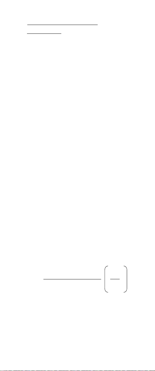
Typical HI 4013 and HI 4113 Linearity
0
50
100
150
mV
200
250
300
0123 4567
-L og of Molar Concentration
13
Page 14
XII. XII.
Other Measurement TOther Measurement T
XII.
Other Measurement T
XII. XII.
Other Measurement TOther Measurement T
Known additionKnown addition
Known addition
Known additionKnown addition
echniquesechniques
echniques
echniquesechniques
An unknown concentration can be determined by adding a
known volume and concentration of NO
-
standard to the
3
sample. mV values are noted before and after the addition
of standard (∆E). An ideal sensor slope can be used in the
equation but actual determined slopes at the temperature
of measurement should be used if known (S). This method
is preprogrammed in the Hanna HI 4222 pH/ISE/mV meter,
which simplifies the method greatly.
Example:
Nitrate ion determination with known addition.
1. A 50 mL sample of unknown (V
) is placed in a
SAMPLE
clean plastic beaker with an electrode (s). Add 50 mL
of ISISA* to sample. Mix. mV 1 is recorded.
2. 5 mL (V
STANDARD
) of 10
-1
M (C
) standard is added
STANDARD
to the beaker and the mV value decreases. (Note: for
other concentration samples, add a known volume
and concentration of standard to produce approximately 30 mV change).
The unknown Nitrate concentration in the original
sample (C
) can then be determined by using the
SAMPLE
equation that follows.
3. The procedure can be repeated with second standard
addition to verify slope and operation of the method.
C
C
=
sample
(V
T
(V
sample+Vstandard+VISA
(V
sample+VISA
standardVstandard
∆E/S
)10
- (VS’)
)= V
)= V
S’
V
V
S’
sample
T
*Note: ISISA is Interferent suppressent ISA see Section IV.
14
Page 15

XIIIXIII
pH and Interferents pH and Interferents
XIII.
pH and Interferents
XIIIXIII
pH and Interferents pH and Interferents
HI 4013/ HI4113 Nitrate electrodes can operate over a pH
range of 3 to 8 but better results are found if pH is kept
constant throughout calibration and test. Sulfuric acid or
NaOH can be used for pH adjustment or use ISISA to surpress
interferences and buffer pH. Limiting the length of time of
exposure to samples containing interferences will prolong
useful life of your electrode. If sensor has been exposed to
ions above recommended levels, soaking in pure nitrate
solutions without ISA will aid recovery of function.
XIV.XIV.
Storage and Care of the HI 4013 andStorage and Care of the HI 4013 and
XIV.
Storage and Care of the HI 4013 and
XIV.XIV.
Storage and Care of the HI 4013 andStorage and Care of the HI 4013 and
HI 4113 electrodesHI 4113 electrodes
HI 4113 electrodes
HI 4113 electrodesHI 4113 electrodes
The HI 4013 sensor can be stored in standards that do not
contain ISA for short time periods. For long term storage,
unscrew sensing module from sensor handle and store dry
in the shipping vial.
The model HI 4113 combination electrode can be left in
dilute standards that do not contain ISA for short time
periods. If the electrode will be used frequently and needs
to be ready for use, take measures to prevent evaporation of
fill solution. Top off fill solution, replace o-ring, fill hole
cover on the fill hole opening, and place sensor in dilute
nitrate solution that does not contain ISA. Store electrode
upright. Prior to use, drain electolyte chamber and refill
with fresh HI 7078 fill solution.
For long term storage, the electrode should be drained,
disassembled and washed of salts with deionized water.
Wrap the ceramic junction in Parafilm® or other sealing
wrap. Unscrew the module and store dry in the shipping
vial. Refrigeration of module will extend its life. Store disassembled electrode in storage box provided with electrode.
XV. XV.
Conversion tablesConversion tables
XV.
Conversion tables
XV. XV.
Conversion tablesConversion tables
--
-
--
For NOFor NO
For NO
For NOFor NO
33
3
33
Moles/L (M) NO
-
to ppm NO
3
Multiply by Multiply by
Multiply by
Multiply by Multiply by
-
(mg/L) 620 00
3
ppm (mg/L) to M (moles/L) 1.61 X 10
15
-5
Page 16

MAN4113 07/06R1
WARRANTY WARRANTY
WARRANTY
WARRANTY WARRANTY
Hanna Instruments Ion Selective Electrodes are warranted
to be free of defects in material and workmanship for 6
months from date of purchase when used for their intended
purpose and maintained according to instructions. If they
fail to work when first used contact your dealer immediately.
Damage due to accidents, misuse, misapplication, tampering
or lack of prescribed maintenance is not covered.
Hanna Instruments reserves the right to modify the design,
construction or appearance of its products without advance
notice.
16
 Loading...