

Page 1
HI 4110
FLUORIDE
COMBINATION
HI 4010
FLUORIDE
Instruction Manual
HI 4010HI 4010
HI 4010
HI 4010HI 4010
HI 4110HI 4110
HI 4110
HI 4110HI 4110
Fluoride Ion
Selective Electrode
Half-cell
Combination
1
Page 2

HI 4010 Fluoride Half-cellHI 4010 Fluoride Half-cell
HI 4010 Fluoride Half-cell
HI 4010 Fluoride Half-cellHI 4010 Fluoride Half-cell
HI 4110 Fluoride Combination ElectrodeHI 4110 Fluoride Combination Electrode
HI 4110 Fluoride Combination Electrode
HI 4110 Fluoride Combination ElectrodeHI 4110 Fluoride Combination Electrode
I. I.
Introduction:Introduction:
I.
Introduction:
I. I.
Introduction:Introduction:
The Hanna HI 4010 and HI 4110 are ion selective electrodes designed for the measurement of fluoride ions in
aqueous solutions. The HI 4010 is a solid state half-cell
sensor that requires a separate reference. The HI 4110 is a
combination ion selective electrode.
IIII
SpecificationsSpecifications
II.
Specifications
IIII
SpecificationsSpecifications
Type: Solid State electrode with
a Lanthanum Fluoride
crystal membrane.
Ion(s) measured: Fluoride (F-)
Measurement range: Saturated to 1X 10⁻⁶M
Saturated to 0.02 ppm
Interfering ions: OH
Note:
Several other ions (Al3+, Fe3+) that complex with the
measured species will reduce the ion concentrations
measured directly. TISAB reagent should be used in most of
these cases. H+ ion also forms HF species below pH 5.
Increase pH in these cases above 5 for a total fluoride
measurement.
Operating Temperature: 0-80°C
-
Operating pH: 5 to 8 pH
Dimensions: 12 mm (OD) X 120 mm
nominal insertion
(0.47” X 4.72”)
Connection: BNC
2
Page 3

III. III.
Theory of OperationTheory of Operation
III.
Theory of Operation
III. III.
Theory of OperationTheory of Operation
::
:
::
The HI 4010 or HI 4110 fluoride electrodes are potentiometric devices used for the rapid determination of free fluoride ions in water, soft drinks, wine, emulsified foods, and
plating and pickling acids. The electrode functions as a
sensor or ionic conductor. The HI 4010 requires a separate
reference electrode to complete its electrolytic circuit. The
HI 4110 has a reference electrode incorporated in its design. The lanthanum fluoride crystalline pellet is practically insoluble in the test solutions being measured and
produces a potential change due to changes in the sample’s
ion activity. When the ionic strength of the sample is fixed,
the voltage is proportional to the concentration of fluoride
ions in solution and the electrode follows the Nernst equation.
E= E
+ 2.3 RT/nF log A
a
ion
E= observed potential
Ea= Reference and fixed internal voltages
R= gas constant (8.314 J/K Mol)
n= Charge on ion (1-)
A
=ion activity in sample
ion
T= absolute temperature in K
F= Faraday constant (9.648 x 10
3
4
C/equivalent)
Page 4
IV. IV.
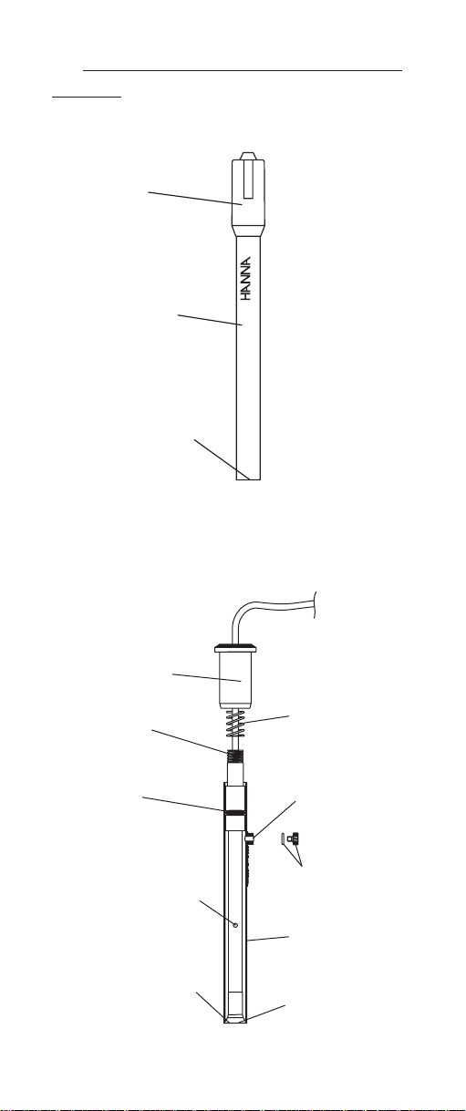
Design elements of the HI 4010 and HI 4110Design elements of the HI 4010 and HI 4110
IV.
Design elements of the HI 4010 and HI 4110
IV. IV.
Design elements of the HI 4010 and HI 4110Design elements of the HI 4010 and HI 4110
electrodeselectrodes
electrodes
electrodeselectrodes
Cap
HI 4010
RIDE
Sensor
FLUO
Handle
Sensing
Crystal
Upper Cap
Upper
Threads
O-Ring
Ceramic Junction
on Inner Stem
Liquid junction
Spring
Fill Hole
O-Ring and
Plug
Outer Sleeve
Sensing
Crystal
4
Page 5

V. V.
Equipment requiredEquipment required
V.
Equipment required:
V. V.
Equipment requiredEquipment required
• Hanna HI 5315 double junction reference electrode
with HI 7075 fill solution for measurements with
HI 4010.
• Hanna HI 4222 pH/ISE/mV meter or other suitable
ion or pH/mV meter. (Note: log/linear graph paper is
useful if an ISE (ion) meter is not available.
• Hanna HI 180 magnetic stirrer or equivalent with
stirring bars (HI 731320). (Note: isolate beakers from
stirrer motor heat by placing insulating material such
as foam or cork between them).
• Hanna HI 76404 electrode holder or equivalent.
• Plastic beakers (HI 740036P) or other suitable mea-
surement vessel.
VI. VI.
Solutions RequiredSolutions Required
VI.
Solutions Required
VI. VI.
Solutions RequiredSolutions Required
Standard for Fluoride Measurements
Select appropriate Hanna Instruments standard and ISA
from the list below: Part number
0.1 M Sodium Fluoride, 500 mL HI 4010-01
100 ppm, 500 mL HI 4010-02
1000 ppm, 500 mL HI 4010-03
10 ppm with TISAB II, 500 mL HI 4010-10
1 ppm with TISAB II, 500 mL HI 4010-11
2 ppm with TISAB II, 500 mL HI 4010-12
*
*
*
ISA
TISAB II, 500 mL HI 4010-00
TISAB II, 1 gallon HI 4010-05
TISAB III , 500 mL HI 4010-06
KIT: HI 4010-30
Contains four 500 mL bottles of:
TISAB II HI 4010-00
10 ppm with TISAB II HI 4010-10
1 ppm with TISAB II HI 4010-11
Standards that are asterisked contain TIASB II and are
*
ready to use withour further additions.
5
*
*
Page 6

Using volumetric pipettes and glassware make dilutions to
bracket the concentration of the samples. Standards with
concentrations < 10
daily. Standards that are asterisked contain TISAB II and
should be used directly with no additional TISAB II added.
Samples used with these standards should have TISAB II
added. To 50 parts standard or sample add 50 parts TISAB
II (HI 4010-00, HI 4010-05) or to 50 parts standard or
sample add 5 parts of TISAB III concentrate (HI 4010-06).
Note: TISAB is formulated for water sample analysis to
provide samples and standards a constant ionic strength
and pH background that stabilizes the solutions activity
coefficient and permits concentration to be measured directly. It preferentially complexes various metal ions (i.e.
Aluminum; Al3+, Iron; Fe3+) that also complex with fluoride thus permitting a total fluoride measurement. Contact
Hanna Instruments for guidelines with other applications.
VIIVII
General GuidelinesGeneral Guidelines
VII.
General Guidelines
VIIVII
General GuidelinesGeneral Guidelines
• Calibration standards and sample solutions should
have the same ionic strength. Use the same TISAB (II
or III) for both samples and standards. Always prepare samples and standards with the same ISA to
volume ratio.
• Calibration standards and sample solutions should
be at same temperature.
• Thermally insulate beaker with standard or sample
from magnetic stirrer.
• Calibration standards and sample solutions should
be stirred at the same rate using identical sized TFE
coated stir bars.
• Rinse electrodes with distilled or deionized water between samples and gently dab dry with lab wipe or
other soft disposable absorbent toweling. Do not rub
crystal.
• Presoaking fluoride sensor in a standard near sample
concentrations will activate crystal and optimize response.
-4
M (1.9 ppm) should be prepared
*
6
Page 7

• A slightly scratched crystal may benefit from a treatment with a fluoride containing toothpaste (without
baking soda). Lightly wipe the sensor tip with the
mild abrasive. Rinse well with deionized and soak in
a fluoride standard near measurement value.
• Avoid large changes in temperature (thermal shock)
as it may damage the sensor.
HI 4010
• Remove protective cover from sensor tip.
HI 4110
• Remove the protective plastic wrap that covers the
ceramic junction before assembling sensor for the first
time.
• Ensure o-ring is installed on sensing module before
screwing into the inner stem.
O-Ring
• Add reference HI 7075 fill solution daily to maintain
a good head pressure. For optimum response, this
level should be maintained and not be allowed to
drop more than 2-3 cm (1-inch) below fill hole.
• During measurement always operate electrode with
the fill hole open.
• During normal use, fill solution will slowly drain out
of the tapered cone junction at the lower portion of the
electrode. Excessive loss (>4 cm drop within 24 hours)
is not normal. If this occurs verify cap is tightened and
the interface between the internal cone and outer
body is free of debris.
• If an erratic measurement occurs, check to see if foreign matter is seen trapped near the internal cone.
Drain and refill with fresh fill solution.
7
Page 8

VIII. VIII.
Electrode PreparationElectrode Preparation
VIII.
Electrode Preparation
VIII. VIII.
Electrode PreparationElectrode Preparation
HI 4010
1. Remove protective cover from HI 4010 sensor tip.
2. Due to shipping or storage the internal solution inside
the electrode may have developed an air pocket near
the membrane. Gently shaking the sensor down (like
the old style mercury thermometer) will place the internal solution next to the membrane. Note: when the
sensor is inverted an air pocket will be seen which is
normal.
3. Prepare HI 5315 reference electrode by filling outer
electrolyte reservoir with HI 7075.
4. Place sensor and reference electrodes into electrode
holder and connect cable connectors to meter.
HI 4110
1. Unwrap plastic film seal found over ceramic junction
on inner stem and discard. This is only used for shipping and long term storage.
2. Open the glass vial that contains the fluoride module
(HI 4110-51) and remove from container.
3. Ensure the o-ring is installed on module before screwing into inner stem. Do not over tighten.
4. Due to shipping or storage the internal solution inside
the module may have developed an air pocket near
the membrane. Gently shaking the sensor down (like
the old style mercury thermometer) will place the internal solution next to the membrane. Note: When
inverted, an air pocket will be visible inside the sensor
which is normal.
5. Rinse inner stem with deionized water making certain
to wet the o-ring found on the inner stem.
8
Page 9

Remove
Water
Deionized
Parafilm
Install
sensing
module
6. Reassemble electrode by gently pushing the inner
assembly into the outer body, sliding spring down
cable, and screwing cap into place. DO NOT TOUCH
OR PUT PRESSURE ON LANTHANUM CRYSTAL.
7. Remove fill hole cover and o-ring on fill hole spout.
8. Using the dropper pipette provided, add a few drops
of HI 7075 fill solution to the electrode, wetting the oring and rinsing out the fill solution chamber.
9
Page 10

9. Holding the body of the electrode gently press upper
cap with your thumb. This permits the fill solution to
drain out of the body. Release cap and verify electrode returns to its original position (you may need to
gently assist for this to occur).
TION
BINA
COM
FLUORIDE
HI 4110
10. Tighten the electrode cap onto the body and fill electrode body until fill solution volume is just below fill
hole.
11. Position electrode in a Hanna HI 76404 electrode
holder (or equivalent) and connect plug to meter.
IX. IX.
Quick Check of Electrode SlopeQuick Check of Electrode Slope
IX.
Quick Check of Electrode Slope
IX. IX.
Quick Check of Electrode SlopeQuick Check of Electrode Slope
• Connect sensors to pH/mV/ISE meter.
• Place meter in mV mode.
• Place 100 mL of deionized water into a beaker with
stir bar.
• Place the electrodes into prepared sample.
• Add 1 mL of a standard (0.1 M or 1000 ppm stan-
dard) to beaker. Record the mV value when stable.
• Add an additional 10 mL of standard to the solution.
Record the mV when reading has
10
Page 11

stabilized. This value should be less than the previous noted (more negative).
• Determine the difference between the two-mV values.
An acceptable value for this slope is -56 ± 4 mV.
X. X.
Corrective actionCorrective action
X.
Corrective action
X. X.
Corrective actionCorrective action
• Verify protective cap has been removed (HI 4010).
• Verify plastic film has been removed from inner stem
(HI 4110 or HI 5315 electrode).
• Verify electrodes are connected properly to meter and
meter is powered. For HI 4110 verify sensor is screwed
into the inner stem.
• Verify dilute standards are freshly made and stored.
Remake solutions if appropriate.
• If the sensor slope just misses the suggested slope
window, soaking the sensor in a standard may solve
the problem. (Choose 10
-2
M fluoride or 1000 ppm
standard).
• A scratched sensing surface can be polished with fluoride toothpaste (without baking soda). Use a small
drop of the paste and a soft wipe. Using a circular
motion, and gentle pressure, rub the surface of the
electrode with this micro abrasive material. Rinse
with water. Check to see if small scratches have been
eliminated. Rinse in deionized water and blot dry.
Soak in a fluoride standard for 1 hour. Repeat section
IX.
• If the reading is jumpy or unstable, shake sensor
down (see section VIII).
• If the membrane is damaged, the response becomes
extremely sluggish, or the slope of the electrode has
decreased significantly, and procedures above have
not helped, the sensor (or module) should be replaced.
11
Page 12

For HI 4110 module replacement
1. Drain the fill solution by pressing the upper cap.
Rinse electrode with distilled or deionized water. Drain.
2. Unscrew upper cap and slide down cable toward connector.
3. Move spring and outer body down cable also.
4. Dry off inner stem and module with a soft tissue.
5. Hold inner stem and unscrew module and replace
with a new one. (HI 4110-51).
6. Reassemble electrode (see section VIII), and refill
with electrolyte. Soak new membrane in fluoride
solution to condition before calibration.
XI. XI.
Direct Calibration and MeasurementDirect Calibration and Measurement
XI.
Direct Calibration and Measurement
XI. XI.
Direct Calibration and MeasurementDirect Calibration and Measurement
This method is a simple procedure for measuring many
samples. A direct reading ISE meter (HI 4212 or equivalent) determines concentration of the unknown by a direct
reading after calibrating the meter with the standards. The
meter is calibrated with two or more freshly made standards that are in the linear measurement range of the
unknowns. More calibration standards are required in nonlinear regions. Unknowns are read directly.
A pH/mV meter in mV mode with semi log graph paper
may also be used. Two or more freshly prepared standards
that are in the measurement range of the unknowns are
measured in mV mode on the meter.
These values are plotted on the semi-log paper and the
points are connected to form a straight-line curve. When
samples are measured, their mV values are converted to
concentration by following the mV to the concentration axis
on the semi-log plot.
At very low levels of fluoride, special precautions must be
employed for reproducible measurements. Water used for
standards must be fluoride free and sensors and glassware
must be rinsed repeatedly with this water to prevent carry
over. In the region where the electrode calibration becomes
curved, many more calibration points are needed, and
calibration will need to be repeated more frequently.
12
Page 13

If no fluoride complexing species are in the sample, TISAB
V
needn’t be added at the same proportions. Add 1 parts
TISAB to 100 parts sample or standard. Ionic strength will
be fixed at approximately 0.02M. Attention: Always prepare samples and standards with the same ISA to volume
ratio.
1) Follow sections VIII and IX to prepare sensors for
measurement.
2) Follow section VI to prepare standards/solution. Standards should bracket the sample concentration. Standards and solutions should be at the same temperature.
1 part of TISAB is added to 100 parts of both samples
and standards. Add stir bar and mix before taking
measurements.
3) Follow section VII; General Guidelines to optimize test
set-up.
4) During calibration it is best to start with lower concentration samples first. Wait for a stable measurement
before recording values. Longer equilibrations are required at lower concentrations (4-5 minutes).
5) To prevent carry over and contamination of samples,
rinse sensors with deionized water and dab dry between samples.
Typical Linearity for HI 4010 and HI 4110 Sensors
-150.00
-100.00
-50.00
0.00
m
50.00
100.00
150.00
200.00
250.00
0.00 1.00 2.00 3.00 4.00 5.00 6.00 7.00 8.00
-Log of Concentration
13
Page 14

XII. XII.
Other Measurement TOther Measurement T
XII.
Other Measurement T
XII. XII.
Other Measurement TOther Measurement T
echniquesechniques
echniques
echniquesechniques
Known addition (for F-)
An unknown concentration can be determined by adding a
known amount (volume and concentration) of measured
ion to a known volume of the sample. This technique is
useful for very low F- concentration samples. It can use an
ideal sensor slope, but actual determined slopes at the
temperature of measurement should be used if known.
This method is preprogrammed in the Hanna HI 4222 pH/
ISE/mV meter, which simplifies the method greatly.
Example: Fluoride ion determination with known addition.
1. A 50 mL sample of unknown (Vsample) is placed in
a clean plastic beaker with cleaned electrodes. The
mV 1 is recorded. If fluoride metal complexes are
present add 50 mL TISAB II (V
). Mix well then
TISAB
take mV value.
2. 5 mL (Vstd) of 10-3M (Cstd) standard is added to the
beaker and the mV value decreases. The unknown
fluoride concentration in the original sample
(Csample) can then be determined by the following
equation.
C
=
sample
(V
sample+Vstandard+VISA
(V
C
standardVstandard
(V
)10
T
sample+VISA
∆E/S
)= V
- (VS’)
)= V
S’
V
S’
V
sample
T
3. The procedure can be repeated with a second stan-
dard addition to verify slope and operation of the
method.
Titration
Titration can be used to measure an ion that doesn’t
have an ion selective sensor. An example of this is the use
of the Hanna HI 4110 or HI 4010 fluoride electrode for
aluminum (Al3+) determination. Because the
stoichiometry between the two species is variable fixing
the pH and titrating to a fixed endpoint is advised.
14
Page 15

Five mL acetate buffer (3.7 M HOAC/0.76M 0AC- in
composition) is added to 100 mL of sample. A standard
aluminum solution is first titrated with a fluoride solution
to determine the endpoint value. Measurements may be
automated by use of the Hanna Titrator HI 901 or titrated
manually.
pHpH
pH
pHpH
XIII.XIII.
XIII.
XIII.XIII.
The HI 4110 and HI 4010 sensors measure fluoride ions
between 5 and 8 pH.
XIV. XIV.
Storage and Care of the HI 4010 andStorage and Care of the HI 4010 and
XIV.
Storage and Care of the HI 4010 and
XIV. XIV.
Storage and Care of the HI 4010 andStorage and Care of the HI 4010 and
HI 4110 sensorsHI 4110 sensors
HI 4110 sensors
HI 4110 sensorsHI 4110 sensors
The HI 4010 sensor can be stored in standards near
measured values for short periods of time and should be
stored dry with the protective cap on when not in use for
long periods of time. The model HI 4110 combination
electrode can be left in standards that were used for
calibration for short time periods. If the electrode will be
used frequently and needs to be ready for use, take measures
to prevent evaporation of fill solution. Top off fill solution,
and replace o-ring and plug on fill hole opening. Place
sensor tip in a dilute fluoride standard, positioned upright.
Prior to use, drain electolyte chamber and refill with fresh
fill solution.
For long term storage, the electrode should be drained,
disassembled and washed of salts with deionized water.
Wrap the ceramic junction in Parafilm® or other sealing
wrap. Unscrew the fluoride module and store dry in the
shipping vial. Store disassembled electrode in storage box
provided with electrode.
Conversion tablesConversion tables
Conversion tables
Conversion tablesConversion tables
XV.XV.
XV.
XV.XV.
--
-
--
For FFor F
For F
For FFor F
Multiply byMultiply by
Multiply by
Multiply byMultiply by
Moles/Liter (M) to ppm (mg/L) 1.900 x 10
ppm (mg/L) to M (Moles/Liter) 5.263 x 10
15
4
-5
Page 16

MAN4110 10/02/R3
WARRANTY WARRANTY
WARRANTY
WARRANTY WARRANTY
Hanna Instruments Ion Selective Electrodes are warranted
to be free of defects in material and workmanship for 6
months from date of purchase when used for their intended
purpose and maintained according to instructions. If they
fail to work when first used contact your dealer immediately.
Damage due to accidents, misuse, misapplication, tampering
or lack of prescribed maintenance is not covered.
Hanna Instruments reserves the right to modify the design,
construction or appearance of its products without advance
notice.
16
 Loading...